Seized hydraulic fittings need a controlled assessment before you apply more force: isolate the equipment, release stored energy, identify the connection, and decide whether removal can proceed without damaging the port. A larger wrench cannot tell you whether corrosion, crossed threads, damaged sealing surfaces, or mechanical loading caused the problem. The practical goal is to protect the equipment connection and install a verified replacement, rather than preserve every old component. This guide explains how to evaluate a stuck fitting, recognize the limits of removal attempts, and collect the information needed for a reliable hydraulic hose assembly replacement.
Make the Hydraulic System Safe Before Touching the Connection
A fitting that will not turn is a maintenance problem; a fitting retaining hydraulic pressure is an immediate hazard. Establish the equipment’s safe maintenance condition before cleaning, measuring, or attempting disassembly.
Control Pressure, Stored Energy, and Contamination
Stopping the pump does not establish that every circuit is depressurized, particularly where accumulators, suspended loads, or isolated sections can retain energy. Follow the equipment manufacturer’s isolation and pressure-release procedures, secure loads as required, and verify the safe condition at the specified points.
Prepare the work area before opening the circuit so that fluid and exposed connections remain controlled throughout the repair. Clean accessible surfaces, provide suitable collection equipment, and have correctly identified protective caps or plugs ready rather than leaving open ports exposed while searching for parts. Keep these preliminary checks together:
- Confirm isolation, stored-energy control, and the manufacturer’s required verification procedure.
- Identify the hydraulic fluid, operating temperature, and any special handling restrictions.
- Establish how disconnected lines and ports will be protected from contamination.
- Never use your hand to locate a pinhole leak or loosen a connection as an improvised pressure-release method; follow the applicable safety instructions.
Identify What Is Actually Stuck
Determine which joint must separate before selecting a tool. A hose swivel nut, an adapter threaded into a manifold, and a broken threaded stub present different removal problems.
Separate the Hose Connection From the Equipment Port
Trace the connection from the hose to the equipment and distinguish the hose fitting, any intermediate adapter, and the port body. Record which component moves and which remains stationary, because turning the wrong hex can loosen an adjacent joint, rotate the hose, or transfer load into the manifold. Where the connection design provides suitable holding flats, use the specified backup arrangement to control the intended joint rather than allowing the assembly to react against unsupported tubing or hose.
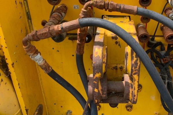
Inspect accessible areas for corrosion, damaged wrench flats, misalignment, and evidence of previous repair attempts, but treat these observations as clues rather than a diagnosis. Rust outside a connection does not establish the condition of the engaged threads, and a rounded nut may prevent tool engagement even when the threads themselves are serviceable. Photograph the complete arrangement before disturbing it so that adapter position, elbow orientation, and surrounding clearance can be checked during replacement.
| Observed condition | What to establish next | Why it changes the repair |
| Swivel nut will not turn | Which body requires backup support and whether the hose is loaded | Helps prevent twisting the hose or disturbing another joint |
| Adapter is stuck in a manifold | Port connection, sealing arrangement, and accessible holding features | The equipment port may be more costly to replace than the adapter |
| Wrench flats are rounded | Whether an approved tool can still engage the component | Additional force through a poor grip can remove remaining purchase |
| Fitting has broken at the port | Remaining geometry and condition of the surrounding body | Extraction requires a separate assessment |
| Threads began binding during installation | Correct thread, alignment, and possible cross-threading | Further tightening may extend existing damage |
Choose Removal Methods by Condition, Not by Force
Use removal methods that fit the connection and the equipment manufacturer’s instructions. There is no universal sequence of penetrant, hammering, heating, and tightening that guarantees undamaged hydraulic threads.
Know the Limits of Penetrants, Movement, and Heat
For accessible external corrosion, a compatible penetrating product may be considered where its instructions and the equipment procedures permit use. Keep it away from exposed hydraulic passages and verify compatibility with nearby seals, coatings, and materials; do not assume diesel fuel, kerosene, and commercial penetrants are interchangeable. Follow the selected product’s instructions rather than publishing a fixed waiting time as a guarantee, since penetration depends on access to the affected interface and the actual condition of the joint.
Use a tool that fully engages the intended wrenching feature, maintain alignment, and avoid increasing leverage simply because the fitting has not moved. Small controlled movement may be permitted for some connections, but “tighten first, then loosen” should not become a default instruction for tapered threads, suspected cross-threading, or damaged parts.
Heating requires a separate assessment of the assembly, including the fluid, seals, hose, nearby components, and any chemical products already applied. Do not transfer a temperature from a threadlocker removal sheet to an unidentified hydraulic connection, or assume that heating the male fitting produces the desired clearance. Stop when tool engagement deteriorates, the surrounding body moves unexpectedly, or the approved procedure no longer provides a defensible next step; preserving a damaged fitting is not a reason to risk the equipment port.
Confirm the Replacement Thread and Sealing Interface
A replacement fitting must match both the mechanical connection and its sealing arrangement. Similar appearance, matching wrench size, or a few turns of thread engagement cannot establish interchangeability.
Measure the Connection and Locate the Seal
Record whether each end is male or female, whether the thread is straight or tapered, and the measured thread diameter and pitch or threads per inch. Then identify the connection standard, seat geometry, sealing face, and any O-ring or sealing washer arrangement using an appropriate identification reference. JIC, SAE 45-degree flare, NPT/NPTF, BSPP/BSPT, ORFS, ORB, metric, DIN, and JIS descriptions should lead to a specific verified configuration, rather than being treated as broad groups of interchangeable parts.
The thread retains or positions a connection, but the sealing interface depends on the design; identifying one does not complete identification of the other. Parker’s connection literature distinguishes flare, face-seal, and straight-thread port arrangements, illustrating why thread dimensions alone are insufficient for selecting a replacement. Use photographs for preliminary screening, then confirm dimensions and sealing details against the relevant product data, especially when corrosion or damage has obscured the original features.
Before ordering, preserve the evidence needed to check the proposed replacement against the original installation:
- Record the existing part number and photograph the complete fitting, thread, and sealing face.
- Measure thread diameter and pitch, then confirm taper, seat angle, and sealing method.
- Note elbow angle, overall dimensions, orientation, and tool-access restrictions.
- Specify the equipment application, hydraulic fluid, temperature, and required working pressure.
Verify the Hose Side When Replacing a Crimped Fitting
Matching the equipment connection does not establish that a fitting can be attached to the existing hose. The hose end requires its own compatibility and assembly verification.
One-Piece Construction Does Not Replace Crimp Data
A one-piece hydraulic hose fitting combines the fitting body or stem and ferrule into a preassembled or retained unit, with the exact construction depending on the product series. This arrangement can reduce separate ferrule selection and picking steps, but it does not automatically establish hose compatibility, correct crimping, or suitability as a replacement. It also should not be confused with reusable or field-attachable designs, which have their own specified components and assembly procedures.
For a replacement hose assembly, confirm the hose manufacturer and series, construction, inside diameter or dash size, fitting stem design, and ferrule design. Obtain the validated assembly instructions covering skive or no-skive preparation, insertion depth, die selection, crimp diameter, and the applicable crimping equipment; equal dash sizes do not supply this missing information.
Do not treat the lowest component rating as automatic approval of an otherwise unverified assembly: compatibility must be established first, and the permissible service envelope cannot exceed the limiting approved component or applicable assembly rating. Review pressure impulse, temperature, fluid compatibility, corrosion exposure, vibration, mechanical loading, routing, and installation conditions against the selected product documentation. Burst pressure is not allowable working pressure, and a visually similar fitting or a convenient crimp setting cannot substitute for validated application and assembly data.
Inspect the Port and Plan the Return to Service
Successful removal only creates an opportunity to inspect the connection. Reassembly should proceed after the port, sealing surfaces, and replacement assembly have been assessed against the applicable acceptance criteria.
Complete the Repair Record Before Reassembly
Inspect the accessible internal threads, port entry, sealing face, and surrounding body for damage before fitting a replacement, and obtain further assessment where the condition is uncertain. Do not present running a tap through the port as routine nondestructive cleaning: thread restoration can remove material and introduce chips, while damaged geometry may remain unsuitable for service. Follow the equipment manufacturer’s repair limits, cleaning requirements, assembly instructions, and specified return-to-service checks rather than assuming that a replacement turning into the hole proves the repair acceptable.
Record the confirmed part identification and assembly information so the next repair begins with usable evidence rather than another visual guess. Include the reason for replacement and any change to routing or orientation, then retain the approved crimp reference and inspection record where relevant. Before releasing the repair, complete a neutral technical confirmation checklist:
- Connection: verified thread standard, size, sealing interface, and installation dimensions.
- Hose assembly: identified hose series, fitting series, preparation method, and validated crimp specification.
- Application: approved pressure, temperature, fluid, routing, and environmental suitability.
- Equipment condition: assessed port and sealing surfaces, controlled contamination, and completed manufacturer-required checks.
- Replacement record: part numbers, photographs, assembly details, and any outstanding restrictions.
Conclusion
The right response to seized hydraulic fittings is a controlled repair decision, not an escalating contest with the wrench. Establish the safe condition, identify the joint, and stop when the approved removal approach no longer protects the equipment. Once the fitting is out, check the port before treating the job as a straightforward replacement. Match the thread and sealing interface, then verify hose compatibility and crimp requirements if a new assembly is needed. Correct matching matters more than visual similarity or the lowest unit price. Prepare the original part reference, connection measurements, sealing-face photographs, hose details, and operating conditions so the replacement can be checked against documented requirements before the equipment returns to service.
Frequently Asked Questions
Can the old crimped fitting be installed on a new hose?
Do not assume that a removed crimp fitting is reusable. Check the fitting manufacturer’s explicit reuse instructions, and distinguish permanent crimp products from fittings specifically designed for field attachment or reuse. A matching thread end does not change the hose attachment design.
Does a pressure gauge reading zero prove that the entire system is safe?
No; use the equipment’s specified isolation and stored-energy verification procedure. A reading at one location does not replace confirmation of the maintenance condition throughout the affected circuit. Accumulators, isolated sections, and supported loads must be addressed as the equipment instructions require.
Should anti-seize compound be applied to every replacement fitting?
No; apply only the assembly products and procedures approved for that connection. Lubrication and sealant requirements depend on the fitting design, materials, and manufacturer’s instructions. Adding an unspecified compound can also complicate contamination control and the interpretation of assembly instructions.
Can an extra adapter solve a replacement clearance problem?
Only after its connection compatibility, rating, dimensions, and installation effects have been assessed. An adapter changes the connection arrangement and may alter clearance, support, or hose routing. Confirm the complete installed configuration rather than evaluating the adapter as an isolated part.
How should an unidentified removed fitting be stored?
Keep it separated from confirmed service stock and label it for identification rather than reuse. Retain its equipment reference, photographs, and available measurements without assigning an unverified replacement number. This prevents an unresolved repair sample from becoming an apparently approved spare.