Understanding JIC fitting specifications is crucial for anyone involved in the hydraulic systems industry. JIC fittings are essential components that ensure the efficiency and safety of hydraulic systems, widely used across various sectors. This post aims to provide a comprehensive guide on JIC fitting specifications, helping you make informed decisions for your applications.
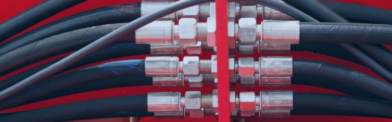
JIC fittings are a specific type of hydraulic fitting designed with a 37-degree flare seating surface. This unique angle is engineered to create a metal-to-metal seal, which is essential for maintaining a secure and leak-free connection, particularly in high-pressure applications. The design of JIC fittings makes them highly reliable and effective in preventing leaks, which is crucial in systems that handle high-pressure fluids. This metal-to-metal contact ensures a tight seal without the need for additional sealants, which simplifies maintenance and enhances reliability.

The development of JIC fittings dates back to World War II. During this period, the need for standardized hydraulic connections in military equipment became apparent. The military required robust and reliable fittings that could be easily manufactured and consistently meet stringent performance standards. As a result, the Joint Industry Council was formed to create a standardized fitting that could be used across various military applications. The 37-degree flare design was chosen for its superior sealing capabilities and ease of production. Following the war, the effectiveness and reliability of JIC fittings led to their adoption in civilian industries.
The versatility and reliability of JIC fittings have made them a staple in many industries.
Agriculture: In the agricultural sector, JIC fittings are commonly used in hydraulic systems for tractors, harvesters, and other farm equipment.
Construction: Heavy machinery such as excavators, bulldozers, and cranes rely on hydraulic systems that incorporate JIC fittings.
Transportation: The transportation industry uses JIC fittings in the hydraulic systems of trucks, buses, and other vehicles.
Fluid Power Systems: JIC fittings are integral to fluid power systems, where they connect different components such as pumps, valves, and actuators.
Fuel Delivery Systems: In fuel delivery systems, JIC fittings ensure that fuel is transported efficiently and without leaks.
Size Specifications: JIC fittings are designed to accommodate a wide range of sizes, ensuring compatibility with various hydraulic systems. The sizes are typically denoted in dash numbers (e.g., -4, -6, -8), which correspond to the fitting’s outside diameter (OD) measured in sixteenths of an inch. This standardized sizing system allows for easy identification and interchangeability. For instance, a -4 JIC fitting has an OD of 1/4 inch, a -6 fitting has an OD of 3/8 inch, and so on. This sizing convention helps streamline the selection process, ensuring that the correct fitting size is chosen for each application. Additionally, the use of dash numbers simplifies inventory management and reduces the risk of using incompatible fittings.
The pressure rating of JIC fittings is a critical specification that varies depending on the size and material of the fitting.
Smaller Sizes: For smaller JIC fittings, such as those with dash numbers -4 or -6, the pressure ratings can be as high as 10,000 psi. These high-pressure ratings make them suitable for demanding applications in hydraulic systems that operate under extreme conditions.
Larger Sizes: Larger JIC fittings, such as those with dash numbers -12 or -16, typically have lower pressure ratings, around 6,000 psi. While still robust, these fittings are designed for applications where lower pressure thresholds are acceptable.
JIC fittings are engineered to operate effectively across a broad temperature range, which is crucial for maintaining the integrity and performance of hydraulic systems in various environments.
General Range: Typically, JIC fittings can function in temperatures ranging from -65°F to 400°F (-54°C to 204°C). This wide range accommodates both extremely cold and hot conditions, ensuring the fittings remain reliable under diverse operating scenarios.
Material-Specific Tolerances: The material of the JIC fitting significantly influences its temperature tolerance.
Stainless Steel: Stainless steel JIC fittings have the highest temperature tolerance, making them suitable for applications that experience extreme temperature fluctuations or high-temperature conditions.
Carbon Steel and Brass: While still effective, carbon steel and brass fittings generally have lower temperature tolerances compared to stainless steel. These materials are more suitable for applications where the temperatures are within moderate ranges.
JIC fittings are designed and manufactured to adhere to strict industry standards to ensure quality, safety, and compatibility. One of the primary standards for JIC fittings is the SAE J514, which outlines the design, dimensions, and performance requirements for 37-degree flare fittings. Additionally, this standard covers the technical aspects of JIC fittings, such as material specifications, dimensional tolerances, and performance benchmarks, ensuring that all fittings meet a consistent level of quality and reliability.
To further guarantee quality and performance, many JIC fittings are certified by internationally recognized organizations. Two of the most notable certifying bodies are the ISO (International Organization for Standardization) and ASTM (American Society for Testing and Materials).
ISO Certifications: ISO certification indicates that the JIC fittings meet international standards for quality management and environmental management systems. ISO standards, such as ISO 9001, ensure that the manufacturing processes for JIC fittings are optimized for quality control, consistency, and continuous improvement. This certification assures customers that the fittings are produced under stringent quality management systems.
ASTM Certifications: ASTM certification, such as ASTM B633, which pertains to electrodeposited coatings of zinc on iron and steel, signifies that the fittings meet specific material and performance criteria. ASTM standards ensure that the materials used in the production of JIC fittings have been rigorously tested and meet the required specifications for durability, corrosion resistance, and mechanical properties.

To meet the high standards set by organizations like SAE, ISO, and ASTM, JIC fittings undergo extensive testing during and after the manufacturing process. These tests are designed to ensure that the fittings can perform reliably in various demanding applications and environments.
Pressure Tests: Pressure testing is conducted to verify that the JIC fittings can withstand the maximum specified operating pressures without failure or leakage. This involves subjecting the fittings to pressures higher than their rated capacity to ensure they have an adequate safety margin.
Temperature Cycling Tests: Temperature cycling tests expose the fittings to extreme temperatures, both hot and cold, to evaluate their performance and durability under thermal stress. This testing ensures that the fittings can maintain their integrity and sealing capabilities across a wide temperature range.
Vibration Tests: Vibration testing simulates the conditions that fittings may encounter in applications with high levels of mechanical vibration. These tests assess the fittings’ ability to maintain a secure connection without loosening or leaking under continuous vibration.
In addition to these specific tests, JIC fittings may also undergo other types of evaluations, such as corrosion resistance tests, tensile strength tests, and fatigue tests. These comprehensive testing protocols ensure that the fittings meet or exceed industry standards, providing users with confidence in their performance and reliability.
One of the easiest ways to identify JIC fittings is through the identification marks that manufacturers often imprint on the fittings. These marks usually include critical information such as the size, material, and manufacturer. For example, a fitting might be marked with “JIC-08-SS” indicating a JIC fitting, size 8 (which corresponds to 1/2 inch), made of stainless steel. These markings help ensure that the correct fitting is used for specific applications, especially in environments where multiple types of fittings might be present.
Visual Identification: Another method to identify JIC fittings is through visual inspection. The most distinctive feature of a JIC fitting is the 37-degree flare angle, which can be seen at the end of the fitting where the connection is made. This flare creates a metal-to-metal seal, which is crucial for the fitting’s performance in high-pressure applications. Additionally, JIC fittings often have a hexagonal body, allowing for easy installation and removal using standard wrenches.
Accurate measurement is essential for identifying the correct size of JIC fittings, ensuring they fit properly and function correctly in hydraulic systems. The primary tools used for this purpose are calipers and thread pitch gauges.
Calipers: Calipers are used to measure the outside diameter (OD) of the fitting. To do this, place the caliper’s jaws around the fitting’s outer edge and read the measurement on the caliper’s scale. This measurement, typically given in inches or millimeters, will correspond to the dash number size of the fitting.
Thread Pitch Gauges: To measure the thread size accurately, a thread pitch gauge is used. This tool has multiple blades, each with a different thread pitch. To use it, match the fitting’s threads to the corresponding blade on the gauge until you find an exact fit. The thread pitch gauge will tell you the threads per inch (TPI) or the metric thread pitch, which helps verify the fitting’s thread specifications.
By using these measurement techniques, you can ensure that the correct JIC fitting is selected and installed. This process is critical for maintaining the integrity and reliability of hydraulic systems, preventing issues such as leaks, misalignment, or thread damage.
Proper installation of JIC fittings is essential for ensuring a secure and leak-free connection in hydraulic systems. Here’s a step-by-step guide:
Cleaning the Mating Surfaces: Before installation, thoroughly clean the mating surfaces of both the fitting and the connection point. Use a clean cloth and an appropriate solvent to remove any dirt, debris, or oils. This step is crucial to prevent contaminants from compromising the seal.
Aligning the Fitting Correctly: Ensure that the fitting and the mating part are properly aligned. Misalignment can cause undue stress on the connection, leading to leaks or fitting failure. Carefully hand-thread the fitting to check for smooth engagement before applying any torque.
Tightening to the Recommended Torque: Use a calibrated torque wrench to tighten the fitting to the manufacturer’s recommended torque specifications. Over-tightening can damage the threads or the flare, leading to leaks or fitting failure. Under-tightening can result in a weak seal, also causing leaks. Always refer to the torque specifications provided by the fitting manufacturer to ensure proper installation.
Inspection After Installation: Once installed, inspect the connection to ensure there are no visible gaps or misalignments. Check the fitting for any signs of stress or deformation, which could indicate improper installation.
Avoiding common installation mistakes can significantly enhance the reliability and longevity of JIC fittings. Here are some pitfalls to watch out for:
Using the Wrong Size Fitting: Ensure you select the correct size fitting for the application. Using an incorrect size can result in poor sealing and connection issues.
Not Cleaning the Mating Surfaces: Installing fittings on dirty or contaminated surfaces can lead to leaks and compromised connections. Always clean the mating surfaces before installation.
Improper Tightening: Over-tightening can damage the fitting and the mating component, while under-tightening can lead to inadequate sealing. Use a torque wrench to apply the correct amount of torque.
Skipping Visual Inspection: Failing to visually inspect the fitting after installation can result in missed alignment issues or other problems that could compromise the connection.
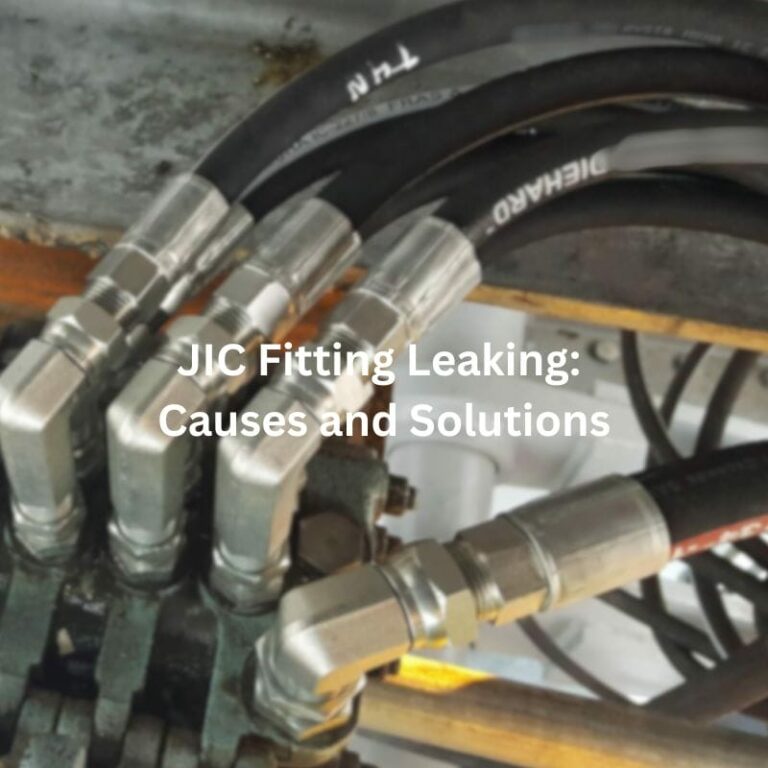
Addressing common issues with JIC fittings promptly can prevent minor problems from escalating into major failures. Here are some troubleshooting tips:
Leaks: If a fitting is leaking, first check if it has been properly tightened to the recommended torque. If tightening does not resolve the leak, inspect the flare and threads for damage. Replace any damaged fittings.
Thread Damage: Damaged threads can compromise the integrity of the connection. Inspect the threads for signs of wear or cross-threading. Replace fittings with damaged threads to ensure a secure connection.
Excessive Wear: Regularly check the fittings for signs of excessive wear, which can weaken the connection and lead to leaks. Replace worn fittings promptly.
Contamination: Contaminants can cause premature wear and damage to fittings. Ensure that all components are clean during installation and maintenance. Use filters and regular fluid changes to minimize contamination.

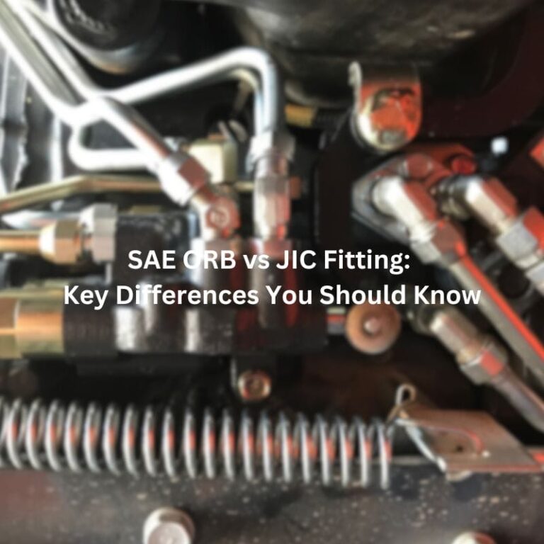
While both JIC and SAE fittings are commonly used in hydraulic systems, they have key differences that affect their compatibility and performance in specific applications.
Flare Angle: The primary difference between JIC and SAE fittings lies in the flare angle. JIC fittings have a 37-degree flare angle, whereas SAE fittings have a 45-degree flare angle. This difference means that the two types of fittings are not interchangeable and are designed for different sealing mechanisms.
Compatibility: Because of the different flare angles, JIC and SAE fittings are not compatible with each other. Attempting to use them interchangeably can lead to poor seals, leaks, and potential system failures.
JIC and NPT fittings have different sealing mechanisms, which influence their use and performance in hydraulic systems.
Sealing Mechanism: NPT (National Pipe Tapered) fittings rely on a tapered thread to create a seal. As the fitting is tightened, the taper compresses, creating a seal. However, this type of seal can be prone to leaks if not installed correctly and often requires the use of thread sealant or Teflon tape to ensure a tight seal.
Metal-to-Metal Seal: JIC fittings, on the other hand, provide a more reliable metal-to-metal seal through the 37-degree flare angle. This design reduces the risk of leaks, especially in high-pressure applications, by ensuring a tight and secure connection without the need for additional sealants.
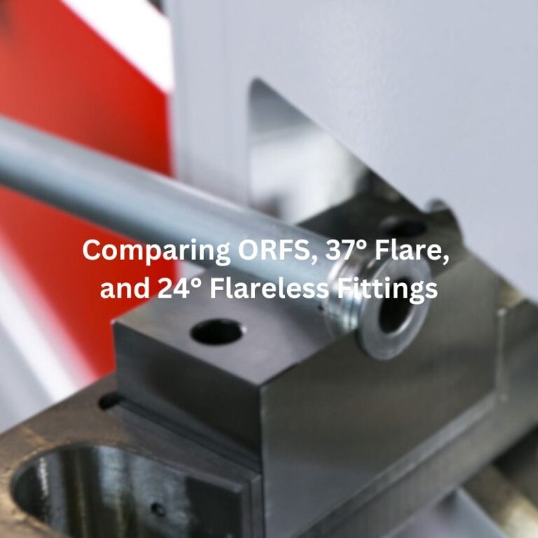
ORFS (O-ring Face Seal) fittings and JIC fittings both offer reliable sealing solutions but are suited to different types of applications.
Sealing Mechanism: ORFS fittings use an O-ring to create a seal. The O-ring sits in a groove on the face of the fitting, and when the fitting is tightened, the O-ring is compressed against a flat face on the mating part, creating a seal. This design offers superior leak resistance, especially in high-vibration and high-pressure applications.
Leak Resistance: The O-ring in ORFS fittings provides a more robust seal compared to the metal-to-metal seal of JIC fittings. This makes ORFS fittings particularly suitable for applications where leak prevention is critical, such as in hydraulic systems subject to high-pressure spikes or constant vibration.
In summary, understanding JIC fitting specifications is essential for ensuring the efficiency, safety, and reliability of hydraulic systems. By familiarizing yourself with the key specifications, standards, and installation practices, you can make informed decisions and optimize your hydraulic applications. For further assistance or specific questions, feel free to reach out to Topa experts or manufacturers.
JIC stands for Joint Industry Council, which standardized these fittings during World War II to ensure consistent, reliable hydraulic connections.
JIC fittings have a 37-degree flare angle, which creates a metal-to-metal seal for high-pressure applications.
No, JIC fittings cannot be used interchangeably with SAE fittings because SAE fittings have a 45-degree flare angle, making them incompatible.
Measure the outside diameter (OD) of the fitting and the thread pitch using calipers and a thread pitch gauge. The size is typically denoted in dash numbers representing sixteenths of an inch.
JIC fittings are commonly made from carbon steel, stainless steel, and brass. The choice of material depends on the application requirements, such as pressure, temperature, and corrosion resistance.
JIC fittings are used in various industries, including agriculture, construction, manufacturing, and transportation, for applications requiring durable, high-pressure hydraulic connections.
