Hydraulic systems rely heavily on various components to function efficiently, and one of these crucial components is hydraulic fittings. Understanding the different types of fittings available is essential for ensuring the reliability and safety of hydraulic systems. This article aims to delve into what JIC means in hydraulic fittings, exploring their design, applications, advantages, and more.
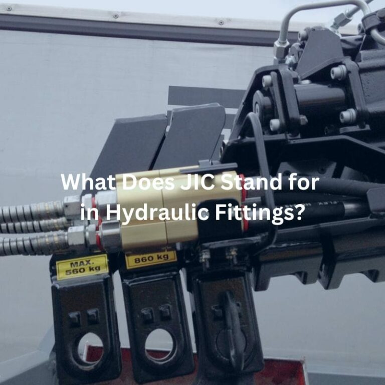
JIC stands for Joint Industry Council, an organization that was pivotal in developing standards for hydraulic connectors. This council’s primary goal was to create a standardized fitting that could be used across various industries, ensuring uniformity and compatibility.

One of the defining characteristics of JIC fittings is their 37-degree flare seating surface. This specific angle is critical because it ensures a tight seal between the fitting and the hydraulic hose or tube. The flare design allows the metal surfaces to mate perfectly when the fitting is assembled, creating a robust and leak-proof connection. The 37-degree angle was chosen after extensive testing and research, proving to be the optimal angle for durability and performance under high pressure.
JIC fittings were designed with compatibility and interchangeability in mind. This means that a JIC fitting from one manufacturer will fit and function correctly with a JIC fitting from another manufacturer, as long as both adhere to the standard specifications. This interchangeability reduces downtime in operations, as replacements and repairs can be made quickly without worrying about sourcing specific brands or custom parts.
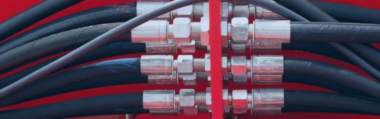
The standardization and reliability of JIC fittings have made them a popular choice in many applications. They are widely used in hydraulic systems across various sectors, including agriculture, construction, automotive, and oil and gas. Their ability to provide secure, leak-proof connections under high pressure makes them ideal for demanding environments. The versatility of JIC fittings also means they can be used in both stationary and mobile equipment, further broadening their application range.
JIC fittings are manufactured from a range of durable materials, each chosen for their specific properties that enhance the fitting’s performance:
Stainless Steel: Known for its excellent corrosion resistance and high strength, stainless steel JIC fittings are ideal for applications involving harsh environments or where hygiene is a concern, such as in the food and beverage or chemical industries.
Brass: Brass fittings offer good corrosion resistance and are easy to machine, making them a cost-effective choice for many standard hydraulic applications. They are often used in low to medium-pressure systems where durability and ease of installation are prioritized.
Carbon Steel: Carbon steel fittings are renowned for their high strength and toughness, making them suitable for high-pressure applications. They are often coated or plated to enhance their corrosion resistance, ensuring longevity in demanding conditions.
JIC fittings are designed to withstand high-pressure conditions, a critical requirement in hydraulic systems. The exact pressure tolerance can vary depending on the material and size of the fitting, but generally, JIC fittings are rated for pressures up to 10,000 psi or more. This high-pressure tolerance ensures that the fittings can handle the demands of various hydraulic applications without failing.
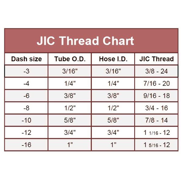
JIC fittings are available in a wide range of sizes to accommodate different hose and tube diameters. Common sizes include 1/8″, 1/4″, 3/8″, 1/2″, 3/4″, and 1″, among others. This variety ensures that there is a JIC fitting suitable for almost any hydraulic system requirement, providing flexibility in system design and maintenance.
JIC fittings conform to rigorous standards, ensuring their performance and safety:
SAE J514: This standard, developed by the Society of Automotive Engineers (SAE), specifies the dimensions, performance, and testing requirements for 37-degree flare fittings. Compliance with SAE J514 ensures that JIC fittings are compatible with other fittings and components made to the same standard, facilitating easy integration and replacement.
ISO 8434-2: The International Organization for Standardization (ISO) standard 8434-2 covers the general and dimensional requirements for 37-degree flare fittings. Adherence to this standard guarantees that the fittings meet international quality and safety benchmarks, making them suitable for global applications.
When working with hydraulic systems globally, understanding the differences between JIC fittings and other international standards is crucial for proper system design, maintenance, and component selection. This comparison highlights the key differences in design, application, and compatibility between JIC and other major hydraulic fitting standards.
Sealing Mechanism
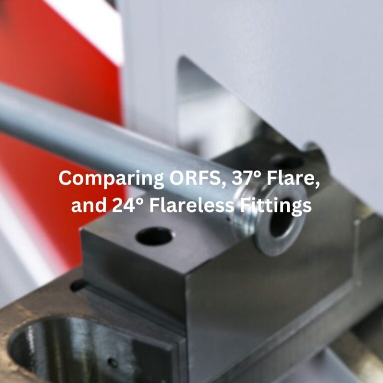
JIC Fittings: Utilize a 37° flared sealing surface where metal-to-metal contact creates the seal. The male fitting has a 37° cone that mates with the female 37° flare.
Metric Fittings: Typically employ a 24° cone sealing system (DIN 2353/ISO 8434-1) where the cutting ring or ferrule creates two sealing points between the fitting body and tube.
Thread Type
JIC Fittings: Use Unified National Fine (UNF) threads with a straight (parallel) thread form measured in inches.
Metric Fittings: Use metric straight threads measured in millimeters with standardized pitch (e.g., M14×1.5, M16×1.5).
Size Designation
JIC Fittings: Sized by dash numbers representing 1/16-inch increments (e.g., -4 equals 4/16 or 1/4 inch).
Metric Fittings: Directly designated by their nominal outer diameter in millimeters (e.g., 6mm, 8mm, 10mm).
Pressure Ratings
JIC Fittings: Generally rated for medium to high-pressure applications, typically up to 5,000-6,000 PSI depending on size.
Metric Fittings: Available in light (L), heavy (S), and very heavy (LL) series with pressure ratings from 3,600 PSI to over 9,000 PSI depending on the series and size.
Global Adoption
JIC Fittings: Predominantly used in North America and in industries with American origins.
Metric Fittings: Standard throughout Europe, Asia, and most developing markets.

Sealing Mechanism
JIC Fittings: 37° metal-to-metal flare seal.
BSPP Fittings: Parallel thread (G) that requires a bonded seal, O-ring, or other sealing element compressed against a 30° chamfer or flat face.
BSPT Fittings: Tapered thread (R) that creates a seal through thread deformation, often requiring thread sealant.
Thread Form
JIC Fittings: 60° thread angle with UNF thread form.
BSP Fittings: 55° Whitworth thread form with rounded roots and crests, giving a distinctive appearance.
Size Designation
JIC Fittings: Dash number system based on 1/16-inch increments.
BSP Fittings: Nominal pipe sizes in inches (e.g., 1/4″, 1/2″), which don’t directly correspond to actual thread dimensions.
Applications
JIC Fittings: Common in mobile hydraulics, industrial machinery, and aerospace applications.
BSP Fittings: Prevalent in European hydraulic systems, Commonwealth countries, and marine applications.
Interchangeability
JIC and BSP fittings are not interchangeable despite some having similar dimensions. For example, a 9/16″-18 JIC thread and G 1/4 BSPP have close dimensions but different thread forms and sealing methods.

Sealing Mechanism
JIC Fittings: 37° flare with metal-to-metal contact.
NPT Fittings: Tapered thread that creates a seal through thread deformation, typically requiring PTFE tape or liquid thread sealant.
Thread Type
JIC Fittings: Straight UNF threads that don’t participate in sealing.
NPT Fittings: Tapered threads with a 1° 47′ taper angle that creates the seal throughan interference fit.
Reusability
JIC Fittings: Can be disconnected and reconnected multiple times without significant degradation of the sealing surface.
NPT Fittings: Each assembly/disassembly cycle can degrade the sealing capability, making them less ideal for systems requiring frequent maintenance.
Pressure Consistency
JIC Fittings: Provide consistent pressure ratings and predictable torque requirements.
NPT Fittings: Sealing effectiveness can vary based on installation technique and thread sealant application.
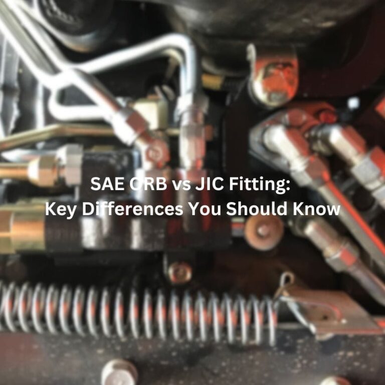
Sealing Mechanism
JIC Fittings: 37° flare metal-to-metal seal.
SAE STOR Fittings: O-ring compressed in a gland to create the seal, with straight threads only providing mechanical connection.
Pressure Capability
JIC Fittings: Good for medium to high-pressure applications.
SAE STOR Fittings: Excellent for high-pressure applications with superior vibration resistance due to the elastomeric seal.
Assembly Considerations
JIC Fittings: Require proper torque to ensure the flare seats correctly without over-tightening.
SAE STOR Fittings: Require careful O-ring installation and prevention of damage during assembly.
Common Applications
JIC Fittings: Widely used across various hydraulic applications.
SAE STOR Fittings: Common in mobile equipment where vibration resistance is critical.
|
Feature |
JIC |
Metric |
BSP |
NPT |
SAE STOR |
|
Sealing Method |
37° flare metal-to-metal |
24° cone with cutting ring |
BSPP: Bonded seal/O-ring BSPT: Thread deformation |
Thread deformation with sealant |
O-ring compression |
|
Thread Type |
Straight UNF threads |
Straight metric threads |
55° Whitworth thread form |
Tapered 1°47′ threads |
Straight UNF threads |
|
Thread Angle |
60° |
60° |
55° |
60° |
60° |
|
Size Designation |
Dash numbers (-4 = 1/4″) |
Millimeters (6mm, 8mm) |
Inch fractions (1/4″, 1/2″) |
Inch fractions (1/4″, 1/2″) |
Dash numbers |
Identifying JIC fittings accurately is crucial for ensuring compatibility and proper functioning within hydraulic systems. This section provides detailed guidance on visual identification tips, measuring techniques, and common mistakes to avoid.
Markings on the Fittings
JIC fittings often have specific markings that help identify their type and size. These markings can include:
Manufacturer’s Name or Logo: This helps trace the origin of the fitting.
Size Designation: Typically marked in inches or fractions of an inch, indicating the fitting size.
Standards Compliance: Marks indicating compliance with standards such as SAE J514 or ISO 8434-2.
Flare Angle
The most distinctive feature of JIC fittings is the 37-degree flare angle. This angle is critical for identification and can often be recognized visually by those familiar with hydraulic fittings. The flare angle ensures a proper metal-to-metal seal, distinguishing JIC fittings from other types, such as SAE 45-degree fittings.
Shape and Construction
JIC fittings have a unique shape due to their flare design. They typically consist of a body, sleeve, and nut. The fitting’s body will have a conical surface designed to mate with the 37-degree flared tube. Familiarity with the overall shape and construction can aid in quick identification.
Using a Caliper
A caliper is an essential tool for measuring the critical dimensions of JIC fittings:
Outer Diameter (OD): Measure the OD of the fitting to determine its size.
Flare Diameter: Measure the diameter of the flared end of the tube or fitting.
Thread Pitch: Use a thread pitch gauge to measure the threads per inch (TPI) or the distance between threads. This helps differentiate JIC threads from other thread types.
Using a Protractor or Flare Gauge
To measure the flare angle accurately:
Misidentifying Flare Angles
One of the most common mistakes is confusing JIC fittings with other flare fittings, such as SAE 45-degree fittings. To avoid this:
Ignoring Thread Pitch
JIC fittings have specific thread pitches that must be matched correctly. Mistaking thread pitches can lead to incompatible connections. Use a thread pitch gauge to measure and match the correct pitch accurately.
Overlooking Markings
Markings on fittings provide valuable information about their size and compliance. Ignoring these can lead to incorrect identification. Always check for and interpret these markings correctly.
Not Measuring Properly
Relying on visual identification alone without precise measurement can result in errors. Always use appropriate tools like calipers, protractors, and thread pitch gauges to ensure accurate identification.
Proper installation and maintenance of JIC fittings are essential for ensuring secure, leak-free connections in hydraulic systems. This section provides a detailed guide on the installation process and essential maintenance practices.
Cutting the Tube
Creating a 37Degree Flare
Assembling the Fitting
Final Tightening
Regular Inspections
Leak Detection
Preventive Maintenance
Documentation
Proper installation and regular maintenance of JIC fittings are critical for ensuring reliable, leakfree hydraulic connections. Following the correct procedures for cutting, flaring, and assembling the fittings, and adhering to a routine maintenance schedule, will extend the life of the fittings and maintain the efficiency and safety of the hydraulic system. These practices help prevent unexpected failures and costly downtime, ensuring optimal performance in demanding applications.
In summary, understanding the functionality and benefits of JIC fittings is critical for anyone working with hydraulic systems. Their reliable sealing mechanism, highpressure tolerance, and versatility make them an indispensable component in various industries. By choosing the appropriate fittings and adhering to proper installation and maintenance protocols, users can ensure that their hydraulic systems remain efficient, reliable, and longlasting.
JIC stands for Joint Industry Council. These fittings are known for their 37degree flare design, which ensures a reliable, leakproof connection in hydraulic systems.
The main advantages of JIC fittings include their highpressure tolerance, reliable metaltometal seal, ease of assembly and disassembly, versatility in various applications, and reusability.
JIC fittings can be identified by their 37degree flare angle, specific markings indicating size and standards compliance, and their unique shape and construction. Using a protractor or flare gauge can help confirm the 37degree angle.
JIC fittings are typically made from stainless steel, brass, or carbon steel. These materials are chosen for their durability, corrosion resistance, and ability to withstand high pressures.
JIC fittings conform to standards such as SAE J514 and ISO 84342. These standards ensure that the fittings meet specific performance and safety requirements, guaranteeing compatibility and reliability.
Regular maintenance of JIC fittings includes visual inspections for wear and tear, checking for leaks, ensuring proper tightness.
