Mastering Ball Valve Operation banner

Mastering Ball Valve Operation: A Complete Guide

A well-functioning ball valve ensures that fluids are controlled precisely, minimizing wastage, improving flow rates, and preventing dangerous leaks or system malfunctions. Proper operation also prevents damage to downstream equipment and protects against system failures that could lead to costly downtime, safety incidents, or regulatory non-compliance.

Understanding Ball Valve Construction and Components  

Core Components of a Ball Valve

A ball valve is a simple yet effective device, and its reliable performance depends on several key components, each of which plays a vital role in its operation. Understanding these components will help you appreciate how the valve works and how to maintain or troubleshoot it.

Valve Body:

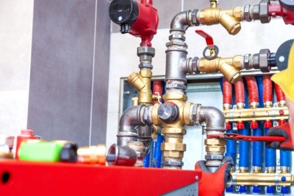
The valve body is the outer casing that holds all the internal components together. It is the largest part of the valve and is designed to withstand the pressure and temperature conditions of the system. The body provides the connection to the pipeline and serves as the support for the other internal components, ensuring they function properly under pressure.

Ball:

The ball is the central component of the valve and controls the flow of fluid. It has a hole or port through the middle, and by rotating 90 degrees, the ball either aligns the hole with the pipeline to allow fluid flow or turns the hole away from the flow path to block it. The ball is typically made of materials like stainless steel, brass, or a ceramic compound, depending on the valve’s application.

Seats:

The valve seats are placed around the ball and provide the sealing surface that ensures the valve creates a tight shut-off when closed. The seats are designed to create a pressure-tight seal against the ball to prevent leakage. They can be made from various materials, such as PTFE (Teflon), PEEK, or elastomers, depending on the media being controlled and the temperature and pressure requirements.

Stem:

The stem connects the valve handle or actuator to the ball inside the valve. It transmits the motion of the actuator (manual or automated) to the ball, allowing it to rotate. The stem is usually fitted with seals to prevent leaks of fluids around it. This component is essential for ensuring the valve opens and closes smoothly.

Actuator:

The actuator is the mechanism used to operate the ball valve. It can be manual (a handwheel or lever), electric (electrically powered motors), pneumatic (air-driven), or hydraulic (fluid-driven). Actuators make it easier to operate valves, especially in systems where the valve is located in hard-to-reach places or needs to be automated for efficiency and safety.

Ball Valve components

Types of Ball Valves

Ball valves come in several configurations, each designed for different applications. The operation of these valves can vary based on their design and the specific needs of the system.

Standard Ball Valve:

The most common ball valve type, where the ball “floats” and is held in place by the pressure of the fluid. The ball rotates freely inside the valve body. This type of valve is ideal for on/off control in systems with moderate pressure and flow.

Trunnion Ball Valve:

This type of ball valve uses a trunnion-mounted ball that is supported by bearings on both sides, making it more stable under high-pressure conditions. This design reduces the load on the valve seats and is often used in larger valves or systems with higher flow rates and pressures, such as in the oil and gas industry.

Floating Ball Valve:

In a floating ball valve, the ball is not mounted but is instead “floating” and held in place by the pressure of the fluid. This design is more cost-effective for smaller valves and systems with moderate pressure. The floating ball design provides better sealing under low-pressure conditions but is not as suitable for high-pressure applications.

Materials Used in Ball Valves

The materials used in the construction of ball valves are critical to their performance, longevity, and ability to withstand the demanding conditions of different industrial environments.

Stainless Steel:

Stainless steel is one of the most commonly used materials for ball valves due to its excellent corrosion resistance, strength, and durability. It is ideal for handling harsh fluids, high temperatures, and corrosive environments. Stainless steel is often used in the chemical, food processing, and water treatment industries.

Brass:

Brass is another popular material, especially for smaller ball valves used in residential or light industrial applications. It is durable, corrosion-resistant, and offers good thermal conductivity, making it suitable for moderate temperature and pressure conditions. Brass valves are commonly used in plumbing and HVAC systems.

PVC (Polyvinyl Chloride):

PVC ball valves are used in applications involving water or low-pressure systems, such as irrigation, pool systems, and wastewater treatment. PVC is lightweight, corrosion-resistant, and cost-effective, though it is not suitable for high-temperature or high-pressure environments.

How Ball Valves Operate

Basic Function of a Ball Valve

A ball valve is a quarter-turn valve used to control the flow of fluids in a pipeline system. The core component of the valve is the ball, a spherical element with a hole or port through the center. The operation of the ball valve relies on this ball rotating within the valve body to either allow or stop fluid flow.

Opening and Closing Mechanism:

When the valve handle or actuator is turned, the ball inside the valve rotates 90 degrees. In the open position, the hole in the ball aligns with the pipeline, creating an unobstructed flow path. When the valve is closed, the ball is rotated so that the hole is perpendicular to the flow path, effectively blocking the flow of fluid.

Control of Fluid Flow:

Ball valves are typically designed for on/off control, meaning they are either fully open or fully closed. However, ball valves with adjustable flow controls can be used for throttling applications, where the valve is partially open, and fluid flow is modulated. The ball’s smooth surface and rotation allow for easy, efficient control of fluid passage with minimal pressure drop and flow resistance.

Valve Operation Modes

Ball valves can be operated manually or automatically, depending on the application and system requirements. Understanding the different modes of operation is essential for ensuring efficient valve control in various settings.

Manual Operation:

In manual operation, the ball valve is typically operated by a lever, handwheel, or gear actuator, which requires human intervention to turn the valve. This type of operation is common in smaller systems where ease of operation and control is sufficient, such as in residential plumbing, small industrial systems, and some HVAC applications.

Lever Operation: The lever is attached directly to the valve stem and is turned by hand to rotate the ball inside the valve. This simple form of operation is used for smaller, low-pressure systems.

Handwheel Operation: A handwheel is connected to the valve stem and provides greater mechanical advantage to open or close the valve. This is used for larger valves where more torque is required.

Gear Actuator: A gear actuator is often used when precise control and higher torque are needed. The gear mechanism helps with turning the valve stem in industrial settings or where the valve is hard to access.

Automated Operation:

For more complex or remote-controlled systems, ball valves are operated by actuators, which can be pneumatic, electric, or hydraulic. Automated operation is essential in large-scale industrial applications where valves need to be operated frequently, precisely, and often remotely.

Pneumatic Actuators: Pneumatic actuators use compressed air to move the valve ball. These actuators are fast, reliable, and widely used in automated systems, particularly in industries like oil & gas, chemical processing, and water treatment.

Electric Actuators: Electric actuators are powered by electricity and provide precise, controlled movement. They are ideal for environments where precise positioning and adjustable flow control are required. These actuators are often used in systems that require frequent cycling and are commonly found in control systems and automation processes.

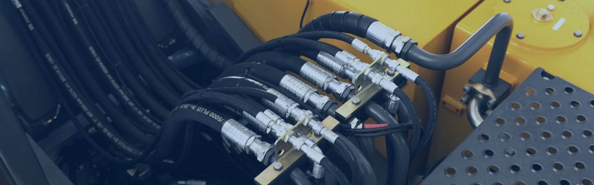
Hydraulic Actuators: Hydraulic actuators use pressurized hydraulic fluid to drive the movement of the valve. These are ideal for high-pressure applications, such as in power plants, refineries, and large industrial systems where high force is needed to operate the valve.

The type of actuator used affects the response time, precision, and power requirements of the valve, and each type is suited to different application conditions and operational needs.

ball valve work

Fluid Flow Control

The way a ball valve is designed influences its ability to control fluid flow. Two primary factors are critical in determining the flow characteristics of a ball valve: the type of ball valve (full-port or reduced-port) and its size.

Full-Port vs. Reduced-Port Ball Valves:

Full-Port Ball Valves: In full-port ball valves, the diameter of the ball’s hole is the same size as the pipe it is connected to. This design allows for unrestricted flow and minimal pressure drop across the valve. Full-port valves are ideal for applications requiring maximum flow rates and low resistance, such as in large piping systems, oil & gas pipelines, and water distribution systems.

Reduced-Port Ball Valves: In reduced-port ball valves, the ball’s hole is smaller than the pipe diameter, which results in some restriction of the flow when the valve is open. While they are often used for applications where flow rates can be controlled, reduced-port valves may cause higher pressure drops due to the smaller opening. These valves are often used in smaller systems or where less flow is needed.

Impact of Valve Size on Flow Rate and System Pressure:

The size of the ball valve has a direct impact on flow rate and pressure. Larger valves generally allow for higher flow rates and are suitable for high-demand systems with large volumes of fluid. Conversely, smaller valves provide better control over fluid flow and are often used in more confined spaces or for precise control in smaller systems.

Large Ball Valves: Larger ball valves are ideal for high-flow applications, where large volumes of fluid need to be regulated or stopped, such as in pipelines, industrial plants, and water treatment systems.

Small Ball Valves: Smaller ball valves are used for applications that require tight control over flow, such as in laboratory settings, pharmaceutical processes, or HVAC systems.

Key Factors That Affect Ball Valve Operation  

Pressure and Temperature

Impact of Pressure and Temperature on Valve Performance:

Ball valves are designed to operate within certain pressure and temperature limits, which vary depending on the materials used in the valve construction and the type of valve. Exceeding these limits can cause the valve to malfunction or even fail.

Pressure:

The pressure inside the pipe has a significant impact on the operation of the ball valve. At high pressure, the valve must withstand the force exerted by the fluid. If the pressure exceeds the valve’s rating, the valve body, ball, or seals can become deformed or damaged, leading to leakage, difficulty in operation, or complete failure to open or close.

A ball valve with an insufficient pressure rating will struggle to perform its intended function, resulting in system inefficiency and potential damage to downstream equipment.

Temperature:

Temperature extremes also play a vital role in valve performance. High temperatures can cause thermal expansion of materials, leading to leakage around seals or deformation of valve components. In contrast, extremely low temperatures may cause materials like elastomers or plastics to become brittle, leading to cracking or failure of seals and gaskets.

Operating Pressure Ratings and Temperature Limitations:

Most ball valves are rated with a maximum working pressure and temperature range. For example, a valve designed for use in high-temperature environments may feature heat-resistant seals and materials like stainless steel or alloys that can handle temperatures up to 800°F or higher.

It is essential to ensure that the ball valve selected for an application falls within the pressure and temperature limits required by the system to avoid damage and maintain optimal operation.

Seals and Gaskets

Role of Seals and Gaskets:

Seals and gaskets play a crucial role in ensuring that the ball valve performs correctly by preventing leaks and maintaining a tight seal around the ball and valve body. These components are essential in preventing fluid from escaping when the valve is in the closed position, and they also help maintain the correct internal pressure and flow characteristics when the valve is open.

Impact of Damaged or Worn Seals:

Seals and gaskets can wear down due to continuous exposure to high pressure, high temperature, or aggressive fluids. Once seals are damaged or degraded, they can no longer form a reliable barrier, resulting in fluid leakage around the valve body or stem.

Leaking Around the Valve Body: If the seals between the valve body and the ball are compromised, the valve will leak when in the closed position. This can cause system inefficiencies and even safety hazards in certain applications.

Worn Stem Seals: Worn seals around the valve stem can also lead to leakage, especially in higher-pressure applications where stem seals are critical in maintaining the pressure integrity of the valve.

Maintaining Seals and Gaskets: Regular inspection and replacement of worn seals and gaskets can prevent leaks and ensure continued smooth operation of the valve. Use of the right materials for seals and gaskets based on the specific fluid, pressure, and temperature conditions is also crucial for valve longevity.

Valve Alignment

Importance of Proper Alignment for Optimal Valve Function:

Proper valve alignment ensures that all components of the ball valve function correctly, without excess wear or damage. Misalignment can lead to improper sealing, friction, and uneven wear on valve components, which in turn can reduce the valve’s efficiency and lifespan.

Misalignment Issues:

Misalignment often occurs during installation, and common causes include improper handling, incorrect mounting angles, or errors in the piping system design. When a valve is misaligned, the ball may not rotate freely, resulting in resistance during operation. This can lead to increased wear on the valve stem and seals, as well as difficulty in opening and closing the valve. Misalignment may also cause the valve ball to not fully seat, resulting in fluid leaks even when the valve is in the closed position.

Preventing Misalignment:

Careful installation procedures, including correct torque application and alignment of the valve to the pipeline, are critical to ensure proper valve function. Ensuring that the valve is properly aligned with the surrounding piping can prevent these issues and reduce the likelihood of operational problems in the future.

Lubrication

How Lubrication Affects Ball Valve Operation:

Lubrication plays an essential role in ensuring smooth operation of the ball valve, particularly in valves with manual actuators or those used in high-pressure and high-temperature applications. Lubrication reduces friction between the valve ball and the valve seat, making it easier to open or close the valve and reducing wear on these components.

Impact of Proper Lubrication:

Proper lubrication ensures that the valve components move smoothly, prevents corrosion, and reduces the chances of seizing or sticking due to friction. This is especially important in environments where valves are exposed to extreme temperatures, pressure fluctuations, or corrosive fluids.

Best Practices for Lubrication:

Lubrication Frequency: Regular lubrication schedules should be followed based on manufacturer recommendations and the operating conditions of the valve.

Choosing the Right Lubricant: The choice of lubricant depends on the operating temperature, pressure, and fluid being controlled. High-performance lubricants, such as synthetic oils or greases designed for extreme conditions, may be required for valves operating in harsh environments.

Avoid Over-lubrication: Excess lubricant can cause dirt and debris to accumulate, leading to valve fouling. It is essential to apply the correct amount of lubricant to avoid potential issues.

Conclusion

We encourage readers to assess their ball valves regularly for these key factors, including pressure and temperature conditions, seal wear, alignment, and lubrication status. Regular maintenance, timely repairs, and appropriate lubrication practices are essential to ensure the longevity and reliability of ball valves.


FAQ

What is a ball valve and how does it work?

A ball valve is a type of valve that uses a spherical ball to control the flow of fluid through a pipe. The ball has a hole in the center, and when aligned with the pipe, fluid flows freely. When rotated 90 degrees, the hole is perpendicular to the pipe, blocking the flow.

What are the common causes of ball valve failure?

Common causes of ball valve failure include high pressure, extreme temperature, worn-out seals and gaskets, misalignment, and insufficient lubrication. Regular maintenance and proper installation can prevent most of these issues.

How do I know if my ball valve is failing?

Signs of a failing ball valve include leaks around the valve body or stem, difficulty in opening/closing the valve, unusual noises (like grinding or squeaking), and inconsistent flow or pressure.

What is the role of lubrication in ball valve operation?

Lubrication helps reduce friction between the valve ball and seat, ensuring smooth operation. Proper lubrication also prevents corrosion and extends the valve’s lifespan.

What materials are used in ball valves?

Common materials for ball valves include stainless steel, brass, PVC, and alloys, chosen based on the application. Stainless steel is popular for high-pressure or corrosive environments, while PVC is commonly used for low-pressure and non-corrosive fluids.

How do pressure and temperature affect ball valve operation?

Pressure and temperature extremes can affect the performance of ball valves. High pressure can cause leaks or deformation of valve components, while excessive temperature can degrade seals and gaskets, causing leaks or valve failure.

Types of Hose Ferrules banner

Types of Hose Ferrules: Key to Secure Hose Assemblies

In hydraulic and industrial applications, hose assemblies are often subjected to extreme conditions—high-pressure systems, corrosive fluids, and intense vibrations—making the role of hose ferrules all the more important. These small but powerful components are designed to provide a tight, durable seal that ensures hoses stay securely attached to fittings, preventing leakage and potential system breakdowns.

What Is a Hose Ferrule?

A hose ferrule is a metal or plastic component that is used to secure the end of a hose to a fitting in order to create a tight, leak-proof seal. Ferrules are typically placed over the hose and then crimped or compressed to tightly hold the hose against the fitting, ensuring that the two components are firmly connected. They are essential in creating a reliable and durable connection in hose assemblies, especially in systems where high pressure, vibration, or extreme conditions are present.

Basic Function

The primary function of a hose ferrule is to secure the hose to the fitting in a way that prevents leakage and ensures the integrity of the connection. The ferrule is slid over the hose, usually after the hose has been cut to the required length and the fitting is placed at the other end. Once positioned, the ferrule is crimped or compressed using specialized tools, such as a crimping machine, to tightly grip the hose and the fitting. This process ensures that the hose is securely fastened, preventing any fluid or gas from leaking out of the connection.

Ferrules work by applying equal pressure around the hose, allowing the fitting to be securely held in place. This is particularly important in high-pressure systems, where leaks can lead to system failure, costly downtime, or even dangerous accidents. The hose ferrule creates a seal that withstands the internal pressure within the hose, effectively preventing leaks at the connection point. Depending on the application, ferrules may be made from materials like stainless steel, brass, or aluminum, which provide strength, corrosion resistance, and durability.

Tractor hose ferrule manufacturer in China

Why They Are Important

Hose ferrules are critical to the performance, durability, and safety of hose assemblies. Without a properly installed ferrule, hoses may become loose or detached from their fittings, leading to potential leaks or system malfunctions. In industrial settings, such as hydraulic, automotive, or chemical systems, even a small leak can cause significant damage, harm workers, or lead to costly repairs. The ferrule ensures that the hose and fitting remain tightly connected, preventing these risks.

Additionally, hose ferrules contribute to the efficiency of fluid and gas transfer within the hose assembly. A secure connection ensures that fluid flows freely without resistance or loss, improving the overall efficiency of the system. Moreover, the longevity of the hose assembly is greatly extended when ferrules are properly selected and maintained. In short, hose ferrules are integral to maintaining a secure, reliable, and efficient hose system, supporting safety, operational effectiveness, and cost savings across various industries.

Components of Hose Assemblies and the Role of Ferrules

Hose assemblies are crucial in many industrial systems where the transport of fluids, gases, or hydraulic pressure is needed. These assemblies are made up of several key components, each playing a specific role in ensuring the hose system functions safely and efficiently. The main components of a typical hose assembly include the hose, the fitting, the ferrule, and the coupling. Together, these components work in harmony to create a reliable, leak-proof connection.

Overview of Hose Assemblies

Hose: The hose is the flexible conduit that carries fluids or gases from one point to another in a system. It is typically made from materials like rubber, thermoplastic, or metal braided layers to provide flexibility and resistance to abrasion, pressure, and temperature. The hose’s inner lining is designed to handle specific types of fluids or gases, while the outer layers provide reinforcement and protection.

Fitting: A fitting is a mechanical component that connects the hose to another system component, such as a valve, pump, or machinery. Fittings are typically made of materials like stainless steel, brass, or aluminum and come in various shapes, sizes, and configurations, such as elbows, tees, and straight connectors. The fitting ensures that the hose securely connects to the system and provides a leak-tight seal.

Ferrule: A ferrule is a small yet vital component used to secure the hose to the fitting. It is usually made from metal, such as stainless steel, or other materials like brass or plastic, and is placed over the hose where it meets the fitting. The ferrule is then crimped or compressed to create a tight seal that prevents fluid or gas leakage. The ferrule also helps to reinforce the hose and prevent the fitting from being damaged during operation.

Coupling: A coupling is used in some hose assemblies to provide a quick disconnect or to facilitate easier connection and disconnection between the hose and the equipment. Couplings often incorporate valves to prevent leakage when disconnected.

Ferrule’s Function in Assemblies

The ferrule’s primary function is to securely attach the hose to the fitting, ensuring that the connection is tight and leak-proof. When installed, the ferrule is placed around the hose and fitting and is then crimped or compressed using a crimping tool. This process applies pressure, creating a secure bond between the hose and the fitting, which prevents the hose from slipping off or leaking.

Ferrules are critical in maintaining the integrity of hose assemblies, especially in high-pressure systems, where even the slightest gap can lead to dangerous leaks. By tightly compressing the hose against the fitting, the ferrule ensures that the connection remains secure under a wide range of conditions, including fluctuating pressures, vibrations, and temperature changes. Without the ferrule, the hose could easily detach or loosen, leading to potential failure in the system.

Interaction with Other Components

The ferrule’s role is intertwined with that of the hose and fitting, as it directly interacts with both to ensure a leak-proof, high-performance hose assembly.

Hose and Ferrule Interaction: The hose itself is designed to handle specific pressures, temperatures, and types of fluid or gas. The ferrule, when properly installed, compresses the hose in a way that maximizes the contact area between the hose and fitting. This increases the strength of the connection and helps distribute pressure evenly, reducing the chances of hose failure. The ferrule also reinforces the hose by preventing it from deforming under pressure or exposure to environmental stressors.

Fitting and Ferrule Interaction: The fitting is responsible for connecting the hose assembly to the rest of the system. It must be compatible with the ferrule to ensure a proper fit. The ferrule works with the fitting to create a mechanical seal that can withstand high pressures, minimizing the risk of leaks. In addition, the ferrule provides a cushioning effect that prevents damage to the fitting due to excessive pressure or vibration. The correct choice of ferrule material is crucial, as it must be compatible with the material of the fitting to avoid issues like corrosion or wear.

Types of Hose Ferrules

Crimp Ferrules

Crimp ferrules are the most commonly used type of ferrule in industrial hose assemblies. These ferrules are typically made of metal (such as stainless steel or brass) and are designed to be crimped tightly around the hose and fitting using a crimping tool.

How They Work: When a crimp ferrule is placed over the hose, a crimping tool is used to compress the ferrule, forcing it to tightly grip both the hose and the fitting. This creates a secure, leak-proof connection that is resistant to pressure and external stress. Crimp ferrules are often used in high-pressure hydraulic systems and other applications where a strong, permanent connection is required.

Advantages:

Strong and Durable: Crimp ferrules provide a high level of security, even in systems that experience high pressure, vibration, or harsh operating conditions.

Leak Prevention: The tight seal created by crimping ensures that no fluids or gases escape from the connection.

Permanent Connection: Once crimped, the ferrule forms a permanent, tamper-resistant bond, ensuring the integrity of the hose assembly.

Crimp ferrules are ideal for applications that require high pressure resistance, such as in hydraulic systems, fuel systems, and industrial machinery.

Reusable Ferrules

Reusable ferrules are designed for systems where the hose connections need to be disassembled and reassembled without compromising the connection’s integrity. Unlike crimp ferrules, reusable ferrules can be removed, inspected, and reattached multiple times, making them ideal for applications where hoses need to be replaced or serviced regularly.

How They Work: Reusable ferrules are typically designed with threads, a clamping mechanism, or a compression ring that can be easily tightened or loosened without requiring specialized crimping tools. After the ferrule is loosened, the hose can be removed, inspected, and replaced if needed, then the ferrule can be reattached to the fitting.

Advantages:

Cost-Effective: Since they can be reused, these ferrules are more economical in systems where hoses require frequent changes.

Ease of Maintenance: Reusable ferrules allow for easier maintenance and servicing of hose assemblies without the need to replace the ferrule each time the hose is changed.

Flexibility: They can be disassembled for cleaning, inspection, or part replacement, reducing downtime and increasing operational efficiency.

Reusable ferrules are commonly used in industries like automotive, food and beverage, or pharmaceutical applications where hoses are regularly replaced or cleaned.

Push-on Ferrules

Push-on ferrules are a more straightforward type of ferrule. They are typically used in low-pressure applications or where the connection does not need to withstand extreme pressure or stress. Push-on ferrules are made to fit over the hose and fitting with minimal effort, requiring no crimping or additional tools.

How They Work: Push-on ferrules are designed with a flexible, tight-fitting mechanism that “snaps” or slides over the hose and fitting. Once in place, they create a secure enough connection to hold the hose in place under moderate conditions. However, these ferrules are generally not suitable for high-pressure systems.

Advantages:

Ease of Installation: Push-on ferrules are easy to install and remove, making them ideal for quick hose changes in low-pressure applications.

Cost-Effective: Since they do not require crimping tools, they are more affordable than other types of ferrules.

Light-Duty Use: These ferrules are best for non-critical applications where the pressure and fluid types do not require the additional durability provided by crimp or reusable ferrules.

Push-on ferrules are commonly used in applications like air systems, low-pressure water hoses, or applications that do not require the same level of performance as hydraulic or high-pressure systems.

Types of Hose Ferrules

Material Variations

The material used to manufacture hose ferrules significantly impacts their performance and suitability for specific environments. Below are some of the most common materials used for hose ferrules and their advantages:

Stainless Steel: Stainless steel ferrules are highly resistant to corrosion, making them ideal for applications in harsh or corrosive environments, such as chemical processing, food and beverage, or marine applications. Stainless steel ferrules are durable, strong, and capable of withstanding high-pressure conditions, making them a popular choice in hydraulic systems.

Brass: Brass ferrules are also corrosion-resistant and are often used in lower-pressure applications, such as in plumbing systems, fuel lines, or air conditioning systems. Brass is more affordable than stainless steel, but it may not perform as well in high-pressure systems or aggressive chemical environments.

Aluminum: Aluminum ferrules are lightweight, corrosion-resistant, and relatively inexpensive. They are commonly used in industries like automotive or low-pressure hydraulic systems. However, they may not offer the same strength or durability as stainless steel, especially under extreme pressure or temperature conditions.

Plastic: Plastic ferrules are typically used in light-duty applications where flexibility, ease of installation, and cost are primary concerns. They are suitable for low-pressure systems, such as water hoses or garden hoses, but may not withstand harsh chemical exposure or high-pressure environments.

Choosing the Right Type of Ferrule

Selecting the right hose ferrule for a hose assembly depends on several factors, including the application’s specific needs:

Pressure Requirements: For high-pressure applications (e.g., hydraulic systems), crimp ferrules made from stainless steel or brass are usually the best choice due to their strength and durability. For low-pressure applications, push-on ferrules or reusable ferrules can be sufficient.

Fluid Type: Different fluids can affect the materials of the ferrule. For instance, if the hose is carrying chemicals or high-temperature fluids, a stainless steel ferrule is recommended for its corrosion resistance.

Temperature Conditions: In high-temperature applications, materials like stainless steel or brass perform better. Plastic ferrules are not suitable for high-temperature conditions.

Reusability: If frequent maintenance or hose replacement is required, reusable ferrules are an excellent choice, as they allow for easy disassembly and reassembly.

Conclusion

We encourage all industry professionals to carefully evaluate the needs of their hose assemblies and choose the right ferrules accordingly. By understanding the different ferrule types and materials, and selecting the most suitable option for each application, you ensure that your systems operate efficiently, safely, and with minimal risk of failure.

Take action today—choose the right ferrule for secure and reliable hose assemblies in your systems!


FAQ

What is a hose ferrule?

A hose ferrule is a metal or plastic component used to secure the hose to the fitting, ensuring a leak-proof connection in hose assemblies.

What types of hose ferrules are available?

The main types include crimp ferrules (permanent connection), reusable ferrules (allow disassembly and reassembly), and push-on ferrules (easy installation for low-pressure systems).

Why is it important to use the correct hose ferrule?

Using the right ferrule ensures the hose assembly is secure, leak-proof, and able to withstand pressure, temperature, and fluid conditions, enhancing safety and system performance.

Can I reuse a hose ferrule?

Some ferrules, like reusable ferrules, are designed for disassembly and reassembly, while others, like crimp ferrules, are permanent once installed.

What materials are hose ferrules made from?

Hose ferrules are typically made from materials such as stainless steel, brass, aluminum, or plastic, chosen based on factors like corrosion resistance and strength.

How do I choose the right ferrule for my hose assembly?

Consider factors like the system’s pressure, fluid type, temperature, and whether the hose needs to be serviced or replaced frequently to determine the appropriate ferrule type.

How Overheating Affects Ball Valves and How to Prevent It banner

How Overheating Affects Ball Valves and How to Prevent It

Temperature is one of the most critical factors affecting the performance and longevity of ball valves. When fluid temperatures exceed the valve’s rated operating limits, overheating can occur, leading to significant damage and reduced efficiency.

Understanding Overheating Affects Ball Valves

What is Overheating?

Overheating in ball valves refers to the condition where the internal temperature of the valve exceeds the maximum design or operational temperature limits specified by the manufacturer. Each valve is rated to function optimally within a certain temperature range, often expressed as a minimum and maximum temperature threshold. When these thresholds are surpassed, the valve’s performance can degrade, leading to potential failure and system inefficiencies.

Ball valves typically handle temperatures ranging from -20°F to 400°F (-29°C to 204°C), depending on the materials used for construction and sealing. However, extreme conditions, such as steam, hot gases, or aggressive chemicals, can elevate the valve’s internal temperature, pushing it beyond the safe operating limits. This is especially problematic in industries like oil and gas, chemical processing, and HVAC, where high-pressure and high-temperature environments are common.

How Overheating Affects Ball Valves

Causes of Excessive Heat in Fluid Systems

High Fluid Temperature: The most direct cause of overheating is when the fluid passing through the valve is too hot. This can result from high-pressure steam, overheated chemicals, or other hot substances in the pipeline.

Improper System Settings: Incorrect system configurations, such as misadjusted pressure or temperature controls, can cause the valve to experience heat levels it wasn’t designed to handle.

Lack of Cooling Mechanisms: In some systems, the valve may be exposed to excess heat due to the absence of cooling mechanisms like temperature regulators or heat exchangers.

Environmental Factors: External factors, such as high ambient temperatures or poor heat dissipation, can exacerbate overheating, especially in outdoor installations where direct sunlight or nearby heat sources increase the temperature around the valve.

Types of Ball Valves Affected by Overheating

Ball valves come in various types, including manual, pneumatically actuated, and electrically actuated valves. Each type is susceptible to overheating in different ways, depending on its construction and method of operation.

Manual Ball Valves: These valves are operated by turning a handle or lever. They may not be as vulnerable to overheating as actuated valves since they don’t rely on motors or air pressure systems. However, excessive heat can still warp the valve body or damage seals, particularly if the valve is in contact with hot fluids for extended periods. Manual valves are more susceptible to operator difficulty when temperatures rise, as the handle mechanism may become stiff or difficult to turn if the valve body expands due to heat.

Pneumatically Actuated Ball Valves: These valves use compressed air to operate. Overheating can affect both the valve body and the actuator. Excessive heat may damage the seals or gaskets in the actuator, leading to loss of air pressure and failure to operate the valve properly. Overheated air can also cause the pneumatic actuator to become sluggish or unresponsive, impairing the valve’s opening and closing actions.

Electrically Actuated Ball Valves: These valves rely on an electric motor or solenoid for operation. Overheating in electrically actuated valves can be particularly damaging, as the motor or electrical components may overheat and burn out. If the valve body also experiences excessive heat, the plastic or rubber seals could degrade, and the valve’s operation could become erratic or cease altogether.

Consequences of Overheating

When a ball valve experiences overheating, several negative consequences can affect the valve’s functionality and lead to costly repairs or operational disruptions. These impacts can be categorized into damage to valve components, loss of sealing ability, and mechanical failure:

Impact on Seals, Gaskets, and Valve Components: Ball valves typically rely on various sealing materials (such as O-rings, PTFE gaskets, or elastomers) to maintain a tight seal when in operation. Overheating can cause these seals to lose their elasticity, become brittle, or melt. As a result, the valve may develop leaks, allowing fluid to escape or enter areas where it shouldn’t. This can not only affect the performance of the valve but also compromise the entire system’s integrity. Gaskets may warp or crack, further exacerbating the leakage problem.

Structural and Mechanical Damage to Valve Body and Internal Components: Overheating causes the valve body to expand and contract, which can lead to mechanical stresses. Repeated thermal cycling (heating and cooling) can cause material fatigue, leading to cracks or warping in the valve body itself. Additionally, the ball inside the valve may experience thermal expansion, which could cause it to seize or make it difficult for the valve to open or close properly. This damage often results in the valve becoming stuck, reducing the efficiency and safety of the system.

Loss of Sealing Effectiveness and Leaks: As overheating degrades the valve’s sealing components and internal parts, the most immediate consequence is a loss of sealing integrity. The valve may no longer function as a reliable shut-off mechanism, leading to leaks that can not only damage the system but also pose significant safety hazards, especially in systems handling hazardous chemicals or high-pressure fluids. The ability of the valve to maintain a tight seal under pressure and temperature fluctuations is critical, and overheating compromises this capability.

System Shutdown and Downtime: In extreme cases, the internal components of the ball valve may fail, causing a system shutdown or unplanned downtime. For example, if the valve cannot close properly due to overheating, it may lead to uncontrolled flow, increased pressure, and potential damage to other system components. This could result in costly downtime, emergency repairs, and potentially even catastrophic failures depending on the nature of the system.

Signs and Symptoms of Overheating in Ball Valves

Physical Signs of Overheating

One of the first indications of overheating in a ball valve is often visible damage to the valve body and its components. Here are some common physical cues to look out for:

Discolored Valve Bodies: Excessive heat can cause a ball valve’s outer body or internal components to change color, often appearing darker or more brittle than usual. This discoloration is a clear sign that the material has been exposed to heat beyond its operating limits. Steel or brass valve bodies may show signs of oxidation or a rust-like appearance, especially if exposed to elevated temperatures for extended periods.

Damaged Seals and Gaskets: The high temperatures associated with overheating can cause the rubber or elastomer seals within the valve to degrade. Overheated seals may crack, warp, or become brittle, leading to compromised sealing capabilities. You might notice visible damage, such as cracks around the stem or flange areas, which can cause leaks and loss of sealing effectiveness.

Cracked or Warped Parts: Overheating can cause internal components such as the valve ball, stem, or actuator housing to warp or crack. If the valve is subjected to frequent temperature extremes, the expansion and contraction of materials can lead to permanent structural damage. Look for physical distortions or signs of cracking, particularly on metal parts.

Performance Indicators

In addition to visual cues, performance-related indicators are often the first signs of overheating during regular valve operation. These symptoms can impact the efficiency and reliability of the valve, signaling that the valve is under stress and may soon fail if not addressed.

Reduced Valve Response or Difficulty in Opening/Closing: One of the most common symptoms of an overheated ball valve is a sluggish or stiff response when attempting to open or close the valve. High temperatures can cause the valve ball to expand, making it difficult for the actuator to rotate the ball or causing friction that slows down the valve’s operation. If you notice the valve becoming harder to turn or the actuator responding slowly, it could be due to overheating.

Leaking at the Valve Stem or Body: Overheating can lead to seals losing their integrity. If you observe leaks at the valve stem or body, it might be due to thermal expansion or seal degradation caused by excessive heat. Even slight leaks can escalate over time, causing further damage to the valve and surrounding equipment. Leaking fluid, especially if it’s hazardous or pressurized, is a major safety concern and should be addressed immediately.

Excessive Wear on Moving Parts (Ball, Actuator): Prolonged exposure to high temperatures can cause excessive wear and tear on moving parts, particularly the valve ball, actuator, and the stem. The ball inside the valve may become worn down due to thermal expansion, friction, or the degradation of lubricant, leading to rough movement or sticking. This wear can result in the valve not functioning as effectively or leading to a complete failure over time.

Audible Signs

Overheating in ball valves can sometimes cause unusual noises, which are not typical in normal operations. These sounds may indicate that components inside the valve are under stress or experiencing friction due to temperature-induced changes.

Unusual Noises from the Valve Actuator: If you hear whining, grinding, or screeching sounds from the valve actuator or other moving parts, this could be a sign that the valve is overheating. These noises may indicate excessive friction due to the expansion of internal components, such as the valve ball or actuator piston. Such sounds are often associated with inadequate lubrication, which can occur when the temperature exceeds the design limits of the valve and breaks down lubricants.

Valve Movement Sounds: You may also hear sounds that suggest the valve ball is having trouble moving freely. A “sticking” ball, which is unable to rotate smoothly due to thermal expansion, can make grinding or clunking noises as it tries to move through the valve body. Over time, this friction can cause additional damage to internal surfaces, leading to further wear and tear.

brass ball valve construction use

Pressure and Temperature Readings

Another effective method to detect overheating in ball valves is to monitor the system’s pressure and temperature readings. Abnormal pressure or temperature readings may be indicative of a valve failure due to excessive heat.

Abnormal Temperature Readings: Temperature gauges or sensors attached to the ball valve or pipeline can provide direct indications of overheating. If you notice that the temperature in the valve or nearby pipeline is consistently higher than the operational range specified by the manufacturer, this could signal that the valve is being subjected to temperatures that exceed its rated limits. A sudden spike in temperature can also be a precursor to valve failure if the system doesn’t have mechanisms in place to regulate it.

Pressure Fluctuations: Excessive heat can cause pressure to fluctuate, especially if the fluid inside the valve expands due to high temperature. If you notice erratic or inconsistent pressure readings, it may indicate that the ball valve is struggling to manage the flow or seal properly due to the heat. Overheating can lead to a drop in pressure or unsteady pressure control as seals fail and the valve is unable to function as intended.

Troubleshooting Overheating Problems in Ball Valves

Step-by-Step Troubleshooting Guide for Overheating

Check Temperature Readings:

The first step is to verify the temperature levels within the system. Use temperature gauges or sensors to check whether the ball valve is operating within the manufacturer’s specified range. A temperature reading higher than the recommended threshold is a clear indicator of overheating.

Inspect Valve Body for Discoloration or Damage:

Visually inspect the valve body, seals, and gaskets for signs of discoloration, cracking, or warping. Overheated valves often show physical signs of thermal stress, such as darkened surfaces or damaged seals. Cracks or deformities in the valve body may indicate that the valve has been exposed to excessive heat for too long.

Listen for Unusual Noises:

Overheating often causes unusual operational sounds, such as grinding or squealing. If you hear strange noises when the valve is in operation, it could indicate that the valve ball or actuator components are experiencing excessive friction due to thermal expansion. This is often a sign that lubrication is insufficient or that the valve components are starting to seize due to heat.

Check for Leaks:

If you notice leaks around the valve stem, body, or actuator, overheating may be the cause. Excessive heat can cause seals and gaskets to degrade, leading to leaks. Inspect the valve’s sealing surfaces and look for any visible gaps or dripping fluids.

Monitor Valve Operation:

If the valve becomes harder to open or close, or if it operates sluggishly, it is likely that thermal expansion is causing internal friction. Excessive wear on moving parts, such as the valve ball or actuator mechanism, may also be a sign of overheating. The inability to rotate the valve ball freely can result in partial or complete failure of the valve’s function.

Solutions for Overheating

Once the overheating issue has been identified, it’s time to take corrective action. Here are some steps you can take to fix or prevent further overheating issues:

Adjust System Settings:

Review the temperature and pressure settings within the system to ensure they are within the recommended operating range for the valve. If system settings are too high, adjust the pressure relief valves, pressure regulators, or temperature controls to bring the system back into the proper range. Implementing a temperature or pressure control system can prevent future overheating issues.

Replace Damaged Components:

If the valve has been subjected to excessive heat and is showing signs of seal or gasket failure, it is essential to replace the damaged components immediately. Check the valve seals, O-rings, and gaskets for signs of degradation, and replace them with new ones. If the valve body or internal components have become cracked or deformed, you may need to replace the entire valve or specific damaged parts.

Install Additional Cooling or Heat Management Equipment:

If overheating is a recurring issue, consider installing additional cooling equipment, such as heat exchangers or cooling jackets, around the valve or in the pipeline. This can help dissipate excess heat and maintain the valve at an optimal operating temperature. For high-temperature applications, consider using valves made of heat-resistant materials, such as stainless steel or special alloys, that are better suited to withstand extreme temperatures.

Lubricate Moving Parts:

If overheating has caused moving parts, such as the valve ball or actuator, to wear excessively, lubrication may help reduce friction and improve valve operation. Ensure that the valve and actuator are properly lubricated with high-quality, temperature-resistant lubricants to reduce friction and prevent seizing.

Reevaluate Valve Selection:

In some cases, overheating may be a result of using the wrong type of ball valve for the application. If the ball valve is not rated for the temperature or pressure conditions it is exposed to, you may need to replace it with one that is designed to handle higher temperatures. Selecting the right valve material and design for the specific fluid and environmental conditions is critical to avoiding future overheating issues.

Conclusion

The key to avoiding overheating issues lies in proper maintenance, correct valve selection, and early detection. By adhering to manufacturer guidelines for operating temperatures and ensuring that valves are installed and maintained correctly, you can significantly extend the life of your ball valves and keep your fluid control systems running smoothly.


FAQ

What causes overheating in ball valves?

Overheating in ball valves can be caused by factors such as excessive temperature in the fluid passing through the valve, improper system settings (too high pressure or temperature), and insufficient cooling.

How can I tell if my ball valve is overheating?

Signs of overheating include discoloration of the valve body, leaking at the valve stem or body, difficulty in opening or closing the valve, unusual noises from the actuator, and abnormal pressure or temperature readings on the system gauges.

What happens to the ball valve when it overheats?

Overheating can lead to degradation of seals and gaskets, resulting in leaks. It may also cause internal components like the ball or actuator to warp or seize due to thermal expansion, reducing the valve’s efficiency or causing it to fail entirely.

Can overheating damage the valve permanently?

Yes, if overheating is not addressed promptly, it can cause permanent damage to the valve’s internal components, seals, and body.

How do I prevent overheating in ball valves?

To prevent overheating, regularly monitor system temperature and pressure, ensure proper valve selection for the operating conditions, and schedule periodic maintenance.

What should I do if my ball valve is overheating?

First, check temperature and pressure readings to confirm overheating. Inspect the valve for physical damage, leaking, or unusual sounds. Replace damaged components like seals or gaskets, and consider adjusting system settings or installing cooling solutions to prevent further issues.

How Hydraulic Hose Fabrication Ensures System Reliability banner

How Hydraulic Hose Fabrication Ensures System Reliability

Hydraulic hoses play a pivotal role in transmitting fluid power safely and efficiently. They are the lifelines of hydraulic systems, allowing machinery to perform demanding tasks such as lifting, moving, and pressing. The quality of hose fabrication directly impacts how well these hoses function and how long they last.

Understanding Hydraulic Hose Fabrication

What is Hose Fabrication?

Hydraulic hose fabrication is the process of assembling and preparing hydraulic hoses to meet the specific needs of a hydraulic system. This process involves several critical stages, including cutting, assembling, fitting, and testing, each designed to ensure the hose is durable, leak-proof, and capable of handling the pressures and fluids that are part of hydraulic operations.

Cutting: The first step in hose fabrication is cutting the hose to the required length. Precision is key here, as a poorly cut hose can lead to weak points that could cause leaks or failure. The hose must be cut according to the exact specifications of the system for optimal performance.

Assembly: After cutting, the next step is the assembly of the hose with the necessary fittings and connectors. This can involve crimping or swaging (pressing) fittings onto the hose ends to form a secure, tight seal that prevents leaks.

Fitting: Fittings are used to connect the hose to the rest of the hydraulic system. The process of fitting involves selecting and attaching the correct fittings, such as couplings, clamps, and adaptors, to ensure that the hose is securely connected to the system components. This process often includes tightening fittings to the proper torque specifications.

Testing: After assembly, hydraulic hoses must undergo rigorous testing to ensure they can handle the pressure and conditions they will face in operation. This often involves pressure testing, where the hose is subjected to high pressure to simulate real-world conditions. Leaks, weak spots, and potential failure points are identified during this phase.

The importance of selecting the right materials during fabrication cannot be overstated. Hoses are made from various materials, such as rubber, thermoplastic, or braided stainless steel, and the choice of material depends on the application’s demands. The right material ensures the hose will withstand pressure, temperature fluctuations, and environmental factors such as exposure to chemicals or UV rays. Fittings, ferrules, and other components must also be carefully selected for compatibility with the hose material and the specific system’s pressure and fluid type.

Hydraulic hose Cutting Topa

Why Hose Fabrication Matters

The process of hose fabrication plays a crucial role in maintaining system reliability and ensuring safe and efficient hydraulic operations. Properly fabricated hoses are designed to provide leak-proof connections and ensure that the system pressure remains stable throughout operation. A hose that is poorly fabricated can suffer from weak spots, which can lead to leaks, bursts, or even complete system failure.

Leak-Proof Connections: Hydraulic hoses carry fluid under high pressure, and any leak can cause loss of pressure, contamination, and unsafe operating conditions. A leak can quickly disrupt the operation of the hydraulic system, leading to increased downtime and expensive repairs. Proper fabrication ensures that all connections are tight, and no fluid escapes the system.

Maintaining System Pressure: In hydraulic systems, pressure is key to performance. If the hydraulic hoses are not correctly fabricated, the system may experience pressure loss, reducing efficiency and effectiveness. A properly fabricated hose assembly ensures that pressure is maintained consistently and safely.

Prevention of Failures and Inefficiencies: Poor fabrication can lead to various failures and inefficiencies in the system. For example, improperly crimped hoses may have weak connections that fail under pressure. Additionally, improper selection of materials or components may result in hoses that degrade prematurely, causing costly maintenance and potential safety hazards. Ensuring proper fabrication from the start eliminates the likelihood of these failures and minimizes downtime.

Key Components of a Hydraulic Hose Assembly

A hydraulic hose assembly is made up of several components, each contributing to the performance and safety of the system:

The Hose: The hose is the main component in a hydraulic assembly. It is responsible for carrying the fluid under pressure. The hose is usually made from a synthetic rubber or thermoplastic material, reinforced with layers of steel or braided fibers for added strength. The choice of hose material depends on the fluid type, temperature, and pressure in the system.

Fittings: Fittings are used to connect the hose to other system components. These can be swivel fittings, straight fittings, elbow fittings, or threaded connectors, and they ensure that the hose remains securely attached. Fittings come in various materials, including steel, brass, or aluminum, and are chosen based on the application’s specific requirements.

Ferrules: Ferrules are metal sleeves that are used to secure the hose to the fitting. When the fitting is crimped onto the hose, the ferrule provides additional compression, ensuring a tight and secure seal. Ferrules help prevent leaks and maintain the integrity of the assembly under pressure.

End Connections: These are the connectors that link the hose to the equipment or machinery. Depending on the system’s needs, end connections can include couplings, adapters, or flanges. These must be carefully chosen to ensure compatibility with the hose and system pressure.

The Role of Quality Materials in Fabrication

Choosing the Right Hose Material

One of the most critical aspects of hose fabrication is the selection of the right hose material. The material chosen must meet the specific demands of the hydraulic system, including pressure tolerance, flexibility, and resistance to wear chemicals and environmental factors. Several materials are commonly used for hydraulic hoses, each with unique characteristics that influence their performance in various applications.

Rubber: Rubber is one of the most widely used materials for hydraulic hoses. It is known for its flexibility, resilience, and ability to absorb shock. Rubber hoses are suitable for applications that require flexibility and resistance to weathering. However, they may be less resistant to certain chemicals or extreme temperatures. Specialized rubber formulations can be used to enhance these properties, making rubber hoses a versatile option in a range of industries.

Thermoplastic: Thermoplastic hoses are known for their lightweight nature and high chemical resistance. These hoses are often used in environments where flexibility, pressure resistance, and the need for a lighter hose are essential. Thermoplastic hoses are commonly used in industries like automotive, food processing, and pharmaceuticals. Their superior resistance to abrasion, oil, and fuel, combined with their ability to handle high pressure, makes them ideal for harsh environments.

Metal Braided: Metal braided hoses are made from a rubber or thermoplastic core that is reinforced with a woven metal layer, usually made of stainless steel. These hoses are typically used in high-pressure applications and offer excellent abrasion resistance and burst strength. They are highly durable and resistant to wear, making them ideal for demanding applications like industrial machinery and heavy-duty equipment. Their metal braiding also provides additional protection against physical damage from external factors.

PTFE (Polytetrafluoroethylene): PTFE hoses are known for their high chemical resistance and ability to withstand extreme temperatures. These hoses are often used in industries where the fluid being transported may be highly corrosive or exposed to high heat. PTFE hoses offer exceptional performance when exposed to chemicals, acids, and extreme temperatures, making them ideal for the chemical, pharmaceutical, and food processing industries.

The selection of hose material impacts the durability, flexibility, and performance of the hose. For example, a hose that will be exposed to high temperatures or aggressive chemicals will need to be made from a material specifically designed to resist these conditions. Additionally, the flexibility of the material is important for applications where the hose will need to bend or move during operation, such as in robotics or manufacturing equipment.

Fitting Materials and Their Importance

While the hose material is crucial, the choice of materials for the fittings is just as important. Fittings are the connectors that join the hose to the other components of the hydraulic system. The material of the fittings can significantly affect the system’s overall integrity, longevity, and resistance to corrosion or damage.

Steel: Steel is one of the most common materials used for hydraulic fittings, thanks to its strength, durability, and resistance to high pressure. Steel fittings are often used in high-pressure systems where strength and reliability are crucial. However, steel is susceptible to corrosion if exposed to moisture or certain chemicals, which can compromise the integrity of the fitting over time.

Brass: Brass fittings are often used in systems that require excellent corrosion resistance and malleability. Brass is highly resistant to corrosion from water, salt, and a variety of fluids, making it ideal for use in systems exposed to harsh environments. While brass is generally not as strong as steel, it offers good performance in low to medium pressure systems and provides excellent resistance to chemical damage.

Stainless Steel: Stainless steel fittings offer superior corrosion resistance and are highly resistant to both high pressure and extreme temperatures. They are the preferred choice for applications in industries such as pharmaceuticals, food processing, and petrochemicals, where both cleanliness and strength are required. Stainless steel also offers excellent wear resistance, ensuring the longevity of the fitting even under the harshest conditions.

The choice of fitting material directly impacts the reliability of the hydraulic system. Corrosion or damage to the fittings can lead to leaks, reduced pressure, or even system failure. Fittings that corrode or weaken over time can result in costly maintenance, downtime, and, in the worst case, hazardous failures. Therefore, choosing the right fitting material that complements the hose material and system conditions is essential for ensuring the long-term reliability of the system.

The Impact of Quality Control on Fabrication

Ensuring material quality during hose fabrication is essential to prevent failures and extend the service life of the hoses. High-quality materials help to avoid weaknesses that could lead to cracks, leaks, or hose bursts under pressure. Poor-quality materials, or materials that are not suited for the specific conditions of the hydraulic system, can cause premature hose wear and lead to costly downtime or safety risks.

Material Testing and Inspection: Before being used in fabrication, raw materials must undergo rigorous testing and inspection to ensure they meet the required specifications. This includes testing for strength, flexibility, temperature resistance, and chemical compatibility. The material must also meet relevant industry standards and certifications to ensure it is fit for use in hydraulic systems.

Quality Standards and Certifications: There are several quality standards that guide the fabrication of hydraulic hoses, including ISO 9001, SAE (Society of Automotive Engineers) standards, and DIN (Deutsches Institut für Normung) certifications. These standards ensure that the materials used in hose fabrication are of the highest quality and can withstand the pressure and conditions required by the system. Additionally, quality certifications often require that the entire fabrication process, from material selection to testing, is performed according to specific guidelines to guarantee safety and reliability.

Testing the Finished Product: Once the hydraulic hose is fabricated, it undergoes further quality control through pressure testing, visual inspection, and functional tests. These checks ensure that the hose assembly meets the design specifications and can perform safely under working conditions. Quality control ensures that only hoses that meet or exceed industry standards are delivered to customers.

Key Fabrication Processes for System Reliability

Cutting and Preparing Hoses

The first crucial step in hose fabrication is cutting the hose to the correct length. Proper cutting is essential to avoid stress points that could weaken the hose and make it prone to failure during operation. A poorly cut hose can have jagged edges that may lead to early wear, leaks, or even hose rupture. Precision in cutting ensures that the hose will fit correctly into the system and that the connectors can be securely attached without any additional strain on the hose.

Correct Length: The length of the hose must be accurate because both too long or too short hoses can cause problems. If the hose is too long, it may introduce unnecessary slack, which can lead to friction and premature wear. If the hose is too short, it may put strain on the connections, causing leaks or premature failure. The length must accommodate the operational environment and system layout.

Techniques for Cutting: Hydraulic hoses are typically cut using rotary cutting tools or band saws, which provide clean, precise cuts. This helps avoid the creation of stress points at the ends of the hose. In some cases, laser cutting can be employed for extreme precision. After cutting, the ends of the hoses may be subject to further preparation to ensure they are ready for assembly.

Preparing Hose Ends: After the hose is cut, the ends must be prepared for fitting. This often involves deburring the edges of the hose to remove any roughness or burrs that may have formed during the cutting process. Cleaning is also necessary to remove any debris, dust, or oil residues that might affect the integrity of the fittings. This is typically done using solvents or specialized cleaning equipment, ensuring that the hose ends are free from contamination.

Proper cutting and preparation lay the foundation for strong, leak-proof hose assemblies and ensure that the hydraulic system performs efficiently without risk of failures.

Crimping Mistakes

Assembly of Hoses and Fittings

Once the hose has been cut and prepared, the next step is the assembly of the hose and its associated fittings. This process ensures that the hose is securely attached to other components of the hydraulic system and can safely handle the pressures and conditions of the system. There are several methods used for this assembly:

Crimping: One of the most common methods for attaching fittings to hoses is crimping, where a fitting is pressed tightly onto the hose using a crimping machine. The crimping process involves the use of crimp ferrules, which are metal sleeves that compress around the hose and fitting to create a tight, leak-proof connection. The use of crimping ensures that the hose and fitting are securely bonded, providing reliable performance under high pressure. The crimping process must be done accurately to ensure the right amount of compression and avoid damaging the hose or fitting.

Swaging: Similar to crimping, swaging involves the use of a hydraulic press to deform a ferrule or fitting around the hose. This method is commonly used for high-pressure systems and results in a tight, secure fit. Swaging is particularly useful for larger hoses or industrial applications where maximum strength is required. Like crimping, swaging requires careful precision to ensure the hose assembly meets the correct pressure and performance standards.

Push-On Fittings: For certain applications, push-on fittings can be used. These fittings simply slide onto the hose and are held in place by a tight friction fit. While they are typically used in low-pressure systems, push-on fittings offer a quick, easy, and efficient way to assemble hydraulic hoses. However, they may not provide the same level of pressure resistance as crimped or swaged fittings.

Reusable Fittings: In some instances, reusable fittings are used to allow for disassembly and reassembly of hose assemblies. These fittings are particularly beneficial in applications where the hoses need to be replaced frequently or reconfigured. Reusable fittings are designed to maintain their integrity over multiple uses, reducing costs and increasing system flexibility.

Pressure Testing and Quality Assurance

After the hose is assembled, it must undergo pressure testing to ensure it is capable of withstanding the operational demands of the hydraulic system. Pressure testing is essential for checking the structural integrity of the hose assembly and verifying that it can handle the expected pressure without leaks or failures.

Testing for Leaks: One of the primary objectives of pressure testing is to identify potential leaks. Leaks can lead to significant issues in hydraulic systems, including loss of pressure, contamination, and inefficiency. During pressure testing, the hose is subjected to a specific pressure value, often higher than its normal operating pressure, to identify any weak points where fluid may escape. If any leaks are found, the hose is rejected, and the issue is addressed before proceeding.

Simulating Real-World Conditions: Pressure testing simulates real-world operating conditions, helping to identify potential weak spots or failure points that may not be visible during the assembly process. This test is crucial for ensuring that the hose will perform reliably under high pressure, extreme temperatures, and the specific fluid conditions of the hydraulic system.

Testing for Pressure Tolerance: In addition to leak testing, pressure testing also checks the hose’s pressure tolerance. Hydraulic hoses are designed to withstand a range of pressures depending on the system, and failure to properly test this tolerance could result in catastrophic failure during operation. Testing ensures that hoses meet the required safety margins and are suitable for the intended application.

Heat Treatment and Resistance Testing

Once the hydraulic hose has passed pressure testing, it may undergo heat treatment and resistance testing to ensure the hose assembly can perform under extreme conditions.

Heat Treatment: Some hydraulic hoses undergo heat treatment to improve their strength, flexibility, and resistance to thermal degradation. Heat treatment processes involve subjecting the hose or its materials to high temperatures in a controlled environment, which alters the material’s properties to improve its performance. For example, rubber hoses may undergo vulcanization, a heat-based process that strengthens the material and improves its ability to resist wear and environmental factors.

Testing for Temperature Extremes: Hydraulic hoses are often exposed to a wide range of temperatures, from extreme heat to subzero conditions. Temperature resistance testing is essential to ensure that the hose can maintain its integrity under these extreme conditions without failing. The hose is tested under both high and low temperatures to assess its flexibility and resistance to thermal degradation.

Abrasion Resistance and Flexibility: In addition to heat treatment, hoses are also tested for abrasion resistance and flexibility. Hoses that are frequently exposed to abrasive surfaces or rough conditions must be able to resist wear and tear. Similarly, hoses used in systems where movement or bending occurs need to remain flexible without cracking or breaking. Resistance testing helps ensure the hose can stand up to these environmental stresses while maintaining its integrity.

Conclusion

To ensure optimal system performance, it is crucial to invest in high-quality hose fabrication. This means choosing certified professionals who understand the intricacies of hydraulic systems and the importance of precision in hose assembly. When selecting a hose fabrication provider, ensure they adhere to industry standards and use quality materials for assembly, while also offering pressure testing and quality assurance services.


FAQ

What is hydraulic hose fabrication?

Hydraulic hose fabrication is the process of assembling hydraulic hoses by cutting, crimping, and attaching fittings to ensure they are secure, leak-proof, and capable of withstanding high pressures in hydraulic systems.

Why is proper hydraulic hose fabrication important?

Proper fabrication ensures the reliability, safety, and efficiency of hydraulic systems. It helps prevent leaks, pressure loss, and equipment failure, ultimately minimizing downtime and maintenance costs.

What materials are commonly used in hydraulic hose fabrication?

Common materials include rubber, thermoplastic, metal braided, and PTFE hoses. Each material offers different benefits like durability, flexibility, and resistance to various environmental conditions.

How do I choose the right hydraulic hose for my system?

The right hose depends on factors such as pressure, temperature, fluid type, and the environmental conditions the hose will be exposed to. It’s essential to consult with a professional to ensure compatibility.

What is the role of pressure testing in hose fabrication?

Pressure testing ensures the hose assembly can handle the operating pressure without leaks or failures. It simulates real-world conditions to guarantee system integrity and prevent potential breakdowns.

How can I ensure the longevity of my hydraulic hoses?

Regular maintenance, proper installation, and using high-quality hose assemblies are key to extending the hose lifespan. Routine inspections for wear, cleaning, and replacing damaged hoses when necessary can prevent costly failures.

Contact Topa

Save 30% on maintenance costs with our easy-install hydraulic fittings. Contact Now!