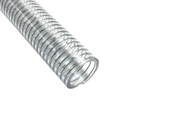
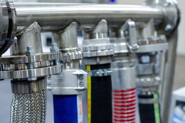
What is Pressure Drop in Hydraulic Systems banner

What is Pressure Drop in Hydraulic Systems?

Pressure drop refers to the reduction in pressure that occurs as hydraulic fluid flows through the components or piping of a hydraulic system. It represents the energy lost due to friction and other resistive forces encountered by the fluid during flow. Pressure drop is a natural phenomenon in any hydraulic system, as the fluid has to overcome internal friction within pipes, hoses, and fittings, as well as the turbulence caused by various components.

Causes of Pressure Drop in Hydraulic Systems

Frictional Resistance

Frictional resistance is one of the most common causes of pressure drop in hydraulic systems. As hydraulic fluid moves through the system’s pipes, hoses, and fittings, it encounters resistance from the internal surfaces of the system components. This resistance occurs because of the friction between the fluid and the walls of the pipes, hoses, or fittings.

Impact of Friction: The longer the pipe or hose and the rougher the internal surface, the greater the friction, and thus the more significant the energy losses. Friction reduces the fluid’s velocity and, consequently, the system’s efficiency, leading to a reduction in pressure. Smooth, well-maintained pipes will reduce frictional losses compared to rough, corroded, or contaminated pipes.

Factors Affecting Friction:

Pipe Length: Longer pipes provide more surface area for friction, increasing the pressure drop.

Pipe Diameter: Smaller diameter pipes increase friction, causing a larger pressure drop.

FluidViscosity: Thicker (more viscous) fluids experience higher frictional resistance compared to thinner (less viscous) fluids, leading to higher pressure drops.

Local Resistance

Local resistance occurs when the hydraulic fluid is forced to change direction or speed. This can happen at points where the fluid flow is disrupted, such as in bends, fittings, valves, or any other changes in the pipeline layout. These disruptions create areas of turbulence or vortices in the fluid, which increases the resistance to flow and causes additional pressure drop.

Turbulent Flow: When the fluid experiences changes in direction or speed, especially in sudden bends or sharp turns, the flow becomes turbulent. Turbulent flow significantly increases resistance compared to laminar (smooth) flow. The energy lost during turbulence contributes to the overall pressure drop.

Impact of Local Resistance:

Flow Direction Changes: Sudden changes in direction, such as sharp bends, elbows, or tees, lead to local turbulence, which increases pressure loss.

Flow Velocity: High-speed fluid flowing through a restrictive section of the system, like a narrowing pipe or valve, leads to increased local resistance and higher pressure drop.

Elbows and Connectors

Elbows, tees, reducers, and other fittings are necessary for the physical layout of hydraulic systems. However, they introduce local resistances that cause pressure drops. The more complex the system with numerous elbows and connectors, the higher the cumulative pressure drop.

How Elbows and Connectors Affect Flow: When the fluid is forced to navigate around elbows or through tees, its flow path becomes obstructed, which increases resistance. These components cause a significant amount of turbulence and friction, leading to a greater energy loss. The larger the angle of the bend or the more restrictive the fitting, the higher the pressure drop.

Minimizing Pressure Drop from Fittings:

Use Larger Radius Elbows: Fittings with larger radii result in smoother transitions for the fluid and lower resistance.

Minimize the Number of Connectors: Minimizing the number of bends, tees, and elbows in a hydraulic circuit will reduce the total pressure drop.

Valve and Control Elements

Valves, filters, and other control elements play a significant role in regulating the flow and pressure of the hydraulic system. However, they can also introduce significant pressure drops, especially if they are improperly sized, installed, or maintained.

Valve Restrictions: A partially closed valve increases the resistance to fluid flow, significantly raising the pressure drop. Even valves that are fully open can cause pressure losses if their design is inadequate for the system’s flow rate. For example, globe valves or throttling valves can cause substantial pressure drops when controlling high-flow conditions.

Clogged Filters: Filters serve to remove contaminants from the hydraulic fluid, but over time, they can become clogged with debris, dirt, or other particulate matter. A clogged filter increases the resistance to fluid flow, causing a noticeable pressure drop. It’s important to regularly inspect and replace filters to avoid excessive pressure loss.

Impact of Control Elements:

Pressure Relief Valves: These are used to maintain system pressure within safe operating limits, but if malfunctioning, they can result in additional pressure losses.

Flow Control Valves: These regulate the flow rate of the fluid in the system, and improper calibration or partial obstruction can create high pressure drops.

Impacts of Pressure Drop on Hydraulic Systems:

Reduced Efficiency

Pressure drop directly results in energy loss within the hydraulic system. As the hydraulic fluid moves through pipes, hoses, and components, the energy required to overcome friction and turbulence is dissipated, primarily in the form of heat. This energy loss reduces the overall efficiency of the system and affects its performance.

Energy Consumption: To compensate for the pressure drop and maintain the desired flow rate, the hydraulic pump must work harder, consuming more energy. This increases the load on the pump, leading to higher operational costs. Over time, the pump may experience increased wear, reducing its lifespan and requiring more frequent maintenance or replacement.

Operational Costs: In industrial systems, significant pressure drops may necessitate the use of larger, more powerful pumps or motors, leading to further increases in energy consumption. This ultimately raises operational costs and contributes to inefficiencies in the system’s overall operation.
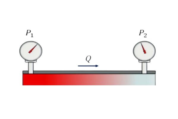
Pressure Drop Systems

Decreased Performance

A significant pressure drop can severely affect the performance of the hydraulic system, particularly in systems that rely on actuators, such as hydraulic cylinders or motors.

Inadequate Force or Speed: The pressure within the system is directly tied to the force and speed generated by hydraulic actuators. If the pressure drops too much, the system may fail to generate the necessary force or speed, which results in poor performance. This could cause slower operation, reduced cycle times, and difficulty achieving the desired motion or precision, especially in tasks that require fine control.

Slower Response Times: In systems where rapid response times are crucial (e.g., in robotics, precision manufacturing, or heavy machinery), a high pressure drop can lead to slower reaction times. This can cause delays in system performance, reduce overall productivity, and compromise the system’s ability to handle time-sensitive tasks efficiently.

Increased Wear and Tear

When the system experiences significant pressure drops, it indicates that fluid is flowing under non-ideal conditions, which puts additional strain on various components like pumps, valves, and fittings.

Strain on Components: As the system works harder to compensate for the loss of pressure, hydraulic components like pumps, valves, seals, and motors are subjected to increased wear and tear. Over time, this strain can lead to premature component failure, requiring more frequent repairs or replacements, increasing maintenance costs, and reducing the overall reliability of the system.

Reduced Lifespan of Components: Prolonged exposure to higher stresses due to pressure drop can shorten the lifespan of critical components. For instance, pumps might suffer from excessive heat generation or cavitation, and seals or valves may wear out more quickly, leading to leaks or failures.

System Overheating

Energy lost as friction and turbulence in the system is typically dissipated as heat. This increase in temperature can cause significant issues within the hydraulic system.

Hydraulic Fluid Degradation: Higher temperatures can accelerate the breakdown of the hydraulic fluid, reducing its effectiveness as a lubricant and coolant. As the fluid degrades, its viscosity changes, which can further exacerbate pressure drops and increase friction in the system. This creates a vicious cycle that leads to even greater energy losses.

Component Damage: Overheating can also cause damage to other system components, such as seals, hoses, and even the pump. Rubber seals may become brittle, and the oil may lose its ability to provide proper lubrication, leading to faster wear and the potential for leakage. If the system operates in a consistently high-temperature range, it may also lead to failure of critical components, resulting in costly repairs or even system shutdowns.

Potential System Failure

Excessive pressure drops can lead to system failure, particularly if the drop exceeds certain operational limits or if the system is not designed to cope with such variations.

Inconsistent Performance: If pressure drops are not addressed, the hydraulic components may operate outside their intended pressure range. This inconsistency can lead to malfunctioning actuators, slower cycle times, or an inability to perform critical tasks. In some cases, the hydraulic system may be unable to maintain the required pressure, causing an immediate failure.

Unplanned Downtime and Repairs: If pressure drops become severe, they may trigger cascading issues within the system. For example, a valve that is struggling to maintain pressure may cause other components to overheat or operate inefficiently. This could lead to unscheduled downtime for repairs, further driving up operational costs and decreasing system availability.

Managing Pressure Drop in Hydraulic Systems

To minimize the impact of pressure drop and ensure optimal performance in a hydraulic system, several key strategies and best practices should be implemented:

Use Properly Sized Piping and Hoses

Ensure that the pipes and hoses are appropriately sized to match the system’s requirements, including flow rate and pressure. Oversized or undersized piping can lead to unnecessary pressure losses. Correct sizing allows the fluid to flow smoothly, reducing the resistance and minimizing pressure drop.

Importance of Proper Sizing: Properly sized piping reduces friction losses and helps maintain consistent flow and pressure. It also ensures that the system operates efficiently without unnecessary strain on the pump or other components.

Minimize Bends and Connections

Each bend, elbow, or connection in the hydraulic system adds resistance to the fluid flow, contributing to additional pressure drop. By minimizing the number of bends and connections in the piping layout, the fluid can flow more smoothly, reducing turbulence and friction.

Optimizing Pipe Layout: Where possible, design the system with fewer turns or use straight pipe sections. Also, choose smooth-flowing fittings and connectors to reduce local resistances at junctions.
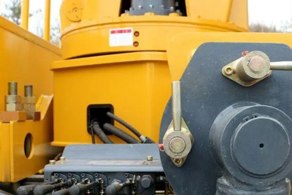
Pressure Drop in Hydraulic Systems

Regularly Clean or Replace Filters

Filters are essential for maintaining the quality of hydraulic fluid and preventing contaminants from entering the system. However, if filters become clogged, they can cause significant pressure drop, restricting fluid flow and reducing system efficiency.

Preventing Blockages: Regularly clean or replace filters to prevent clogging and ensure the fluid can flow freely without added resistance. This will also help maintain the health of the system’s components by preventing damage from contaminants.

Ensure Correct Valve Sizing, Calibration, and Maintenance

Valves play a critical role in regulating fluid flow and pressure in the system. Improperly sized, miscalibrated, or poorly maintained valves can create excessive resistance, leading to pressure drops.

Valve Sizing and Calibration: Ensure that valves are properly sized for the flow requirements of the system and are calibrated to function within their specified pressure range. Regular maintenance and checks should be performed to avoid leaks or blockages that could further impede the flow.

Opt for High-Quality Components with Smooth Internal Surfaces

Using high-quality components with smooth internal surfaces, such as hoses, pipes, and fittings, can significantly reduce friction. Rough or damaged internal surfaces increase resistance, leading to higher pressure drops.

Material Selection: Choose components that are made from materials with low friction coefficients and ensure that the internal surfaces are free from corrosion, roughness, or wear that can disrupt fluid flow.

Use Proper Fluid Viscosity and Keep the Fluid Clean

The viscosity of the hydraulic fluid directly affects the pressure drop. Thicker fluids have higher resistance to flow, causing greater pressure drops. Additionally, contaminants in the fluid, such as dirt or water, can also increase resistance.

Maintaining Fluid Quality: Use the correct fluid viscosity for the operating temperature and conditions. Regularly check and change the hydraulic fluid as needed, and ensure that the fluid is free of contaminants. A clean, appropriately viscous fluid will flow more easily, reducing the overall pressure drop.

Conclusion

Pressure drop results from energy losses due to friction, turbulence, and resistances in various system components, which can lead to higher energy consumption, decreased performance, and increased wear on parts. By implementing effective strategies such as using properly sized piping and hoses, minimizing bends and connections, maintaining clean filters, and ensuring valves and components are appropriately calibrated, the negative impacts of pressure drop can be minimized.


FAQ

What causes pressure drop in hydraulic systems?

Pressure drop is caused by friction, turbulence, and resistance from components like pipes, hoses, valves, and fittings. These factors reduce fluid flow and lead to energy loss.

How does pressure drop affect hydraulic system performance?

Pressure drop can reduce the force and speed of hydraulic actuators, leading to slower operation, less precision, and decreased system efficiency.

How can pressure drop be minimized in hydraulic systems?

To minimize pressure drop, ensure proper sizing of piping and hoses, reduce bends and connections, maintain clean filters, and use high-quality components with smooth internal surfaces.

Why is regular maintenance important for managing pressure drop?

Regular maintenance helps ensure filters are clean, valves are properly calibrated, and components are in good condition, all of which help reduce resistance and prevent excessive pressure drop.

What is the role of fluid viscosity in pressure drop?

Fluid viscosity affects the amount of friction in the system. Using the correct viscosity ensures that the fluid flows smoothly, reducing resistance and minimizing pressure drop.

How does pressure drop increase operational costs?

A high pressure drop forces the hydraulic pump to work harder, consuming more energy. This leads to higher operational costs and can also cause additional wear on the pump, reducing its lifespan.

Hydraulic Hose and Tube Layout banner

Hydraulic Hose and Tube Layout: Correct vs Incorrect Approaches

In hydraulic systems, the correct installation of hoses and tubes is paramount for ensuring optimal performance, safety, and longevity. Most hydraulic hose failures arise from improper assembly or installation, such as twisting, insufficient slack, or incorrect bending, which can drastically reduce the hose’s lifespan and cause catastrophic system malfunctions.

Basics of Hydraulic Pipeline Layout

In any hydraulic system, the layout of hoses and tubes is crucial to ensuring both the functionality and longevity of the system. Hydraulic pipelines can be categorized into two main types of layouts: fixed and flexible. Each serves a different purpose within the system, depending on the specific requirements of the installation and operational conditions.

Fixed Layouts: Use of Steel Pipes for Stationary Sections

Steel pipes are the ideal choice for stationary or rigid sections of a hydraulic system. These sections typically involve areas where the pipeline does not experience significant movement, bending, or vibration. Steel pipes offer several advantages in these applications:

Durability and Strength: Steel pipes are highly durable, providing excellent resistance to high-pressure environments, corrosion, and mechanical stresses.

Permanent Installations: Steel pipes are commonly used in parts of the system where the layout is fixed and does not need to change over time, such as in large industrial machinery or fixed installations.

Reduced Risk of Leakage: With secure, welded or threaded connections, steel pipes are less prone to leaks compared to flexible hoses in stationary sections.

Fixed layouts using steel pipes are often preferred in situations where the system is not subject to movement or vibration, and where the installation needs to withstand high temperatures or harsh environments.

Flexible Layouts: Use of Hoses for Dynamic Parts

On the other hand, flexible hydraulic hoses are typically used in parts of the system that are dynamic or subject to movement. Hoses are the best option for connecting components that need to move or adjust in position, such as actuators, rotating machinery, or parts that vibrate under normal operation. The main advantages of using hydraulic hoses for flexible layouts include:

Flexibility and Mobility: Hydraulic hoses can bend, twist, and move with the system, making them ideal for connections in dynamic parts where rigid pipes would fail or cause stress.

Vibration Absorption: Hoses can absorb vibrations and pressure fluctuations, reducing the risk of damage to the system and extending its lifespan.

Ease of Installation and Maintenance: Hoses can be easily routed around obstacles, simplifying installation and offering more flexibility for repairs and maintenance.

However, it’s essential to follow proper installation practices to prevent common issues such as excessive twisting, bending beyond the recommended radius, or chafing against surrounding objects.

Cost and Appearance Considerations

Choosing between steel pipes and hydraulic hoses often involves a balance of several factors, including cost, space limitations, appearance, and the system’s operational needs. In some cases, the difference in cost between hoses and steel tubes may be marginal, but the decision can still be influenced by factors such as:

Vibration Sensitivity: Systems that are subjected to frequent vibration or movement often benefit from hoses, as they are better equipped to handle dynamic stresses without compromising the integrity of the system.

Aesthetic Considerations: In some applications, especially in visible areas or consumer-facing equipment, hoses may be preferred for their more streamlined and flexible appearance. Hoses can be routed around obstacles without the need for bulky pipe fittings.

Installation Complexity: Although steel pipes are durable, they can be more challenging and expensive to install, requiring more labor-intensive processes such as welding or threading. Hoses, in contrast, are typically quicker and simpler to install and may be chosen to reduce labor costs.

Hydraulic Hose Installation Standards

Proper installation of hydraulic hoses is essential to ensure the longevity and performance of the entire hydraulic system. The following standards focus on specific aspects of hydraulic hose installation, including preventing twisting, ensuring adequate allowance for expansion, avoiding damaging clamps, and adhering to bend radius requirements.

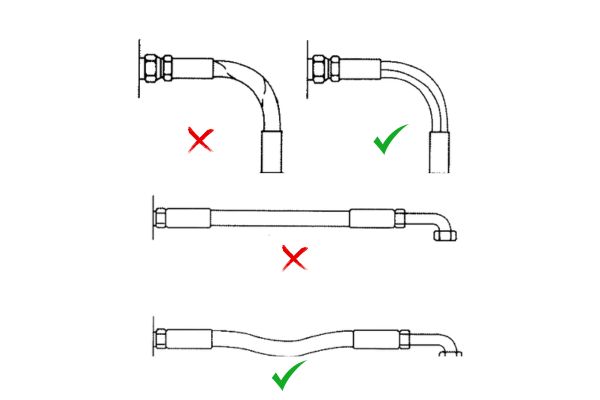
Hydraulic Hose Layout wrong and right

Twisting

Twisting is one of the most common installation errors that significantly impacts the lifespan of hydraulic hoses. When a hose is twisted, even slightly, it introduces stress on the internal structure, leading to premature wear and potential failure. The negative effects of twisting include:

Reduced Flexibility: Twisting restricts the hose’s ability to flex and expand, leading to cracks or ruptures over time.

Increased Risk of Leaks: Twisted hoses are more prone to loosening at connection points, resulting in leaks.

Test Data: Research has shown that a mere 7° twist in a hydraulic hose can reduce its service life by up to 80%. This underscores the importance of avoiding any form of twisting during installation. To prevent this, hoses should always be routed in a manner that allows for free movement without any twisting forces.

Allowance for Straight Tubes

When installing straight sections of hydraulic hose, it is important to leave extra length to accommodate pressure fluctuations and hose expansion. Hydraulic hoses naturally expand and contract under pressure, and without sufficient slack, the hose could become overstretched, leading to damage or failure.

Why Allowance is Important: Pressure variations and thermal changes cause hoses to expand or contract. Without adequate slack, the hose may become too taut, which can cause excessive wear or even rupture.

Recommended Allowance: For optimal performance, it is recommended to leave a 3%–5% allowance in the length of the hose, ensuring that the hose can expand and contract without restriction.

Avoiding Clamps on Curved Sections

Clamps are used to secure hoses and prevent them from moving excessively, but placing clamps on curved sections of a hose can lead to serious issues. When a hose bends, there is an unequal distribution of pressure inside the hose, with more pressure on the outer bend and less pressure on the inner bend.

Potential Issues:

Pressure Imbalance: When a clamp is placed on a bend, it can restrict the hose’s natural movement, potentially causing it to crack, wear prematurely, or even rupture at the clamp location.

Inability to Flex: Clamps can prevent the hose from flexing freely at its most vulnerable points (the bend), leading to increased friction and wear.

To avoid these issues, clamps should not be placed on curved sections. Instead, allow the hose to move freely in the bend, reducing stress and preventing long-term damage.

Bend Radius Requirements

Every hydraulic hose has a minimum bend radius, which is the smallest radius a hose can be bent without risking damage to the internal structure or the outer reinforcement (such as steel braids or spiral wound wires).

Impact of Tight Bend Radius: Bending a hose too tightly increases the risk of damaging the external reinforcement, which can lead to hose failure. A tight bend radius can also lead to kinking, which severely compromises the hose’s flexibility and ability to carry fluid.

Recommended Bend Radius: The bend radius for each hose is typically specified by the manufacturer and is usually measured in terms of the hose’s diameter. It is critical to adhere to this specified bend radius to ensure that the hose maintains its durability and performance over time.

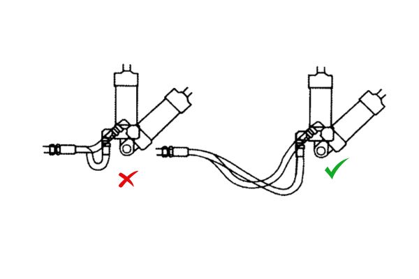
Movement Adaptability

Hydraulic hoses need to be flexible to accommodate movement within the system. Components such as actuators, rotating machinery, and machinery in motion all require hoses that can move with them without being stressed or damaged.

Why Length Matters: Hose length should be chosen with care to ensure adequate slack is available for movement. A hose that is too short may be stretched or put under excessive stress, leading to premature failure.

Preventing Friction: Movement flexibility also helps prevent hoses from rubbing against surrounding objects, which can cause external abrasion and damage. Routing hoses in a way that prevents friction with sharp edges or other components is critical.

movable Hydraulic Hose Layout

Heat Insulation and Friction Protection

Hydraulic hoses are often exposed to extreme temperatures, as well as friction from constant movement. To prevent damage from these environmental factors, protective measures should be taken:

Heat Insulation: When hoses are exposed to high temperatures, the material can degrade faster. Protective covers or insulation can be used to reduce exposure to heat and prevent hose material from breaking down.

Friction Protection: Hoses that are subject to constant movement or those routed near sharp edges or abrasive surfaces need additional protection. Using covers, sleeves, or clamps can help prevent the hose from rubbing against other components, significantly reducing wear and tear.

By following these installation standards, hydraulic hoses can be protected from common issues such as twisting, excessive pressure, and friction, ultimately ensuring the longevity and reliability of the hydraulic system.

Hydraulic Tube Installation Standards

Proper installation of hydraulic tubes is critical for system efficiency, safety, and longevity. Hydraulic tubes, unlike hoses, are typically used for stationary connections, and their installation standards focus on ensuring durability, reducing energy loss, and preventing damage from thermal expansion. The following guidelines provide key standards for installing hydraulic tubes, covering tube length, diameter, support, and routing.

Tube Length and Diameter

When installing hydraulic tubes, it is important to avoid using excessively long tubes, as this can lead to energy loss and other performance issues.

Avoiding Overly Long Tubes: Long tubes can increase the system’s resistance to fluid flow, leading to higher energy consumption. The longer the tube, the more friction the fluid experiences as it moves through, resulting in a loss of efficiency and potentially lower overall system performance.

Diameter Considerations: The tube diameter should be chosen carefully to match the flow rate and pressure requirements of the system. Too small a diameter can increase resistance and lead to higher pressure drops, while too large a diameter can create unnecessary space for fluid to flow, again leading to energy loss.

The length and diameter of hydraulic tubes should always be optimized for the system’s specific needs to ensure energy efficiency and smooth fluid flow.

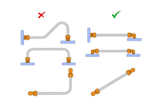
Hydraulic Tube Layout

Connection Between Fixed Points

When connecting hydraulic tubes between fixed points, it’s important to ensure that the tubes are not subjected to tight pulls or excessive tension. Tight pulls can place undue stress on the tubes, leading to failure or damage.

Avoiding Tight Pulls: Tubes should be routed in a way that allows for natural movement without being overstretched. Tight pulls can lead to permanent deformation, causing the tubes to lose their shape and strength over time.

Flexibility for Easy Installation and Removal: It’s essential to allow for some flexibility between fixed points, particularly in areas where tubes may need to be removed for maintenance. This ensures that the system can be easily serviced and that tubes are not damaged during installation or removal.

Thermal Expansion and Contraction: Tubes must be installed with sufficient slack to accommodate thermal expansion and contraction. As the fluid temperature fluctuates, the tube material can expand or contract, placing additional stress on the system if not allowed to move freely. Allowing enough slack prevents these stresses from causing tube damage or premature wear.

Minimum Bend Radius

Each hydraulic tube has a minimum bend radius, which is the smallest radius the tube can be bent without causing damage to the tube’s structure or compromising its performance.

Minimum Bend Radius: The minimum bend radius is generally specified as 2.5 times the tube’s diameter. This ensures that the tube retains its structural integrity during installation and operation. Bending a tube tighter than the minimum radius can lead to deformation, kinking, or rupture.

Ensuring Adequate Straight Sections: At the ends of the tube, it’s important to provide a straight section to facilitate secure fittings. The straight sections should be at least twice the length of the fitting nut to ensure that the tube can be properly connected to the fittings without stressing the tube or creating leaks.

Maintaining the minimum bend radius and providing straight sections at the tube ends are essential for the safe and effective operation of the hydraulic system.

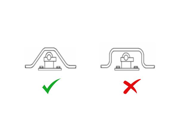
Tube Support with Clamps

Support and secure hydraulic tubes using clamps to prevent excessive movement, vibrations, and noise. Properly installed clamps can reduce the risk of damage, extend tube life, and improve the system’s overall performance.

Using Clamps to Support Longer Tubes: Long tubes that are not supported can move under pressure or vibration, leading to wear, rubbing, or even failure at connection points. Clamps help secure the tube in place and reduce the risk of damage.

Reducing Vibrations and Noise: Clamps can also help to reduce vibration and associated noise in the hydraulic system by providing stability to the tube. They ensure that the tube does not move excessively, especially in areas subject to high-frequency vibrations.

Recommended Clamp Distance: The distance between clamps should be sufficient to prevent sagging or excessive movement while allowing for thermal expansion and contraction. Typically, the clamp spacing should be between 1.5 to 2 times the diameter of the tube. Clamp installation should also allow for easy removal and maintenance, avoiding over-tightening that could damage the tube.

Avoiding Excessive 90° Bends

Sharp bends, especially 90° bends, should be avoided in hydraulic tube layouts due to the negative impact on fluid flow and system efficiency.

Impact on FluidPressure Drop: A 90° bend causes a significant pressure drop in the fluid, as the flow is sharply redirected. This creates turbulence and increases the energy required to move the fluid through the system.

Prefer Two 45° Bends Instead of One 90° Bend: Instead of using a single 90° bend, it is preferable to use two 45° bends. This allows for a smoother transition of fluid, reducing turbulence and minimizing pressure drop, ultimately improving system efficiency.

Avoiding Excessive 90° Bends

Routing and Maintenance Access

Proper routing of hydraulic tubes is essential for ease of maintenance, troubleshooting, and long-term system health.

Routing Away from Frequently Serviced Areas: When laying out hydraulic tubes, it is important to avoid routing them through areas that require frequent maintenance or are subject to constant disruption. This helps prevent accidental damage and makes future servicing more accessible.

Neat and Organized Layout: Tubes should be neatly routed in a way that allows easy access for inspection, troubleshooting, and repair. An organized layout reduces the risk of errors during maintenance, ensures better visibility for system checks, and minimizes potential hazards in the work environment.

Conclusion

The layout and installation of hydraulic hoses and tubes are foundational to ensuring the reliability and longevity of hydraulic systems. Poor installation practices, such as incorrect bending, twisting, or inadequate slack, can lead to system inefficiencies, higher maintenance costs, and increased risk of failure. Properly routed hoses and tubes, when installed according to the best practices, not only enhance the system’s performance but also contribute to its long-term sustainability.


FAQ

Why is it important to avoid twisting hydraulic hoses during installation?

Twisting hydraulic hoses can significantly shorten their lifespan. Even a small twist (as little as 7°) can reduce the hose’s durability by up to 80%, leading to cracks, leaks, or rupture under pressure.

How much allowance should I leave for straight tubes during installation?

It’s recommended to leave an allowance of 3%–5% for straight hydraulic hoses. This extra length accommodates expansion and contraction due to pressure changes, preventing the hose from being overstretched or damaged.

Why shouldn’t I use clamps on curved sections of hydraulic hoses?

Clamps on curved sections can restrict the natural movement of the hose, causing stress and wear at the bend. This can lead to hose failure. It’s best to allow the hose to move freely without clamps in curved areas.

What is the minimum bend radius for hydraulic tubes?

The minimum bend radius for hydraulic tubes is typically 2.5 times the diameter of the tube. Bending tubes tighter than this can damage the tube’s structure and shorten its lifespan.

How do I prevent hydraulic tubes from vibrating or making noise?

To prevent vibrations and noise, use clamps to support longer tubes, especially in areas prone to movement. Properly spaced and securely installed clamps help stabilize the tube and reduce the impact of vibrations.

Can I use a 90° bend for hydraulic tubes?

It’s better to use two 45° bends instead of one 90° bend. A single 90° bend creates a higher pressure drop in the fluid flow, reducing system efficiency. Two 45° bends minimize this pressure loss and maintain optimal fluid flow.

Types of Industrial Hoses and Their Key Uses banner

Types of Industrial Hoses and Their Key Uses

Industrial hoses play a crucial role in a wide range of industries, facilitating the safe and efficient transportation of materials such as chemicals, fuels, water, and air. Key factors such as material compatibility, pressure ratings, flexibility, and temperature resistance are essential in selecting the appropriate hose for each application. With various types available—like flexible hoses, hydraulic hoses, rubber hoses, and PVC hoses—industrial hoses are highly versatile and adapted to meet the unique needs of industries such as manufacturing, construction, mining, and food processing.

What Are Industrial Hoses?

Key Features of Industrial Hoses

Industrial hoses are specially engineered tubes used to transport liquids, gases, and solids in various industrial applications. They are designed to withstand harsh conditions and are constructed from durable materials that offer flexibility, strength, and resistance to pressure, chemicals, and temperature extremes. Key features of industrial hoses include:

Material Composition: Typically made from rubber, PVC, polyurethane, or composite materials to meet specific performance needs.

Reinforcement: Many hoses feature internal reinforcement (e.g., steel, polyester) to enhance strength and prevent collapse under high pressure.

Flexibility: Designed to bend and flex, industrial hoses can adapt to changing system layouts and challenging work environments.

Temperature and Pressure Resistance: They are built to handle varying temperature ranges and pressures, crucial for maintaining safe and effective operation.

Chemical and Abrasion Resistance: Industrial hoses are often resistant to wear, UV damage, and the chemical properties of the fluids they transport.

Common Applications Across Industries

Industrial hoses are essential in numerous industries for a variety of applications. Some of the most common include:

Manufacturing: Used to transport water, air, and lubricants in machines, cooling systems, and production lines.

Construction: Employed to transfer cement, slurry, and water, as well as for hydraulic systems in heavy equipment.

Mining: Used for slurry transportation, dust control, and handling abrasive materials.

Chemical Processing: Designed for transporting chemicals, acids, and solvents safely within processing plants.

Oil & Gas: Transporting crude oil, fuel, and gas in refineries, offshore platforms, and pipelines.

Food and Beverage: Food-grade hoses are used to handle ingredients, liquids, and gases safely, ensuring hygiene and regulatory compliance.

Pharmaceutical: Transporting liquids and powders in controlled environments, ensuring material purity and safety.

Agriculture: Used for irrigation, pesticide spraying, and liquid fertilizer transportation. Each application demands hoses with specific materials and performance capabilities to ensure the smooth operation and safety of processes.

The Different Types of Industrial Hoses

Industrial hoses are essential components across a wide range of industries, including manufacturing, construction, agriculture, and transportation. These hoses are designed to handle specific materials, pressures, and environmental conditions. Each type of industrial hose serves a particular function, with varying characteristics tailored to its specific use.

Flexible Hoses

Flexible hoses are widely regarded as the most versatile type of industrial hose due to their ability to bend and twist without compromising their function. These hoses are typically made from materials like rubber, PVC, or Teflon, and are used in a wide array of industries, from automotive to food processing. They are suitable for carrying liquids, gases, and slurries, and are designed to handle a range of pressures and temperatures.

Flexible hoses can be reinforced with braided stainless steel or textile materials for added durability, and their versatility makes them perfect for applications where space is limited or where hose flexibility is required for dynamic movements.

Pneumatic Hoses

Pneumatic hoses are specialized for the transportation of compressed air and gases. They are primarily used in systems that power pneumatic tools, such as drills, pumps, and actuators, or for air-driven machinery. Pneumatic hoses are made from materials that can withstand high-pressure environments and are often reinforced with synthetic fabrics or braided steel to ensure strength and prevent bursting.

These hoses are designed to resist wear and abrasion while maintaining flexibility for easy routing around equipment. Due to the nature of their function, pneumatic hoses must also be resistant to kinking and tangling to ensure uninterrupted operation in demanding environments.

Fuel Hoses

Fuel hoses are engineered to transport fuels, oils, and other petroleum-based products safely and efficiently. These hoses must be highly resistant to petroleum products, heat, and abrasion, ensuring that they do not degrade over time or leak harmful substances. Typically made from rubber or composite materials, fuel hoses are often reinforced with steel or textile braids to provide the strength needed for high-pressure applications.

Fuel hoses are commonly used in automotive, marine, and aviation applications, and they come in various diameters to accommodate different flow rates and fuel types. Specialized versions are also available for use with biodiesel and other alternative fuels, ensuring compatibility with a wide range of fuels and oils.

Steam Hoses

Steam hoses are designed to handle high-temperature, high-pressure steam. These hoses are typically made from materials that can withstand extreme heat and pressure, such as reinforced rubber or Teflon. They are often used in industries like power generation, food processing, and chemical manufacturing, where steam is used for cleaning, heating, or power production.

The construction of steam hoses includes multiple layers of material, with an inner layer that resists the high temperatures and an outer layer that protects against wear and mechanical damage. Steam hoses must also be durable enough to prevent leaks, which can be hazardous in high-temperature environments.

suction Industrial hose

Suction Hose

Suction hoses are designed to transport liquids or slurries in suction or vacuum applications. These hoses are commonly used in industrial cleaning, water transfer, and dredging applications, where the hose is required to suction fluids from a source and transport them to a different location. Suction hoses are typically constructed from flexible, durable materials like PVC, rubber, or polyurethane, and are reinforced with spiraled steel or textile braids for added strength.

Suction hoses are designed to withstand the negative pressure generated during suction, ensuring they maintain their structural integrity under challenging conditions. They are available in various sizes and configurations, making them ideal for applications requiring flexibility and durability.

Dredging Hose

Dredging hoses are a specialized type of industrial hose used for the transport of heavy sediments, mud, and other materials during dredging operations. These hoses are built to handle extreme pressure and abrasive materials, often used in applications such as mining, harbor dredging, and underwater construction. The design of dredging hoses includes thick, reinforced walls to protect against wear and tear from abrasive particles.

These hoses are typically constructed from high-quality rubber, with added reinforcements like steel or textile braiding to provide resistance to internal and external pressures. Dredging hoses must also be highly flexible to navigate the dynamic movements involved in dredging operations.

Choosing the Right Hose for Your Application

Hose Selection Guide: What to Consider

When selecting the right industrial hose for a particular application, several key factors should be considered to ensure performance, safety, and longevity:

Material Compatibility: Choose a hose material that is compatible with the fluid or gas being transported. For example, chemical-resistant hoses are needed for aggressive chemicals, while food-grade hoses are required in the food industry.

Environmental Conditions: Consider factors such as exposure to UV rays, extreme temperatures, moisture, and abrasion. Select a hose that can withstand these conditions without degrading.

Flexibility and Bend Radius: Depending on the space and layout of the installation, you may need a hose with high flexibility or one that can handle tight bends without kinking.

Durability and Wear Resistance: Hoses that will be exposed to abrasive materials or harsh environments need to be durable and resistant to wear and tear.

Pressure and Flow Requirements: The hose must meet the specific pressure and flow requirements of your system to function effectively.

Assessing Pressure Ratings and Temperature Resistance

Each industrial hose has a specific pressure rating that indicates the maximum pressure it can safely handle during operation. Similarly, temperature resistance is a crucial factor, as hoses are often exposed to extreme temperatures, both hot and cold.

Pressure Ratings: Choose a hose with a pressure rating that exceeds the maximum pressure your system will generate. Ensure the hose can handle pressure spikes and sudden increases.

Temperature Resistance: Ensure the hose can withstand the temperatures it will be exposed to without compromising the material integrity. Some hoses are specifically designed to handle high temperatures, such as steam hoses, while others are built for cryogenic conditions.

Pressure and Temperature Safety Margins: It’s important to select hoses with safety margins to account for unexpected conditions and fluctuations in pressure or temperature.

Understanding Hose Size and Compatibility

Selecting the right hose size is crucial for optimal performance. The hose diameter, along with the inside and outside diameters, determines the flow rate and pressure capabilities of the system.

Inner Diameter (ID): The inner diameter of the hose should be large enough to accommodate the volume of material being transported without causing excess friction or pressure drops.

Outer Diameter (OD): The outer diameter is important for fitting compatibility. Ensure that the hose fits securely into the connectors, flanges, and fittings in your system.

Length of the Hose: The hose length must be suitable for the distance the fluid or gas must travel, with enough slack for flexibility and movement.

Fitting Compatibility: Ensure that the hose fittings match the hose size and type, such as BSP, NPT, or SAE, for a secure, leak-proof connection.

Industrial Hoses Types

How to Choose Between Reinforced and Non-Reinforced Hoses

Reinforced hoses have internal layers, such as steel wire or textile fibers, that increase the hose’s strength and ability to withstand higher pressures and rough handling. Non-reinforced hoses, while more flexible, are suitable for low-pressure and less demanding applications.

Reinforced Hoses: Ideal for high-pressure environments or where the hose is subjected to extreme physical stress. Reinforced hoses are more rigid but offer superior durability and resistance to crushing.

Non-Reinforced Hoses: Best for low-pressure applications and where flexibility and ease of handling are the priority. These hoses are typically lighter and more flexible but may collapse under high-pressure conditions.

Application-Based Choice: Consider whether your application demands high pressure, constant movement, or resistance to crushing or abrasion to determine if reinforcement is necessary.

Custom Hoses: Tailoring Solutions for Unique Needs

When to Consider Custom Hoses for Your Project

Custom hoses are essential when standard hoses do not meet the specific requirements of an application. There are several scenarios where opting for custom hoses can be the best solution:

Unusual Materials or Fluids: When you need to transport chemicals, fuels, or other substances that require a hose made from a specific material (such as chemical-resistant rubber or PTFE).

Non-Standard Sizes or Lengths: If the application requires hoses with unique diameters, lengths, or connections that aren’t readily available in the market.

Specialized Environments: In industries with extreme conditions (high pressures, high temperatures, exposure to chemicals, etc.), custom hoses can be designed to meet these challenges.

Complex Applications: For projects that involve intricate setups where standard hoses simply won’t fit or provide the necessary performance. This includes applications in aerospace, automotive, or custom machinery.

High Durability or Specific Performance Needs: When you need a hose that can endure heavy-duty use, custom hoses can be designed for enhanced abrasion resistance, pressure tolerance, and longevity.

By working with manufacturers to create a custom hose, you ensure that the hose is perfectly suited to your system’s needs, improving safety, efficiency, and performance.

How Custom Hoses Are Made

The process of making custom hoses involves several key steps to ensure that the hose meets the exact specifications required for the application:

Initial Consultation and Design: This involves discussing the specific requirements of the application, including fluid or gas types, pressure ratings, temperature ranges, and environmental conditions. Based on this, the hose design is tailored to match those needs.

Material Selection: The right materials are chosen based on factors such as chemical compatibility, flexibility, strength, and temperature resistance. Materials like rubber, Teflon, PVC, or stainless steel might be selected depending on the hose’s function.

Hose Construction: The hose is built layer by layer, with specific reinforcements (such as braided steel or textile) added to enhance strength and durability. Specialized coatings or linings may also be applied for added protection.

Customization of Fittings and Connections: Custom fittings and connectors are designed to ensure that the hose is compatible with the equipment or system it will be attached to. These fittings are tailored to ensure leak-proof seals and optimal flow performance.

Testing and Quality Control: Custom hoses undergo rigorous testing to ensure they meet the required standards for pressure, temperature, and performance. The hoses are also tested for flexibility, durability, and any other specific criteria outlined during the design phase.

This detailed and customized process ensures that every hose created meets the precise needs of the application.

Benefits of Using Custom Hoses in Specialized Applications

Custom hoses offer several advantages over off-the-shelf options, particularly in specialized applications that demand high performance, precision, and reliability:

Perfect Fit for Specific Requirements: Custom hoses are designed to meet the exact specifications of your application, from size and material to pressure rating and flexibility. This ensures optimal performance and safety.

Enhanced Durability: Custom hoses can be built with more durable materials and reinforcements to withstand harsh conditions, such as high pressure, extreme temperatures, or exposure to abrasive substances. This extends the hose’s lifespan and reduces the likelihood of premature failure.

Improved Safety: By tailoring the hose to your system’s unique demands, custom hoses help minimize the risk of accidents, leaks, and hose failure. A hose that perfectly fits your system is less likely to experience issues that could lead to downtime or safety hazards.

Conclusion

Choosing the right industrial hose is critical to ensuring the safety, efficiency, and longevity of your operations. Various types of hose are designed to meet specific needs, and each plays a vital role in maintaining smooth, safe industrial processes. If you need any industrial hose, contact us and Topa can help!


FAQ

What are industrial hoses used for?

Industrial hoses are used to transport liquids, gases, chemicals, and powders in a variety of industries, including manufacturing, automotive, construction, and food processing.

How do I choose the right industrial hose?

Consider factors such as the material being transported, the pressure and temperature requirements, hose flexibility, and environmental conditions when selecting the right hose for your application.

What is the difference between flexible and reinforced hoses?

Flexible hoses are designed to bend and adapt to tight spaces, while reinforced hoses have additional layers for strength, making them suitable for high-pressure or heavy-duty applications.

Can I use any hose for fuel transfer?

No, fuel hoses are specifically designed to handle petroleum-based products, ensuring they resist degradation and withstand the pressures and temperatures typical of fuel systems.

How often should industrial hoses be replaced?

Hoses should be replaced when they show signs of wear, such as cracks, leaks, or reduced performance. Regular inspection and maintenance help determine when replacement is necessary.

Are custom hoses available for specific applications?

Yes, custom hoses can be made to meet unique requirements such as size, material, pressure ratings, and environmental conditions, providing tailored solutions for specialized needs.

Contact Topa

Save 30% on maintenance costs with our easy-install hydraulic fittings. Contact Now!