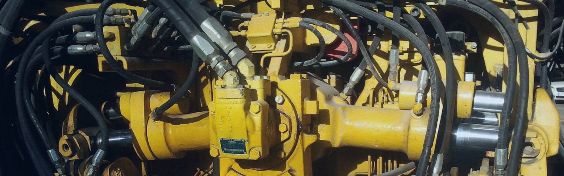
In the complex world of fluid power systems, hydraulic adapters serve as critical components that enable the connection of hoses, tubes, and various system elements. Despite their seemingly simple function, the selection of appropriate adapters requires a nuanced understanding of thread types, sizing conventions, and coding systems. Incorrect adapter selection can lead to catastrophic system failures, fluid leaks, pressure losses, and safety hazards.
Fundamentals of Hydraulic Adapters
Definition and Primary Functions
Hydraulic adapters are precision-engineered components designed to connect different elements within a hydraulic system. Unlike fittings that typically connect hoses to components, adapters primarily serve to:
- Connect components with different thread types or sizes
- Change the direction of fluid flow
- Branch fluid paths (as in tee or cross configurations)
- Extend connection points
- Convert between different thread standards
The primary function of an adapter is to maintain system integrity by providing leak-free connections capable of withstanding the system’s operating pressure while ensuring unimpeded fluid flow.
Key Components
A typical hydraulic adapter consists of several key elements:
- Male Threads (External): Protrude outward and connect to female threads. Often referred to as “male ends” or “male connections.”
- Female Threads (Internal): Recessed within the adapter body and accept male threads. Commonly called “female ends” or “female connections.”
- Sealing Surfaces: Depending on the thread type, these may include:
- Hex Body: The central portion featuring flats for wrench engagement during installation.
- Flow Passage: The internal channel that allows fluid to pass through the adapter.
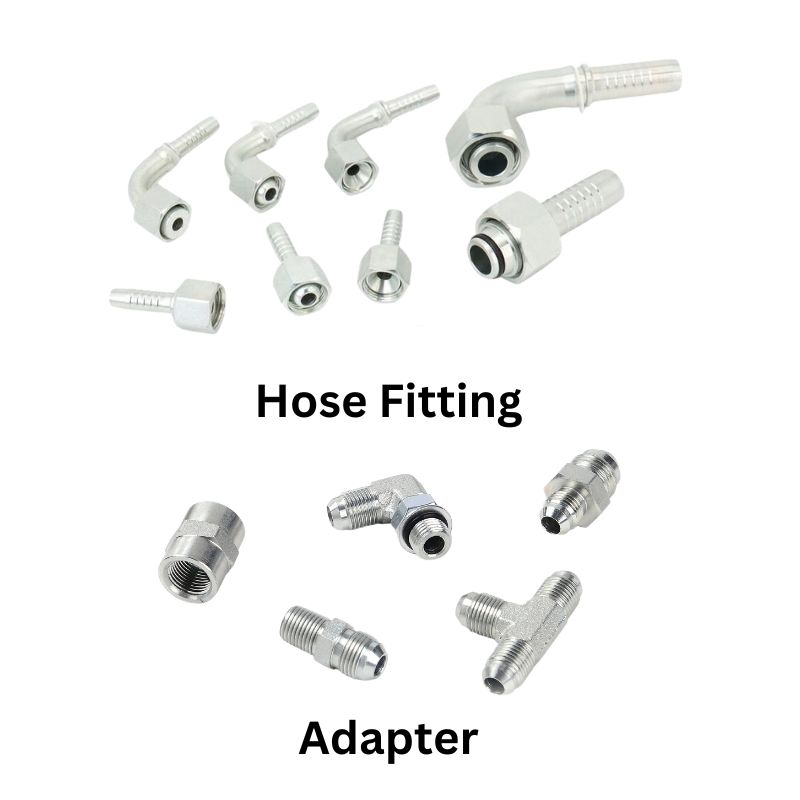
Distinction from Hose Fittings
While adapters and fittings are sometimes used interchangeably in conversation, they serve distinct purposes:
Adapters typically feature threads on both ends and connect components with different thread types or sizes.
Hose Fittings generally have one threaded end and one end designed to attach to a hose (often through crimping, swaging, or clamping).
This article focuses primarily on adapters with threaded connections on both ends, sometimes referred to as “transition fittings” or “conversion adapters.”
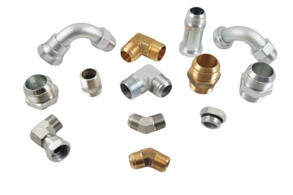
Common Materials and Pressure Ratings
Hydraulic adapters are manufactured from various materials to suit different applications:
- Carbon Steel: Most common for standard industrial applications, typically zinc-plated for corrosion resistance.
- Stainless Steel: Used in corrosive environments, food processing, marine applications, and where chemical compatibility is required.
- Brass: Common in lower-pressure applications, particularly where non-sparking properties are needed.
- Aluminum: Used in weight-sensitive applications like aerospace and mobile equipment.
Pressure ratings vary significantly based on material, size, and design, but typically range from:
- Low pressure: Up to 1,000 PSI (69 bar)
- Medium pressure: 1,000-3,000 PSI (69-207 bar)
- High pressure: 3,000-6,000 PSI (207-414 bar)
- Ultra-high pressure: Above 6,000 PSI (414+ bar)
Always consult manufacturer specifications for precise pressure ratings for specific adapters.
Thread Types and Standards
A. BSP (British Standard Pipe)
History and Development
The British Standard Pipe (BSP) thread was developed in the 1840s by Sir Joseph Whitworth and became one of the first standardized thread systems worldwide. It was adopted as a standard for pipe connections in the British Empire and remains prevalent in many Commonwealth countries, Europe, and Asia.
Parallel vs. Tapered Threads
BSP threads come in two primary variants:
BSPP (British Standard Pipe Parallel): Also known as “G” threads, these maintain the same diameter throughout their length. BSPP connections rely on a separate sealing mechanism, such as an O-ring, bonded seal, or metal-to-metal contact with a 30° chamfer.
BSPT (British Standard Pipe Tapered): Also known as “R” threads, these taper at 1:16, meaning the diameter reduces by 1 unit for every 16 units of length. The taper creates an interference fit that forms the seal when properly tightened.
Common Sizes and Identification
BSP sizes are designated in inches, though they don’t directly correspond to the thread’s actual dimensions. Common sizes include:
| Nominal Size | Thread Pitch | Outside Diameter (mm) |
| 1/8″ | 28 TPI | 9.728 |
| 1/4″ | 19 TPI | 13.157 |
| 3/8″ | 19 TPI | 16.662 |
| 1/2″ | 14 TPI | 20.955 |
| 3/4″ | 14 TPI | 26.441 |
| 1″ | 11 TPI | 33.249 |
BSP threads can be identified by:
- The Whitworth thread form with a 55° angle
- Rounded thread crests and roots
- Thread pitch measured in threads per inch (TPI)
- “G” (BSPP) or “R” (BSPT) markings on components
Sealing Methods and Compatibility
BSPP connections typically use one of these sealing methods:
- Bonded seals (washers with a rubber insert)
- O-rings seated against a 30° chamfer
- Dowty washers
- Thread sealant (less common and not recommended for high-pressure applications)
BSPT connections rely on:
- Thread deformation and interference fit
- Thread sealant or PTFE tape to enhance sealing
BSP threads are not directly compatible with other thread standards without appropriate adapters, despite some having similar dimensions to NPT or metric threads.
B. JIC (Joint Industry Council)
Origin and Standardization
The Joint Industry Council (JIC) standard was developed in the United States during the 1950s to create uniformity in industrial hydraulic connections. It was later incorporated into SAE J514 and has become one of the most widely used connection standards in North American hydraulic systems.
37° Flare Sealing Mechanism
The defining characteristic of JIC fittings is the 37° flared sealing surface:
- The male end features a 37° cone that mates with a corresponding 37° flare on the female end.
- The seal is created by metal-to-metal contact between these surfaces when the connection is properly tightened.
- No additional sealing elements (like O-rings or thread sealant) are required.
This design provides excellent vibration resistance and reliability in high-pressure applications.
Size Designations and Thread Specifications
JIC fittings use a dash number system based on 1/16-inch increments:
| Dash Size | Fraction | Thread Size |
| -4 | 1/4″ | 7/16-20 UNF |
| -6 | 3/8″ | 9/16-18 UNF |
| -8 | 1/2″ | 3/4-16 UNF |
| -10 | 5/8″ | 7/8-14 UNF |
| -12 | 3/4″ | 1-1/16-12 UNF |
| -16 | 1″ | 1-5/16-12 UNF |
JIC threads are straight (parallel) Unified National Fine (UNF) threads with a 60° thread angle. The threads themselves do not provide the seal; they only hold the components together while the flared surfaces create the seal.
C. Metric Threads
Light Series vs. Heavy Series
Metric hydraulic connections are divided into two main series:
- Light Series (L): Designated by the letter “C” in adapter codes, these are designed for lower pressure applications and feature thinner walls.
- Heavy Series (S): Designated by the letter “D” in adapter codes, these have thicker walls for higher pressure applications.
The two series are not interchangeable despite sometimes having similar thread dimensions.
DIN Standards and Specifications
Metric hydraulic connections are governed by several DIN (Deutsches Institut für Normung) standards:
- DIN 2353: Compression fittings with cutting rings
- DIN 3852: Threaded connections for fluid power applications
- ISO 8434-1: 24° cone connectors with O-ring
These standards define thread dimensions, sealing methods, and performance requirements.
24° Cone Sealing System
The most common metric hydraulic connection uses a 24° cone sealing system:
- The male fitting has a 24° cone that mates with a corresponding seat in the female connection.
- A cutting ring or ferrule creates two sealing points: one between the ring and the tube, and another between the ring and the fitting body.
- When properly tightened, the cutting ring slightly deforms the tube, creating a permanent connection.
This system provides excellent vibration resistance and reliable sealing in high-pressure applications.
Size Designations and Compatibility Issues
Metric connections are designated by their nominal tube outside diameter in millimeters:
| Metric Size | Approximate Inch Equivalent | Thread Size |
| 6mm | 1/4″ | M10x1 or M12x1.5 |
| 8mm | 5/16″ | M12x1 or M14x1.5 |
| 10mm | 3/8″ | M14x1 or M16x1.5 |
| 12mm | 1/2″ | M16x1 or M18x1.5 |
| 15mm | 5/8″ | M18x1 or M22x1.5 |
| 18mm | 3/4″ | M22x1 or M26x1.5 |
Compatibility issues arise from:
- Different thread pitches for the same nominal size
- Light vs. heavy series differences
- Variations in sealing methods (O-ring vs. cutting ring)
- Different cone angles in some specialized applications
D. Other Common Thread Standards
NPT/NPTF (National Pipe Tapered)
National Pipe Tapered (NPT) threads are widely used in North America:
- Feature a 60° thread angle with flattened peaks and valleys
- Taper at a rate of 1:16 (similar to BSPT)
- Rely on thread deformation for sealing, often enhanced with PTFE tape or liquid sealant
- Sizes are designated in inches (e.g., 1/4″, 1/2″)
NPTF (National Pipe Tapered Fuel) is a variation designed to seal without additional sealant, featuring slightly modified thread crests and roots that create a more effective interference fit.
SAE Straight Thread
SAE straight thread fittings use O-rings for sealing:
- Straight (parallel) threads with a 60° angle
- O-ring compressed against a flat surface or in a gland
- Threads only provide mechanical connection, not sealing
- Common in mobile equipment and automotive applications
- Designated by dash sizes similar to JIC
ORFS (O-Ring Face Seal)
O-Ring Face Seal fittings provide excellent sealing reliability:
- Straight threads (typically UNF) for mechanical connection
- O-ring compressed against a flat face when tightened
- Superior vibration resistance and sealing compared to flared connections
- Common in high-pressure, high-vibration applications
- Designated by dash sizes similar to JIC
Regional Variations and Specialized Standards
Other thread standards include:
- Komatsu: Proprietary standard used in Komatsu equipment
- DKO/DKL: German standards for hydraulic connections
- Banjo: Special fittings allowing 360° rotation
- Japanese Industrial Standard (JIS): Used in Japanese equipment
Adapter Coding Systems
A. Understanding Basic Code Structure
Hydraulic adapter codes follow structured patterns that convey critical information about the adapter’s configuration, thread types, and sizes. While some variation exists between manufacturers, most coding systems include:
Configuration Indicator: Usually a number or letter indicating the adapter type (e.g., male-to-male, male-to-female)
Thread Type Indicator: Letter(s) denoting the thread standard(s)
Size Designation: Numbers indicating the size of each end
For example, in the code “1B-06”:
“1” indicates a male-to-male configuration
“B” indicates BSP thread type
“06” indicates 3/8″ size (dash-6)
When both ends have the same size and thread type, the size is typically listed once (e.g., “1B-06” instead of “1B-06-06”). When sizes differ, both are listed (e.g., “1B-04-06″ for a 1/4″ to 3/8” adapter).
B. First Digit: Configuration Type
The first digit in the adapter code indicates its basic configuration:
| Code | Adapter Type | Description | Function | Example |
| 1 | Male-to-Male Adapters | Feature external threads on both ends | Used to connect two components with female threads | 1B-06 (BSP male-to-male, 3/8″) |
| 2 | Male-to-Female Adapters | Feature external threads on one end and internal threads on the other | Used to change sizes or extend connections | 2B-06 (BSP male-to-female, 3/8″) |
| 3 | Female-to-Female Adapters | Feature internal threads on both ends | Used to connect two components with male threads | 3B-06 (BSP female-to-female, 3/8″) |
| 4 | Male Plugs | Feature external threads on one end and a solid, sealed end | Used to cap female ports | 4B-06 (BSP male plug, 3/8″) |
| 6 | Extended Male-to-Male Adapters | Longer version of the 1-series adapters | Used when additional length is needed, such as passing through thick panels | 6B-06 (Extended BSP male-to-male, 3/8″) |
| 9 | Female Plugs | Feature internal threads on one end and a solid, sealed end | Used to cap male ports | 9B-06 (BSP female plug, 3/8″) |
| A | All-Male Tee | Tee configuration with three male connections | Used to create three-way connections when all connecting components have female ports | AB-06 (BSP all-male tee, 3/8″) |
| C | Female-Male-Male Tee | Tee configuration with one female and two male connections | Used to create three-way connections with mixed port types | CB-06 (BSP female-male-male tee, 3/8″) |
Additional configuration codes may include:
- 1B9: 90° male-to-male elbow
- 2B9: 90° male-to-female elbow
- AB9: Tee with 90° branch
C. Letter Codes: Thread Standards
The letter portion of the adapter code identifies the thread standard:
| Code | Thread Type | Description | Example |
| B | BSP Thread | British Standard Pipe Thread | 1B-06 (BSP Male to Male, 3/8″) |
| J | JIC Thread | 37° Flare Connection, UNF Thread | 1J-06 (JIC Male to Male, 3/8″) |
| C | Metric Light Thread | Metric Thread, Light Series (L) | 1C-06 (Metric Light Male to Male, 10mm) |
| D | Metric Heavy Thread | Metric Thread, Heavy Series (S) | 1D-06 (Metric Heavy Male to Male, 10mm) |
| F | ORFS Thread | O-Ring Face Seal Connection | 1F-06 (ORFS Male to Male, 3/8″) |
| N | NPT Thread | National Pipe Tapered Thread | 1N-06 (NPT Male to Male, 3/8″) |
| S | SAE Straight Thread | SAE Straight Thread O-Ring Connection | 1S-06 (SAE Male to Male, 3/8″) |
For adapters that convert between different thread standards, both letters are included:
- 1BJ-06: Adapter with BSP male thread on one end and JIC male thread on the other
- 2CF-08: Adapter with metric light female thread and ORFS male thread
Cross-Standard Adaptation
Challenges in Connecting Different Thread Standards
Connecting components with different thread standards presents several challenges:
- Different thread angles (60° for UN/metric vs. 55° for BSP)
- Different sealing mechanisms (flare vs. O-ring vs. tapered thread)
- Slight variations in nominal vs. actual dimensions
- Pressure rating compatibility concerns
- Material compatibility issues
Common Conversion Paths and Best Practices
The most common approach to cross-standard adaptation involves:
- Converting non-BSP standards to BSP as an intermediate step
- Using purpose-built conversion adapters (e.g., 1BJ, 2BF)
- Following manufacturer recommendations for specific applications
- Minimizing the number of adapters in critical flow paths
- Documenting conversion points for maintenance purposes
Best practices include:
- Use direct conversion adapters where available
- Verify pressure ratings of all components
- Follow proper installation procedures for each thread type
- Use appropriate sealing methods for each connection
- Pressure test after installation before full system operation
Multi-Step Conversion Strategies
When direct conversion adapters are unavailable, multi-step conversion may be necessary:
- JIC to ORFS: Use 1BJ to convert JIC to BSP, then 1BF to convert BSP to ORFS
- Metric to NPT: Use 2CB to convert metric to BSP, then 2BN to convert BSP to NPT
- Multiple Standards: Create a “conversion block” with appropriate ports for each standard
While not ideal from a flow efficiency perspective, these approaches provide practical solutions when direct conversion is not possible.
Potential Issues and Troubleshooting
Common issues in cross-standard adaptation include:
- Leakage: Verify the proper sealing method for each connection type
- Restricted Flow: Minimize adapters and choose appropriate sizes
- Mechanical Stress: Ensure proper support for adapter assemblies
- Corrosion: Consider material compatibility in mixed-metal systems
- Pressure Limitations: System pressure must not exceed the lowest-rated component
Troubleshooting steps:
- Identify the specific connection that’s problematic
- Verify correct adapter selection and installation
- Check for proper torque on each connection
- Inspect sealing surfaces for damage
- Consider replacing them with direct conversion adapters if available
Selection Guidelines and Best Practices
System Pressure Considerations
When selecting hydraulic adapters, pressure requirements are paramount:
- Determine the maximum system pressure, including pressure spikes
- Select adapters rated for at least 1.5 times the maximum system pressure
- Consider pressure derating factors for elevated temperatures
- Account for pressure variations in different system sections
- Remember that adapter pressure ratings typically decrease as size increases
For critical applications, consult manufacturer pressure ratings rather than relying on general guidelines.
Material Compatibility Factors
Material selection should consider:
- Fluid Compatibility: Ensure adapter materials are compatible with the hydraulic fluid
- Environmental Exposure: Consider corrosion resistance needs for the operating environment
- Temperature Range: Verify material suitability for both high and low temperature extremes
- Galvanic Corrosion: Minimize dissimilar metal connections or use appropriate treatments
- Stress Corrosion: Consider application-specific stresses and environmental factors
Common material options include:
Carbon steel (zinc-plated): Standard industrial applications
Stainless steel: Corrosive environments, food processing, marine applications
Brass: Lower pressure, non-sparking requirements
Aluminum: Weight-sensitive applications
Space and Orientation Constraints
Physical installation considerations include:
- Clearance for Installation: Ensure sufficient space for wrenches during assembly
- Maintenance Access: Consider future need to disconnect or service
- Hose Bend Radius: Use angled adapters to accommodate minimum bend radius requirements
- Vibration Concerns: Select configurations that minimize stress from movement
- Heat Sources: Maintain adequate clearance from hot components
When space is limited:
Consider compact adapter designs
Use 90° or 45° configurations to change flow direction
Explore custom adapter solutions for unique space constraints
Consider flexible hose positioning to reduce adapter complexity
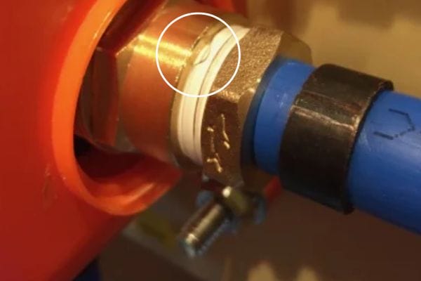
Leak Prevention Strategies
To minimize the risk of leaks:
- Proper Torque: Follow manufacturer torque specifications for each connection type
- Appropriate Sealing Method: Use the correct sealing approach for each thread type:
- Clean Connections: Ensure all sealing surfaces are clean and undamaged
- Alignment: Prevent cross-threading by proper alignment before tightening
- Support: Provide adequate support to prevent stress on connections
Maintenance and Inspection Recommendations
Regular maintenance practices should include:
- Visual Inspection: Check for signs of leakage, corrosion, or damage
- Torque Verification: Periodically verify proper torque on critical connections
- Replacement Schedule: Establish replacement intervals for adapters in critical applications
- Documentation: Maintain records of adapter types and locations for future reference
- Spare Parts: Stock commonly used adapters for emergency repairs
During system modifications:
Relieve pressure before disconnecting any components
Clean connections thoroughly before reassembly
Replace any adapters showing signs of damage
Verify proper function before returning to service
Update system documentation to reflect changes
Common Mistakes and Troubleshooting
Misidentification of Thread Types
Thread misidentification is perhaps the most common error in hydraulic adapter selection:
Prevention Strategies:
- Use thread identification gauges to verify thread type and pitch
- Maintain a reference collection of known thread types
- Train personnel on distinguishing features of different threads
- Label components and ports with thread information
- Document thread types in system schematics
Correction Approaches:
- Develop a systematic identification process
- When in doubt, use adapters rather than forcing connections
- Consider standardizing on fewer thread types where possible
- Create thread identification guides specific to your equipment
Cross-Threading and Installation Errors
Cross-threading can permanently damage components:
Prevention Strategies:
- Always start threads by hand
- Ensure proper alignment before applying torque
- Back off and restart if resistance is felt too early
- Use thread lubricant when appropriate
- Train personnel on proper threading techniques
Correction Approaches:
- Replace damaged components rather than forcing connections
- Use thread repair tools only when replacement isn’t possible
- Inspect both male and female threads for damage
- Consider thread inserts for repaired female ports
Over-Tightening and Under-Tightening Issues
Improper torque leads to connection failures:
Over-Tightening Problems:
- Deformed sealing surfaces
- Cracked components
- Distorted O-rings
- Stripped threads
- Difficult future disassembly
Under-Tightening Problems:
- Leakage under pressure
- Connection loosening from vibration
- Inadequate metal-to-metal contact in flared connections
- Incomplete seal formation in tapered threads
Best Practices:
- Use calibrated torque wrenches
- Follow manufacturer torque specifications
- Consider torque-turn methods for consistent results
- Account for lubrication when determining torque
- Implement torque verification procedures
Conclusion
Understanding hydraulic adapter threads and codes is vital for fluid power systems. With various standards and configurations, proper selection ensures performance, prevents failures, and avoids costly downtime. As the industry moves toward standardization, digital tools, and advanced materials, adapter selection will become more efficient.
FAQ
What is a hydraulic adapter?
A hydraulic adapter connects different types of hydraulic components, often converting thread types or sizes to ensure a secure, leak-free system.
Why are thread types important in hydraulic adapters?
Thread types determine how adapters fit and seal. Using the wrong thread type can cause leaks or system failure.
What are common hydraulic thread standards?
Common standards include BSP, JIC, NPT, ORFS, metric, and SAE, each with unique sealing methods and thread forms.
How can I identify the thread type on an adapter?
You can use a thread gauge, caliper, or a thread identification tool. Manufacturer charts and mobile apps also help.
What do the adapter codes mean?
Adapter codes describe thread type, size, and configuration (e.g., male/female, elbow, tee), making selection easier.
Can I mix different thread standards?
It’s possible with the right adapter, but you must consider pressure ratings, sealing type, and compatibility to avoid issues.