Most one piece fitting complaints can be reduced by controlling product identity, compatibility information, order entry, labeling, picking, and traceability before shipment. A fitting may look correct while having the wrong port dash, hose dash, thread standard, sealing method, or fitting series. That error can produce leakage, damaged threads, assembly rework, or a hose pull-off risk. Effective complaint prevention therefore begins with a complete order line and continues through incoming inspection and dispatch.
Complaints Usually Begin Before the Shipment Leaves
The shipment often reveals a complaint, but the original error may have entered the process much earlier. An incomplete inquiry, ambiguous SKU description, unverified substitution, or mixed warehouse bin can all place the wrong fitting into an otherwise correctly packed carton.
Separate technical and operational causes
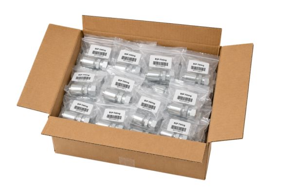
Technical complaints concern whether the supplied part matches the required connection and assembly. They include the wrong thread, seal, hose-side geometry, material requirement, or fitting series. Operational complaints concern execution: a correct SKU may be mislabeled, placed in the wrong carton, short-shipped, mixed with another batch, or sent with incomplete documents. The distinction matters because replacing a label will not correct a compatibility problem, while repeating a thread inspection will not explain why two verified SKUs were mixed during picking.
Control the order line as the first record
Each order line should identify one unambiguous item. A general description such as “one-piece elbow, size 8” is weak because “size 8” may refer to the port side, hose side, or an internal coding convention. The order line should connect the customer reference, controlled part number, fitting series, connection description, port dash, hose dash, angle, material or finish requirement, quantity, and revision when applicable. This record becomes the reference used by order review, warehouse picking, packing, and any later complaint investigation.
Product Identification Errors Create Predictable Complaints
Visual similarity is not reliable product identification. Small differences in thread form, seat, taper, O-ring location, or hose-side design can change function even when two fittings share the same general shape.
Confirm the complete connection
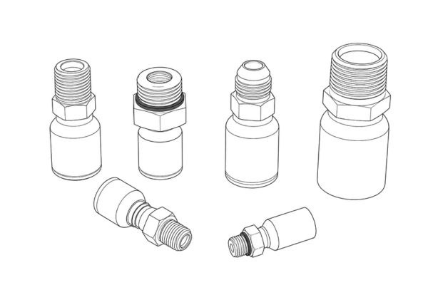
Connection identification should distinguish the thread standard from the sealing method. Review whether the connection is male or female, straight or tapered, and whether sealing occurs on a flare seat, flat face, O-ring, cone, or designed thread interface. Thread diameter and pitch or TPI may also be required. Similar-looking JIC, SAE, NPT, NPTF, BSP, Metric, and other connections must not be accepted as interchangeable from a photograph or approximate diameter.
The port dash and hose dash must be separate fields because they describe different ends of the fitting. A reducer can legitimately combine unlike sizes, and an elbow can share a port end with another part while using a different hose tail. When staff compress both values into one informal “size” field, the warehouse can pick a part that threads into the port but cannot be assembled to the intended hose.
Keep the series and configuration visible
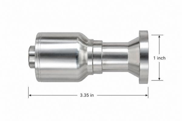
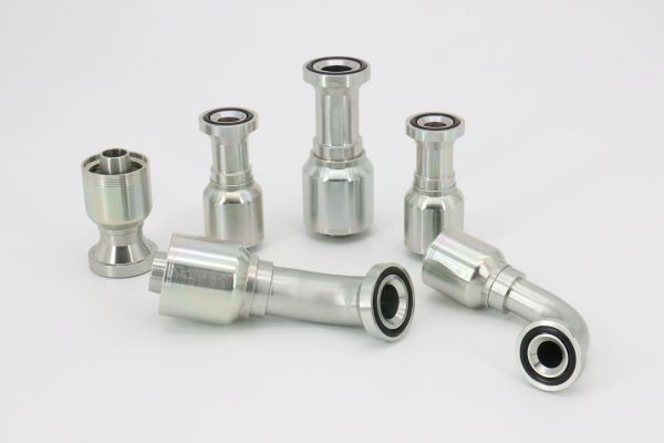
A one-piece fitting is an assembly in which the body or stem and ferrule are preassembled, attached, or retained together; exact construction varies by series. That structure can reduce separate ferrule selection, but it does not prove hose compatibility or the correct crimp specification. The controlled description should therefore include the fitting series as well as straight, 45-degree, or 90-degree configuration and any orientation details that affect installation clearance.
Before an order is released, check these identity fields together:
- Controlled part number and revision or customer cross-reference
- Connection standard, gender, thread measurement, seat, and sealing method
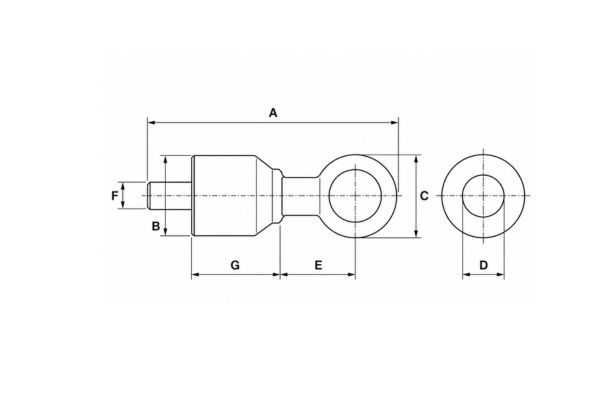
- Port dash, hose dash, fitting series, and configuration angle
- Material, surface finish, marking, and any application-specific requirement
- Clear drawings or verified reference data when a description remains ambiguous
Hose, Ferrule, and Crimp Compatibility Need Their Own Review
A correct port connection can still produce a serious complaint if the hose side is wrong. Suitability belongs to the complete hose, fitting, ferrule, equipment, and die combination, not to the fitting appearance or dash size alone.
Match the documented assembly combination
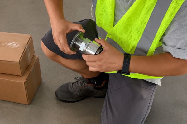
Review the hose manufacturer or compatible specification, hose series, construction, hose ID, dash size, reinforcement, fitting series, ferrule design, crimp equipment, die set, and current crimp data. Two hoses with the same nominal dash can have different constructions or outside dimensions. Likewise, two one-piece fittings with similar tails may belong to different series. A warehouse substitution made only because both labels show the same dash can create incomplete insertion, incorrect compression, cover damage, leakage, or pull-off.
Do not invent a crimp diameter, insertion depth, die, skive requirement, or pressure rating to complete an order. The applicable hose, fitting, and crimp-equipment manufacturer’s current instructions must control the assembly. Pressure suitability is also limited by the lowest-rated component in the finished assembly and is affected by fluid, temperature, impulse, routing, installation, and condition.
Treat safety complaints as controlled inspections
If a complaint involves leakage, thread damage, sealing failure, or possible hose pull-off, the equipment must be stopped, the hydraulic system isolated, pressure and stored energy released, and raised loads secured before inspection. A suspected high-pressure leak must never be checked by hand. An uncertain fitting should not be installed merely to avoid a delivery delay. Preserve the removed parts and packaging when safe so that product identity and batch evidence remain available.
Order Entry, Labels, and Picking Must Use the Same Data
Complaint prevention weakens when sales records, product labels, warehouse bins, and cartons use different naming systems. The simplest control is a shared, controlled identity that follows the SKU through every handoff.
Align records and physical labels
The order entry should generate or reference the same part number used on the bin, inner package, carton, and packing list. Human-readable descriptions should show the fields most likely to be confused, especially connection standard, port dash, hose dash, angle, and series. A barcode can support verification, but it cannot correct inaccurate master data or a label applied to the wrong product.
Mixed stock needs immediate segregation. Loose parts, damaged inner packages, or returned items should not be placed into a normal bin until identity and batch are reconfirmed. When similar fittings are stored near one another, bin locations and scan checks can reduce risk, but the final comparison must still use the order line rather than color, overall length, or visual shape.
Verify before sealing the carton
A final check should compare the picked part, inner label, carton label, quantity, and order line. For high-confusion items, the checker should confirm both dash values and the connection description rather than merely repeating the part number shown on the same label. The carton should retain a batch or lot reference where traceability is required.
Useful dispatch checks include:
- Scan or read the product identity from the part or inner pack, not from memory
- Compare port dash and hose dash as separate fields
- Check straight or elbow configuration and orientation
- Confirm carton contents match the carton and packing-list labels
- Record exceptions, relabeling, mixed packages, or approved substitutions
Incoming Inspection and Batch Records Limit Repeat Risk
Incoming inspection should confirm that received goods match the approved identity and the evidence required for that SKU. It is not a universal test program, and it should focus on characteristics that can cause misidentification, assembly failure, or loss of traceability.
Inspect identity and critical characteristics
Checks may include part number, marking, thread with suitable gauges, critical dimensions against an approved drawing, sealing features, hose-side geometry, ferrule assembly, material evidence, surface finish, packaging labels, and batch documentation. The scope should reflect product risk, history, and the controlled specification. A visually acceptable finish cannot prove the thread, material, pressure suitability, or hose compatibility.
Records must link findings to the received batch rather than to the product family in general. If a later complaint identifies a nonconforming thread or incorrect label, the batch link helps determine which stock requires review. Without it, teams may either miss affected stock or quarantine every unit of a part number unnecessarily.
Use evidence appropriate to the complaint
| Complaint signal | Evidence to check | Preventive control |
| Part will not connect | Thread, gender, pitch/TPI, taper, seat, port dash | Controlled connection description and gauge check |
| Hose cannot be assembled correctly | Hose dash, hose series, fitting series, ferrule, crimp data | Verified assembly combination on the order record |
| Correct part in wrong carton | SKU, inner label, carton label, picking record | Scan and independent pack verification |
| Finish or marking differs | Approved requirement, retained evidence, batch documents | Incoming inspection linked to batch |
| Leakage after installation | Seal, thread condition, assembly data, installation evidence | Technical review plus safe failure inspection |
Classify and Investigate Complaints by Evidence
A complaint record should state what failed, where the discrepancy was found, and which order line, SKU, carton, and batch are involved. Vague labels such as “quality problem” prevent the team from identifying whether the cause was technical, documentary, logistical, or related to assembly or application.
Contain first, then determine cause
First identify potentially affected stock and stop further use or dispatch when the reported condition may create risk. Preserve photos, labels, measurements, documents, and samples without asking anyone to dismantle a pressurized system. Then compare the received item with the controlled order record and approved specification. A complaint should not automatically be assigned to production, warehouse, or user error before evidence is reviewed.
Classify the finding in practical terms: wrong ordered specification, order-entry error, incorrect product, picking or packing error, labeling discrepancy, batch nonconformity, document mismatch, assembly incompatibility, installation damage, or application mismatch. More than one factor may contribute, but each proposed cause should have supporting evidence.
Correct the system, not only the shipment
Replacing the disputed parts may restore the order but does not prevent recurrence. Corrective action should address the point where the error entered or escaped. That may mean revising a product description, separating two bins, adding a required dash field, correcting label master data, changing an inspection characteristic, or requiring technical approval before substitutions.
Turn Complaint Data Into Better Future Orders
Complaint data becomes useful when it changes a repeatable control. Count and review causes by SKU family, error type, process step, and batch evidence without inventing performance claims or hiding low-frequency safety problems.
Look for repeated ambiguity
Repeated wrong-size complaints may indicate that port dash and hose dash are displayed poorly. Repeated “does not fit” complaints may point to weak thread or sealing descriptions. Repeated carton discrepancies may reveal mixed bins or labels created outside the controlled item record. The response should match the pattern instead of adding a generic final inspection to every product.
Use a neutral prevention checklist
Before releasing a repeat order, confirm:
- The order line identifies the connection, seal, port dash, hose dash, series, angle, material, and finish required
- Hose compatibility and current crimp data are available when assembly suitability is part of the decision
- Product, bin, inner-pack, carton, and document identities agree
- Incoming checks and retained evidence are linked to the relevant batch
- Previous complaint actions have been applied to the affected SKU and process step
- Any substitution has separate technical approval rather than informal visual acceptance
Conclusion
Reducing complaints requires a connected control chain, not a single final inspection. Begin with a complete order line that separates connection identity, port dash, hose dash, sealing method, fitting series, configuration, and material requirements. Carry that identity through labels, bins, picking, packing, incoming inspection, and batch records. When a complaint occurs, contain possible risk, preserve evidence, and trace the finding to the order line, SKU, carton, and batch before assigning a cause. Correct the step that created or failed to detect the error, then apply the lesson to future orders. This disciplined approach reduces one-piece fitting distributor complaints while keeping compatibility and safety decisions based on verified technical data rather than appearance, speed, or price.
Frequently Asked Questions
Can one-piece construction prevent ferrule complaints?
No, one-piece construction only keeps the fitting body or stem and ferrule assembled or retained together. The fitting series still must match the hose construction, size, equipment, dies, and current crimp specification.
Is a matching part number enough for order approval?
No, a part number is useful only when its controlled definition and revision are known. Cross-references, legacy codes, or customer numbers should be checked against the connection, hose side, geometry, and material requirements.
Should every complaint trigger inspection of all inventory?
No, the containment scope should follow evidence and traceability. A reliable link to the order, SKU, carton, and batch helps isolate affected stock while safety-critical uncertainty may justify broader temporary quarantine.
Can barcode scanning eliminate picking errors?
No, scanning verifies the data encoded in the system but cannot correct wrong master data, mislabeled stock, or an approved SKU that does not match the application. Physical identity and controlled technical fields still require review.
What evidence is most useful for a leakage complaint?
The most useful evidence connects the fitting and assembly to the order, batch, connection, sealing method, hose series, crimp data, and safe inspection findings. Photos alone can support screening but cannot prove final compatibility or root cause.