An unmarked hose end can stop short inside a fitting without leaving an obvious external sign. To check hose insertion depth before crimping one-piece fittings, use the exact manufacturer instruction for the approved hose-and-fitting combination, transfer its specified insertion reference to a visible external mark, and verify the mark’s final position before the assembly enters the crimper. The mark is a position check, not a substitute for compatibility or crimp data. A disciplined hold point helps detect incomplete engagement, incorrect pairing, debris, preparation errors, and movement during handling before those problems are hidden by crimping.
Begin with the Unmarked-Hose Failure
Do not crimp an assembly when the hose has no reliable external insertion reference. Once the ferrule is compressed, the shop may be unable to determine whether the cut end reached the required internal position without destructive examination or another approved verification method.
Why appearance can mislead
A hose may feel as though it has reached a stop even when its path is blocked by debris, damaged reinforcement, an incompatible stem, or poor preparation. The ferrule can also hide the cut end, so the operator cannot confirm engagement by looking at the finished assembly. A smooth insertion feel is useful process information, but it does not prove that the specified position was reached.
Incomplete insertion can change which portion of the stem and ferrule engages the hose. That creates uncertainty about retention, sealing, reinforcement capture, and the validity of the crimp process. Do not resolve that uncertainty by adding force, choosing a deeper position from memory, or assuming that the crimp operation will pull the hose into place.
Establish a pre-crimp hold
Place the assembly in a hold condition whenever the external depth mark is missing, unclear, displaced, or inconsistent with the instruction. Keep it out of the crimper until the hose and fitting identities, preparation, reference position, and insertion result have been verified. This is faster and safer than investigating an already crimped assembly with an unknown internal position.
Separate the Three Position References
The cut end, the specified insertion reference, and the external depth mark are related but not interchangeable. Clear terminology prevents operators from measuring from the wrong feature.
Cut end and specified insertion reference
The cut end is the physical end of the prepared hose. It should be square and prepared according to the current hose, fitting, and equipment instructions, without loose debris or damage that invalidates the assembly. The specified insertion reference is the position defined by the applicable manufacturer procedure for that exact combination. Depending on the design, the controlling reference may relate to an internal stop, a fitting feature, or another documented location; do not invent one from external appearance.
The required distance is product-specific. It can change with hose series, size, fitting code, and design revision. Never publish or use a universal insertion value, and never borrow a value from another fitting series merely because the hose dash designation matches.
External depth mark
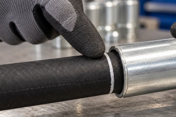
The external mark transfers the approved insertion reference to a location that remains visible after the hose enters the fitting. It allows the operator to compare the hose position with a known fitting feature before crimping. The mark must be narrow enough to make the acceptance decision clear and durable enough to survive normal handling until the check is complete.
Insertion depth is not crimp diameter. The first describes the axial position of the hose within the fitting before crimping; the second is a dimensional result of compression measured by an approved method after or during the controlled process. A correct depth mark cannot authorize a crimp target, and a correct crimp measurement cannot prove that insertion was correct.
Prepare and Mark from Current Instructions
Use only the current approved assembly instruction for the exact hose, fitting, and size. A shop drawing, traveler, or work instruction should identify the source and revision so the operator does not work from an uncontrolled note.
Verify identity before measuring
Read the hose layline and part identification, then match them to the traveler. Confirm the hose manufacturer, series, construction, ID or dash, and applicable lot record. Confirm the complete fitting code, series, size, orientation, end connection, and lot or traceability mark when required. A one-piece fitting keeps its stem and ferrule together, but it does not make the fitting compatible with every hose of the same nominal size.
Before marking, verify:
- the controlled instruction names the hose and fitting combination;
- the instruction revision is current at the workstation;
- the hose cut and any required preparation meet that instruction;
- the reference feature and measurement method are understood;
- the measuring device is suitable, identifiable, and in valid condition.
Transfer the reference consistently
Measure from the documented hose-end reference using the approved method. Place a clear circumferential or otherwise specified mark at the required location without damaging the cover. If the procedure uses a fixture or gauge, confirm that it is the correct one for the assembly and that it is clean and undamaged.
Do not broaden the mark to hide variation. If two operators cannot identify the same edge of the mark, refine the marking method before production. Record an unclear mark as a process problem rather than interpreting it in whichever way permits the assembly to continue.
Insert the Hose Without Improvisation
Insert the prepared hose using the method specified for the combination. Stop when resistance, alignment, or the final mark position differs from the approved process.
Control alignment and motion
Keep the hose and fitting aligned as required so the hose does not catch on the stem or distort at the ferrule entrance. Apply only the approved preparation and insertion method. Do not use unapproved lubricants, heat, aggressive twisting, hammering, or excessive force to make a difficult combination assemble.
Watch the external mark throughout insertion. The final relationship between the mark and the defined fitting feature must match the instruction. If the mark disappears farther than expected, remains short of the reference, or becomes angled around the circumference, stop and investigate rather than averaging the position visually.
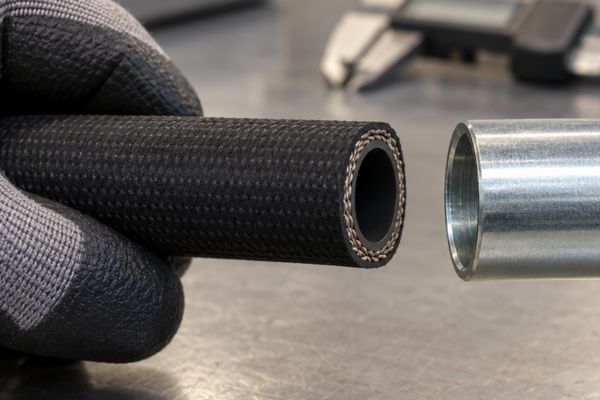
Do not convert feel into acceptance
Operators often develop a useful sense of normal insertion effort, but feel remains a screening signal. Variations in hose temperature, cut quality, cleanliness, construction, and component condition can change resistance. The visible reference and approved instruction remain the acceptance basis unless another documented method applies.
Investigate Any Blocked or Short Insertion
A hose that will not reach the specified position may reveal a pairing or preparation problem. Treat the obstruction as evidence to examine, not as resistance to overcome.
Check the component pairing first
Compare the hose layline and complete fitting code with the traveler and compatibility record again. Similar-looking fittings can belong to different series, and matching dash numbers do not prove compatible stem and ferrule geometry. Confirm that the ferrule is correctly retained with the intended stem and has not been mixed with another assembly.
Then inspect for:
- debris inside the hose or fitting;
- an unsquare, collapsed, frayed, or otherwise damaged hose end;
- preparation that does not match the specified skive or no-skive process;
- a deformed fitting entrance, stem, or ferrule;
- an incorrect cut-end reference or depth mark;
- interference caused by an unapproved hose-and-fitting combination.
Do not reuse a component that the applicable procedure requires to be rejected after attempted assembly. Do not remove material, alter the stem, expand the ferrule, or substitute a different preparation merely to reach the mark.
Escalate unresolved resistance
If identity and visible condition are correct but the hose still does not reach the reference, quarantine the parts and ask the responsible technical authority to review the controlled compatibility and assembly data. Preserve the hose, fitting, labels, and observations. That evidence is more useful than a part that has been forced together or crimped before the cause is understood.
Verify Position Before the Crimper
The final insertion check must occur after normal handling but before the assembly is placed for crimping. This catches movement that occurred after the initial mark aligned.
Inspect the mark at the hold point
Place the assembly in the orientation required by the work instruction. Compare the full mark with the fitting reference, checking around the hose rather than from only one convenient viewing angle. Confirm that the hose has not backed out, that the mark is still legible, and that the fitting orientation remains correct for elbows or other clocked ends.
Use a simple STOP–VERIFY–RELEASE sequence:
- STOP: Keep the assembly outside the crimper when the mark is missing, displaced, or ambiguous.
- VERIFY: Reconfirm identity, reference, preparation, and final position against the current instruction.
- RELEASE: Allow crimping only when the defined acceptance condition is met and recorded as required.
The operator should not hold the hose at the mark and then release it into a setup that can disturb its position. Design the handoff so the verified relationship is maintained while the assembly is loaded.
Confirm machine setup separately
After insertion release, verify the crimper, die set, program or setup, calibration status, and current crimp instruction for the exact assembly. Do not treat insertion approval as approval of the machine setup. Both gates must pass independently before the irreversible compression step begins.
Protect the Indication During Handling
Insertion can change between the first check and the crimp cycle. Handling controls are therefore part of the verification method, not housekeeping details.
Prevent back-out and mark damage
Avoid pulling on the hose, carrying the assembly by the fitting, stacking uncrimped pieces in a way that shifts them, or wiping away the mark. Keep uncrimped assemblies separated from finished product and use a rack, tray, or orientation that prevents their own weight from changing engagement. For assemblies with elbow orientation requirements, protect both insertion and clocking.
If the mark smears or is covered, do not redraw it by guessing where the original line was. Return to the approved measurement step. If the hose has backed out, follow the controlled disposition or reassembly procedure; do not simply push it back and proceed unless the procedure explicitly permits that action and the parts remain acceptable.
Keep status visible
Use a traveler, tag, or electronic status that distinguishes prepared, insertion-verified, crimp-ready, crimped, and held assemblies. Status control prevents an unchecked piece from entering the machine when several similar hoses are on the same bench.
Record the First Piece and Release the Run
First-piece verification demonstrates that the documented method can be followed with the actual components and setup at the start of the run. It does not eliminate checks on later assemblies or authorize undocumented variations.
Capture evidence that can be traced
Record the hose and fitting identities, lot information when required, instruction revision, insertion-check result, machine and tooling identity, setup record, and operator or station. The record should show that insertion was checked before crimping and that the finished first piece met the applicable measurement and inspection requirements.
If the first piece fails, contain it and any related work. Separate a suspected insertion problem from a crimp setup, measurement, tooling, or component problem. Do not re-crimp or salvage the assembly without an approved procedure.
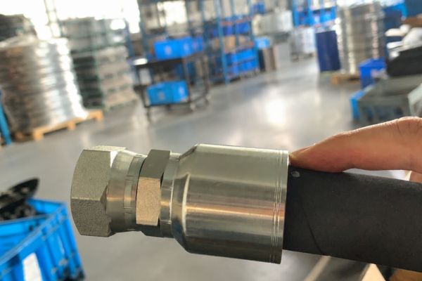
Use a pre-crimp hold-point sequence
Before each release, confirm in order:
- exact hose, fitting, and traveler match;
- cut end and preparation are acceptable;
- depth reference was taken from the current instruction;
- external mark is clear and final position is acceptable;
- handling has not disturbed insertion or orientation;
- crimper, tooling, setup, and instruction are separately approved;
- required first-piece or production record is complete.
This sequence makes the hidden internal position visible through controlled evidence. It also gives the operator a clear reason to stop without improvising when evidence is incomplete.
Conclusion
Reliable insertion control depends on a visible reference tied to current manufacturer instructions for the exact hose-and-fitting combination. Identify the components first, prepare and mark the hose consistently, insert without unapproved force, and investigate any unexpected resistance. Check the mark again after handling and immediately before the crimper, while keeping the crimp setup as a separate approval gate. Record the first piece and preserve component, process, and revision traceability. Never replace missing data with a universal depth or assume that a correct finished crimp diameter proves hose engagement. A controlled hold point for hose insertion depth before crimping one-piece fittings prevents a hidden position error from becoming a questionable finished assembly.
Frequently Asked Questions
Can I use the same insertion depth for fittings with the same dash size?
No, nominal dash size does not establish a universal insertion depth. Use the current instruction for the exact hose manufacturer, hose series, fitting code, size, and design revision.
Is the edge of the ferrule always the insertion reference?
No, the approved reference depends on the fitting design and manufacturer procedure. Do not choose an external feature unless the controlled instruction identifies it.
Can a correct crimp diameter prove that the hose was fully inserted?
No, crimp diameter and insertion depth describe different conditions. A dimensional crimp result does not reveal whether the hose cut end reached its specified position before compression.
What should I do if the mark moves while loading the crimper?
Stop and return the assembly to the pre-crimp verification step. Recheck identity, position, and part condition, then follow the approved disposition or reassembly procedure.
Should I force a hose that stops short of the depth mark?
No, unexpected resistance requires investigation. Check pairing, cleanliness, cut quality, preparation, and component condition, and escalate when the cause cannot be resolved through the approved instructions.