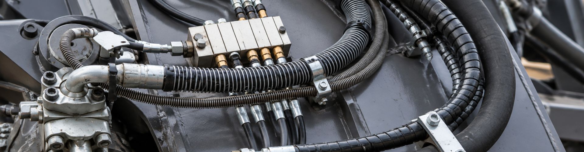
How to Replace One-Piece Fittings on Older Equipment

How to Replace One-Piece Fittings on Older Equipment?

One-piece hydraulic hose fittings can simplify replacement assembly work when the fitting series, hose, connection, and crimp specification are verified together. Their preassembled construction reduces one separate component-selection step, but it does not resolve seized threads, repair damaged ports, or make similar-looking hose ends interchangeable. On older equipment, the immediate challenge is often identifying what failed before ordering what appears to be the same part.

What One-Piece Construction Changes

A one-piece fitting combines the stem or body and ferrule into a preassembled or retained unit. It describes the hose attachment construction, rather than a universal thread type or pressure class.
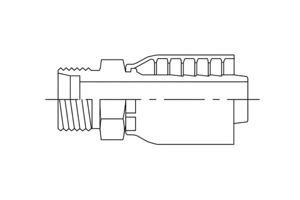
metric 24° thread crimp fitting

Separate the Ferrule Arrangement From the End Connection

The stem enters the hose, while the ferrule surrounds the prepared hose end and is compressed during the specified crimping process. How the ferrule is retained and how the stem engages the hose depend on the fitting series, so the term “one-piece” should always be followed by a product identification.

Having the ferrule supplied with the stem can reduce the need to pick a separate ferrule, which is useful when preparing repeat assemblies from approved parts. However, you must still select the correct fitting family, hose size, and connection configuration. A female swivel, rigid male end, straight fitting, and elbow can all require different identification checks even when their hose attachment construction is described the same way.

Diagnose the Old Connection Before Choosing a Replacement

A stuck fitting, a broken fitting, and a connection that turns without tightening are different symptoms. None identifies the cause or establishes whether a new hose end alone will complete the repair.

Use the Symptom to Define the Inspection

First establish the safe maintenance condition: stop and isolate the equipment, control supported loads, and release hydraulic pressure and stored energy according to the equipment manufacturer’s procedures. A stopped pump or one gauge reading cannot replace the required verification process, and loosening a fitting is not an improvised depressurization method.

Trace the assembly from the hose fitting through any adapter to the equipment port, then identify the joint that is supposed to separate. Corrosion outside the joint does not establish the condition of the engaged threads, while rounded wrench flats can prevent removal without proving that the threads have seized. Likewise, a broken part requires assessment of the remaining piece and surrounding body, rather than an immediate assumption of fatigue or a promise that an extractor will remove it without damage.

Identify the Thread and the Actual Seal

The equipment end must match the complete connection design. Thread engagement alone cannot confirm that the sealing surfaces are compatible or that the fitting is suitable for the application.

Measure Before Assigning a Connection Standard

Record male or female configuration, straight or tapered thread, measured diameter, and pitch or threads per inch before comparing the fitting with a reliable identification reference. Then confirm the connection standard, seat angle, sealing face, and any O-ring or washer arrangement; measuring an internal thread requires the appropriate reference method, rather than treating its opening diameter as a nominal size. JIC, SAE 45-degree flare, NPT/NPTF, BSPP/BSPT, ORFS, ORB, metric, DIN, and JIS descriptions must lead to a specific verified connection.

Threads can provide retention while a separate face, cone, or elastomeric element provides the seal, depending on the connection design. Parker’s technical training resources treat O-ring face seal, flare, flareless, and parallel-thread port connections as distinct assembly subjects, reinforcing the need to identify more than diameter and pitch. Do not use thread tape or additional tightening to compensate for an unidentified sealing interface; follow the instructions for the confirmed connection.

Photographs help narrow the possibilities, especially when markings are incomplete, but they do not replace dimensional and sealing checks. Capture the entire fitting, the thread, and the sealing face before cleaning or handling obscures useful evidence, and record the original part number where available. If damage prevents a reliable measurement, use the mating-component documentation or equipment parts information rather than forcing a sample into the port as a thread gauge.

Match the Fitting Series to the Hose

The correct equipment connection is only half of the replacement decision. The hose attachment must belong to an approved hose-and-fitting combination with a validated assembly procedure.
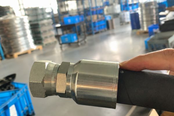
crimp Fitting Assembly

Check the Complete Crimp Specification

Start with the hose manufacturer and series, construction, and inside diameter or dash size, then identify the fitting stem and ferrule design approved for that hose. Two hoses with the same inside diameter can require different fittings or preparation, so equal dash sizes do not establish compatibility.

Obtain current assembly data covering the following items before preparing the hose:

Use the specification for that combination rather than copying settings from a similar ferrule or measuring a used assembly as the manufacturing target. A machine setting and a finished crimp measurement serve different purposes, and the prescribed checks remain necessary after the machine cycle.

Confirm the Replacement Fits the Application

A fitting that matches the hose and thread can still be unsuitable for the installation. Review the operating conditions and installed geometry before approving the replacement assembly.

Evaluate Pressure, Environment, and Clearance Together

Confirm the required working pressure against the approved hose assembly and every relevant component in the connected pressure path, including the hose, fittings, adapters, and port. The lowest applicable rating sets a ceiling; it does not validate an otherwise unapproved combination, and burst pressure is not allowable working pressure. Temperature, fluid compatibility, pressure impulse, corrosion, vibration, and mechanical loading also affect suitability, so use the selected manufacturers’ application information rather than a generic rating assigned to all one-piece fittings.

Compare overall length, elbow angle, orientation, wrench access, and the space needed to install and remove the assembly without twisting or forcing it. A replacement with the same thread can have a different stem length or elbow envelope, changing the hose route near a bracket or adjacent line. Check routing, bend requirements, movement, and support against the hose and equipment instructions, and do not assume that adding another adapter automatically solves a clearance problem without introducing further checks.

Material and surface finish should also be selected for the actual fluid and external exposure, rather than appearance or a universal preference for one alloy. Where an O-ring is part of the connection, confirm the specified seal material and dimensions separately from the fitting body material. Laboratory corrosion-test hours, when provided for a particular product, should not be translated into a promised field service life under unspecified conditions.

Build a Repair Package That Can Be Verified

Complete identification and documented assembly requirements make a replacement reviewable. They also prevent an uncertain emergency substitution from becoming an approved stock item through repeated use.
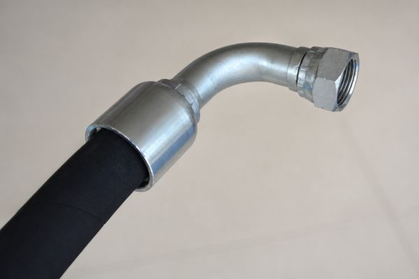
identify connection

Prepare the Technical Confirmation Checklist

Assess the port, sealing surfaces, and surrounding body after removal before treating installation as routine. A new fitting cannot restore missing internal threads, and running a tap through a damaged port does not by itself establish that the connection is fit for pressure service. Thread restoration, inserts, or port modifications require an approved repair assessment, including contamination control and the required inspection; replacement of the affected component must remain an option.

For a replacement inquiry or internal work order, collect the information that answers the unresolved technical questions:

Do not close gaps with statements such as “same as the sample” when the sample is damaged or its service history is unknown. Identify which details are confirmed and which require manufacturer or engineering approval, and keep unverified alternatives separated from released parts. Before returning the equipment to service, follow the prescribed installation, inspection, and commissioning procedure; never use a hand to check for pinhole leakage or use mismatched components as a temporary high-pressure repair.

Conclusion

One-piece hydraulic hose fittings are useful when their preassembled construction supports an identified, approved hose assembly. They do not remove the need to diagnose the old connection, inspect the equipment port, or verify the replacement’s sealing interface. The most reliable repair starts with confirmed information: hose series, fitting series, thread and seal details, operating conditions, installation dimensions, and current crimp data. Correct matching matters more than a familiar appearance or the lowest unit price. Gather those details before ordering, keep unresolved alternatives out of released stock, and follow the equipment’s return-to-service requirements. That gives the next repair a documented starting point instead of another uncertain sample to copy.

Frequently Asked Questions

Can the ferrule be removed and replaced separately on a one-piece fitting?

Do not assume it can. The retained ferrule arrangement is part of the specific fitting design, and separating or modifying it is not a substitute for selecting the correct approved assembly. Follow the product manufacturer’s instructions.

Can an old crimped fitting be transferred to a new hose?

Do not reuse a permanent crimp fitting unless its manufacturer explicitly permits that procedure. “One-piece” does not mean reusable, and removing an old hose does not establish that the fitting remains acceptable. Field-attachable products have separate assembly and reuse requirements.

Does a swivel nut allow the hose to rotate continuously during operation?

An assembly swivel should not be assumed to function as a live rotary joint. Check whether the product is intended only to assist connection and orientation or is specifically rated for operational rotation. Resolve repeated hose twisting through the approved routing and connection design.

Can a cross-reference number establish that an alternative is interchangeable?

No; use it as an identification lead. Confirm the hose compatibility, connection geometry, pressure and temperature suitability, installation dimensions, and assembly data for the proposed part. Similar catalog descriptions do not replace documented approval.

What should happen if the hose markings are unreadable?

Treat the hose identification as unresolved. Check equipment records, assembly labels, or traceable parts information instead of selecting fittings from inside diameter alone. If compatibility cannot be established, obtain an approved replacement assembly specification.

How to Inspect a Multi-SKU Shipment of One-Piece Fittings

How to Inspect a Multi-SKU Shipment of One-Piece Fittings

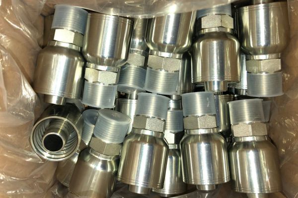
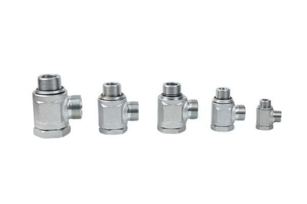
A pallet containing several nearly identical elbows, swivel ends, and dash sizes should not move directly into stock. To inspect a multi-SKU shipment of one-piece fittings, receiving must preserve carton identity, reconcile documents, separate every SKU and lot, apply the approved inspection scope to each population, and quarantine discrepancies before any bin release. The main risk is not only a defective part; it is a correct part under the wrong label, a mixed batch, or an inspection result applied to the wrong SKU. A checkpoint workflow keeps evidence attached to each carton from unloading through final disposition without inventing one sampling rule for every product.

Freeze Shipment Identity Before Breaking Down the Pallet

Receiving control begins while cartons still retain their original relationship to the shipment. Moving loose boxes to several areas too early can erase the evidence needed to resolve a shortage, mix, or label conflict.

Packing area

Create a receiving boundary

Assign a receipt or inspection identifier to the shipment and designate a controlled staging area. Photograph the pallet, external labels, damage, wrap, and carton arrangement when the procedure requires it. Record arrival condition before removing labels, replacing packaging, or combining partial cartons.

Keep the shipment unavailable to production and picking until disposition is complete. If urgent demand exists, use an authorized partial-release process that identifies exactly which SKU, lot, carton, and quantity were accepted; do not treat urgency as blanket approval of the pallet.

Map cartons to purchase-order lines

Create a carton map or receiving list that links each physical carton and inner pack to the purchase-order line, packing-list entry, supplier item, expected quantity, and lot or batch marking. Use temporary receiving labels only when they do not cover original information and are clearly distinguished from final stock labels.

Do not assume adjacent cartons contain the same item. A mixed pallet can include several fitting angles or connections with nearly identical packaging. Maintain one physical location or clearly bounded zone per identified SKU and lot while documents are checked.

Reconcile the Purchase Order, Packing List, and Labels

Document agreement is the first release gate. Quantity reconciliation alone cannot detect the wrong model listed under a plausible description.

Compare item-level fields

For every purchase-order line, compare full SKU, description, hose-side size, port-side connection, angle, material or finish when specified, ordered quantity, supplied quantity, lot or batch, and required document references. Check whether the packing list uses the buyer’s code, supplier code, or both, and confirm the approved cross-reference.

Review carton and inner-pack labels against that same line. A correct outer label with conflicting inner labels is a mix signal. A shortened description such as “female fitting” or “90-degree flange” is not enough when several products share that wording.

For each order line, verify at least:

Resolve overages, shortages, and substitutions

Record quantity differences by SKU and lot rather than balancing the total shipment. An overage of one fitting must not hide a shortage of another. If a substituted code appears, hold it until purchasing and technical authorities verify the approved change and product definition.

Preserve commercial and technical documents with the receipt. Missing certificates or reports should be evaluated only when they were required by the order; their presence does not replace physical identity and condition checks. Never create acceptance evidence by renaming an unrecognized document.

Verify SKU, Dash, Angle, and Connection Identity

Physical verification should confirm that the contents match the label and controlled product definition. It should not attempt to identify every fitting from appearance alone.

Use a SKU-specific comparison

Compare product markings and selected features with the current drawing, approved sample, item master, or inspection instruction for that SKU. Check straight, 45-degree, or 90-degree form; hose dash; port dash; male or female construction; swivel or fixed end; thread form; seat or seal type; and relevant stem and ferrule features.

Dash labels must remain attached to the correct side of the description. Port size and hose size are not automatically equal. Similar ferrules or body shapes also do not prove that two products belong to the same hose-fitting series.

Escalate look-alike conflicts

If a carton contains more than one visible geometry, marking, finish, or size, stop removal and preserve the pattern. Do not sort only by eye when final identity requires thread gauges, dimensional checks, drawings, or traceable codes. Place the affected carton and any loose pieces in quarantine.

A photo can document the comparison but cannot prove pitch, taper, seat angle, material, internal stem geometry, or hose compatibility. Use suitable controlled measurement methods and current specifications for the features required by the inspection plan.

Set Inspection Scope by SKU and Lot Risk

Sampling and characteristic selection should follow the organization’s approved plan, product risk, and purchase requirements. There is no universal sample count that fits every shipment.

Keep populations separate

Define the inspection population by SKU and lot or another approved traceability unit. Do not pool samples from multiple SKUs merely because they share a product family. A passing result for one dash size, connection, or lot cannot release another.

Risk inputs may include new item status, first receipt, drawing revision, changed source, past nonconformity, mixed or damaged packaging, application consequence, lot size, supplier history, and characteristic criticality. Record which factors drove normal, reduced, expanded, or full inspection under the approved system.

Select characteristics with consequences in mind

Identity and sealing errors can have different consequences from nonfunctional appearance variation. The SKU-specific plan may call for document review, visual condition, thread and seat verification, selected critical dimensions, ferrule or stem features, finish, marking, cleanliness, or other requirements.

Do not downgrade a required check because the gauge is unavailable. Hold the population until suitable equipment and qualified inspection are available. Conversely, do not invent dimensions or tolerances when the drawing does not provide them; request the controlling specification.

Inspect Packaging, Protection, Finish, and Damage

Packaging is part of the receipt evidence because it can explain contamination, corrosion, impact, and mixing. Review it at carton, inner-pack, and component levels.

Follow exposure from package to part

Check for crushing, punctures, water marks, chemical or oil contamination, torn bags, failed dividers, missing caps, loose parts, and foreign material. Note whether damage affects one carton, one inner pack, one layer, or the entire pallet. Keep the pattern linked to the SKU and lot.

On the fitting, inspect exposed threads, seats, O-rings, machined faces, body, ferrule, plating, and internal openings as required. Do not polish, chase threads, add lubricant, replace seals, or clean aggressively without an approved procedure; those actions can alter evidence or create a new condition.

thread protection

Separate cosmetic and functional questions

Finish shade or a light rub may be cosmetic under one specification, while corrosion, flaking, dents, damaged thread entry, or a scratched sealing face may affect function. Describe the location and type of observation, then compare it with approved acceptance criteria. Do not invent a visual limit.

If the effect is unclear, place the affected population on hold and request technical disposition. An acceptable appearance does not prove material, pressure rating, thread identity, or hose-and-crimp compatibility.

Quarantine Discrepancies and Preserve Traceability

Quarantine must prevent both physical use and administrative release. Moving a discrepant carton aside without changing its system status leaves a path for accidental picking.

Contain the right scope

Identify the SKU, lot, carton, inner pack, quantity, receipt, and reason for hold. Separate affected material from accepted and uninspected populations. If loose parts could have crossed a boundary, expand containment to the last point where identity was verified rather than guessing which pieces are involved.

Use clear hold labels and a controlled location. Do not place rejected or questionable fittings in an active stock bin, return them to an open carton, or mix them with samples awaiting measurement.

Preserve objective records

Record the exact observation, specification reference, sample identity, instrument, measurement result where applicable, photographs, inspector, date, and related documents. “Wrong fitting” is less useful than a statement that names the label conflict or measured feature.

A quarantine record should keep together:

Route the nonconformance through authorized review for return, sort, re-inspection, concession, rework, or rejection as permitted. Receiving personnel should not change labels, repair threads, replace seals, or accept a substitution without documented authority.

Release Accepted Material to the Correct Stock Bin

Stock-bin release is a separate checkpoint after inspection. The accepted product, label, system item, lot, quantity, and physical location must agree.

Prevent the last-step mix

Before movement, reconcile accepted, held, rejected, sampled, and missing quantities for each SKU and lot. Apply final internal labels through the approved method while retaining required supplier and traceability information. Scan or independently verify bin location when similar items are stored nearby.

Do not combine lots unless the inventory and quality procedures allow it and traceability remains adequate. Close cartons and restore approved protective packaging before storage. Partial cartons need clear content and quantity identification.

Use a receiving control table

The table is a workflow aid, not a replacement for SKU-specific inspection criteria or a statistical sampling plan.

Maintain a SKU-by-SKU Receipt Log

The final log should let another person reconstruct what arrived and why each population was released or held. Use one row or linked record per SKU and lot.

Capture purchase order and line, receipt identifier, supplier and buyer item codes, full description, SKU, lot, expected and received quantities, carton IDs, drawing or specification revision, inspection scope, sample IDs, required characteristic results, packaging observations, nonconformance reference, accepted quantity, held quantity, rejected quantity, stock location, inspector, reviewer, and date.

Link photographs, reports, and concessions rather than copying uncontrolled values into notes. Where a field is not required, identify it as not applicable; where evidence is missing, identify it as missing. A blank cell should never quietly mean “accepted.” Retain the log according to the quality system so later complaints, assembly issues, or stock checks can be traced to the correct receipt.

Conclusion

Multi-SKU receiving succeeds when identity remains attached to every carton, sample, result, and disposition. Freeze the pallet record, reconcile each purchase-order line, and separate populations by SKU and lot before inspection. Verify physical identity against controlled product data, then apply the approved risk-based scope without pooling unlike parts or inventing sample plans. Packaging damage, label conflicts, mixed geometry, failed checks, and missing evidence require visible physical and system quarantine. Reconcile all quantities again before releasing accepted material to the correct bin. To inspect a multi-SKU shipment of one-piece fittings reliably, preserve the carton map, inspection evidence, nonconformance records, and SKU-by-SKU receipt log so no correct result is assigned to the wrong product.

Frequently Asked Questions

Can samples from similar SKUs be combined into one inspection lot?

No, not unless an approved plan explicitly defines that population and technical basis. Similar appearance or shared family names do not make different SKUs or lots equivalent.

Should every fitting in a multi-SKU shipment be measured?

Not automatically. Follow the approved risk-based inspection and sampling plan for each SKU and lot, expanding scope when defined risk or findings require it.

Can an outer-carton label release the inner packs?

No, the inner contents and labels still need the verification required by the receiving procedure. A correct outer label can conceal mixed or mislabeled inner packages.

What should happen to a carton with two fitting geometries?

Quarantine the carton and preserve its contents, labels, and location pattern. Do not visually sort and release parts unless an authorized method establishes identity and disposition.

May accepted lots be combined in one bin?

Only when inventory and quality procedures permit it and required lot traceability remains intact. Similar fittings should never be combined in a way that creates picking or investigation ambiguity.

Female Swivel vs Live Swivel When Do You Need Each

Female Swivel vs Live Swivel: When Do You Need Each?

No, both types should not be assumed to rotate during operation. In the female swivel vs live swivel comparison, the central difference is intended motion: a typical female swivel nut turns to assemble and tighten a stationary connection, while a live swivel joint is specifically designed and documented for relative rotation under defined service conditions. Free hand rotation before tightening does not convert a female swivel hose fitting into a dynamic joint. The sealing arrangement, bearings or guiding features, operating loads, pressure and fluid limits, rotation pattern, installation, and maintenance requirements must all be verified for the exact product.

Start With the Motion the Connection Must Perform

Selection should begin with a written motion profile, not with the word “swivel.” Determine whether rotation occurs only during installation, occasionally for positioning while depressurized, or repeatedly while the circuit operates.

Live Swivel Fittings Types

Define installation-only movement

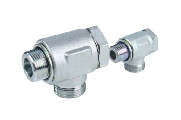
A female swivel nut commonly rotates around the fitting body so the connection can be threaded onto a male mate without twisting the hose. Once tightened to the approved procedure, the nut and mating connection form a stationary joint. The hose and fitting body are not thereby approved to rotate continuously relative to the equipment.

This installation function is valuable because it allows alignment and wrenching, but it has a clear limit. Any remaining equipment movement should be managed by suitable hose routing, bend allowance, supports, and components designed for that motion—not by expecting the tightened nut to act as a bearing.

Define live relative rotation

A live swivel is selected when the application requires relative angular movement during use, within the exact design’s documented conditions. Depending on the product, that motion may be intermittent, oscillating, slow, or otherwise limited. The term does not guarantee unlimited speed, continuous duty, every rotation angle, or operation at every pressure and temperature.

Specify the axis of rotation, angular travel, direction changes, speed or frequency, duty cycle, external loads, hose reaction, and whether motion occurs under pressure. These inputs allow the product’s current documentation to be compared with the real application.

The motion description should include:

Understand What a Female Swivel Nut Actually Does

The nut is an assembly feature that creates the clamping force and alignment needed for its designed sealing interface. Its ability to turn before final tightening must not be confused with the capability of the completed joint.

Rotation supports connection assembly

During installation, the nut can advance on the mating thread while the hose end remains better aligned. The actual seal may occur at a flare, cone, flat face, O-ring, or another designed surface, depending on the exact connection. Thread identity, seat geometry, sealing method, and mating-part condition all require confirmation.

After tightening through the approved procedure, the connection should be treated as fixed unless its documentation explicitly states otherwise. Turning the nut under service movement can disturb clamping, wear the seat or seal, loosen the joint, or transfer torsion into the hose.

Free movement is not a performance rating

A new female swivel nut may feel free, moderately resistant, or differently controlled depending on construction, finish, contamination, retention, and condition. That hand feel can support incoming inspection when compared with approved criteria, but it does not prove dynamic capability.

Do not lubricate, disassemble, spin with a tool, or loosen a connected nut to improve movement. Those actions can damage retention, introduce incompatible material, change the seal condition, or create leakage. Inspect the exact product under its controlled procedure.

Understand What Makes a Live Swivel Application-Specific

A live swivel joint must manage motion and fluid containment together. Its internal construction, sealing elements, guidance, retention, and load path are designed around a stated operating envelope.

Dynamic sealing changes the design question

A stationary sealing interface primarily needs to remain correctly clamped and compatible with pressure, fluid, and temperature. A dynamic interface must also accommodate relative surface movement and the wear, heat, friction, and alignment effects that motion produces.

That does not mean every live swivel uses the same seal, bearing arrangement, or maintenance plan. Verify the product drawing and current technical data. Do not infer internal construction from an external housing or assume that a larger body automatically permits more demanding rotation.

Rotation capability always has limits

Review allowed motion type, direction, angular range, speed, frequency, duty, pressure condition during movement, temperature, fluid, side load, bending moment, axial load, and expected service practices. Product documentation may distinguish between oscillation and continuous rotation or between static and rotating pressure conditions.

Never invent a rotational speed, service interval, leakage limit, or pressure derating. When the documentation does not address the actual motion profile, hold the selection and obtain technical clarification.

Compare Seals, Loads, and Service Demands

The two products may connect the same hose and port size yet face different mechanical and sealing demands. A function-based comparison exposes those differences better than a visual one.

Side loads can defeat the intended function

A live swivel should not be used to compensate for misaligned ports, a hose that is too short, inadequate support, or routing below the hose’s minimum bend radius. Side load and bending moment can increase friction, accelerate wear, damage seals, or restrict rotation. A standard female swivel can also be harmed when the hose pulls sideways on the tightened connection.

Map the hose tangent, bend, clamp locations, equipment motion, and nearby structures. The assembly should approach the connection without forcing the swivel body or nut out of alignment.

Pressure, fluid, and temperature remain product-specific

Suitability is limited by the lowest-rated component and by combined conditions. Check the hose, fittings, live swivel, adapters, ports, seals, and complete assembly. Pressure impulses, fluid compatibility, internal and ambient temperature, contamination, corrosion, and vibration can alter the selection.

Do not transfer a rating from a stationary version to a live version or vice versa. Even within one product family, size, seal material, connection option, and motion condition may change the published scope.

Prevent Selection and Labeling Mistakes

Many errors start when inventory descriptions shorten both products to “swivel.” Item masters, drawings, bins, and work instructions should state the intended function clearly.

Swivel fittings Technical Characteristics

Remove ambiguous names

Use descriptions such as “female swivel nut, installation rotation only” or “live swivel joint, verify dynamic operating envelope,” followed by the exact connection and product code. The wording should not replace technical data, but it prevents a familiar word from implying the wrong function.

Keep female swivel one-piece hose fittings separate from live swivel components in stock and digital search results. Where products look similar, add controlled images, drawings, and functional attributes to picking records. Do not rely on color, nut shape, or the fact that a part can be turned by hand.

Avoid field shortcuts

Do not loosen a female swivel to let a moving hose find its position. Do not install a live swivel solely because repeated hose twisting has occurred; first determine whether routing, length, clamps, articulation, or equipment alignment caused the problem. Adding a joint changes the assembly and introduces its own requirements.

Never inspect or adjust a leaking connection under pressure, and never use a hand to search for a pinhole leak. Stop the equipment, isolate the system, release stored energy, secure raised loads, and follow lockout and manufacturer procedures.

Match Approval Evidence to the Use Case

The release package should prove the function required by the application. Evidence for assembly rotation cannot approve operating rotation.

For a female swivel connection

Confirm complete fitting identity, thread form and size, seat or sealing method, mating component, hose manufacturer and series, fitting and ferrule system, current crimp data, orientation, installation procedure, and application conditions. Verify that the hose route remains free of twist after tightening.

Inspect nut retention, threads, wrench surfaces, and sealing features through the approved method. A freely rotating nut does not waive any of those checks or approve motion after installation.

Swivel Fittings Topa

For a live swivel joint

Add a documented motion profile and current product data addressing the applicable rotation, pressure, temperature, fluid, external loads, connections, mounting, leakage criteria, inspection, maintenance, and service-life controls. Confirm how the joint connects to the hose and equipment and whether adapters alter the load or envelope.

When application conditions fall outside published data or remain incomplete, request evaluation from the responsible technical authority. One field trial or a similar installation is not a universal approval.

Use a Distinction Checklist Before Release

Ask these questions in order:

Classify the result as use a stationary female swivel connection, use a specified live swivel, redesign the routing, or hold for clarification. Reject any proposal whose only justification is that the nut or body rotates by hand.

Document the selected path on the assembly drawing and item record. For a stationary connection, show final orientation, hose tangent, and the requirement to avoid residual twist. For a live swivel, show the rotation axis, fixed and moving sides, mounting support, hose approach, and service-access envelope. The bill of material should identify the exact approved component rather than a generic “swivel” line. At installation, verify that the physical part matches that record and that nearby hoses or structures do not add loads outside the approved design. If maintenance changes the hose length, adapters, clamps, or connection orientation, review the motion and load assumptions again before returning the equipment to service.

Conclusion

The word “swivel” describes two very different functions. A female swivel nut helps make and tighten a stationary connection without twisting the hose; it is not automatically a joint for service motion. A live swivel must be designed and documented for the application’s rotation, pressure, temperature, fluid, external loads, routing, and maintenance conditions. Compare sealing duty, guidance, load path, and evidence rather than appearance or hand feel. Keep inventory labels and drawings explicit, and correct routing problems instead of using a rotating joint as a shortcut. For any female swivel vs live swivel decision, prepare the motion profile, complete connection and hose data, equipment envelope, current ratings, installation instructions, and approval record before releasing the assembly.

Frequently Asked Questions

Can a female swivel nut turn after the connection is tightened?

It should not be treated as an operating feature unless the exact product documentation explicitly allows it. A typical female swivel nut is intended to rotate during assembly and remain stationary in service.

Is every live swivel suitable for continuous rotation?

No, live swivels have product-specific limits for motion type, speed, duty, pressure, temperature, fluid, and loads. Verify the exact operating envelope.

Can a live swivel fix a hose that twists during equipment movement?

Not automatically. First correct hose length, routing, clamps, bend radius, alignment, and articulation; then select a documented motion component only if the design still requires it.

Does free hand rotation prove a fitting is a live swivel?

No, hand rotation reveals little about dynamic seals, guidance, load capacity, ratings, or intended duty. Identify the product and review its controlled technical data.

Do female swivels and live swivels use the same maintenance plan?

Not necessarily, because their construction and service demands differ. Follow the exact product’s inspection, installation, and maintenance instructions rather than transferring practices between them.

Contact Topa

Save 30% on maintenance costs with our easy-install hydraulic fittings. Contact Now!