
A tube fitting can look properly assembled and still leak when the system starts. The nut may be tight, but the tube may not have reached the fitting shoulder. A scratch under the ferrule, an incorrect tube size, or an unsuitable installation method can also affect the connection.
Correct installation starts before the wrench touches the nut. The tube must be suitable for the application, cut and prepared correctly, and fully inserted into the fitting. The nut must then be tightened according to the instructions for that exact fitting series and size.
What Is a Double-Ferrule Tube Fitting?
A double-ferrule tube fitting connects a tube to a fitting body using a nut and two ferrules. A typical assembly contains four parts:
- The fitting body
- The front ferrule
- The back ferrule
- The nut
As the nut is tightened, it moves the ferrules into the fitting body. The ferrules interact with the body and tube to create a mechanical grip and sealing surfaces. The precise way each ferrule works depends on the manufacturer’s design.
| Component | General function |
| Fitting body | Provides the tube socket and internal surfaces for the ferrule assembly |
| Front ferrule | Contacts the fitting body and tube as the connection is assembled |
| Back ferrule | Works with the front ferrule and nut to grip the tube during assembly |
| Nut | Moves the ferrules into position as it is tightened |
The components are designed to work as a set. A ferrule that looks similar to another brand’s part may have a different profile, hardness, or interaction with the fitting body. Do not mix manufacturers or product series unless the manufacturer explicitly approves the combination.

Double-ferrule fittings and other compression fittings
“Compression fitting” is a broad term. It can refer to double-ferrule fittings, single-ferrule fittings, and other tube connection designs. Hydraulic systems may also use 24° cone fittings with cutting rings or other tube-end designs.
These products do not necessarily share the same installation procedure. A tightening instruction for one double-ferrule fitting should not be transferred to a cutting-ring fitting or another manufacturer’s product just because the nut and tube look similar.
Identify the fitting by manufacturer, series, tube size, and assembly method before work begins.
What Should You Check Before Installation?
A correct installation requires more than a fitting that accepts the tube. The tube and fitting must also be suitable for the system’s pressure, temperature, fluid, and operating environment.
Check the tube size and material
Confirm the tube’s outside diameter, wall thickness, material, and condition against the fitting manufacturer’s requirements.
Tube fittings are commonly specified by tube outside diameter, but matching the outside diameter alone is not enough. The wall must provide sufficient support for the ferrules, and the tube material and hardness must be compatible with the fitting design.
For example, a tube with the correct outside diameter may still be unsuitable if its wall is too thin for the selected pressure or if its hardness falls outside the fitting manufacturer’s permitted range. This matters in gas service, where the tube selection requirements may differ from those for a liquid system
Before installation, check:
- Tube outside diameter and dimensional tolerance
- Tube wall thickness
- Tube material and hardness
- Fluid compatibility
- Operating and design temperature
- Maximum working pressure, including expected pressure variations
- Environmental conditions, such as corrosion or vibration
- Applicable requirements for liquid or gas service
The allowable pressure of the complete assembly depends on its components and operating conditions. A fitting body, tube, pipe-thread end, valve, or another component may be the limiting part. Do not assume the assembly has the same pressure rating as its strongest component.
Check the tube surface
Inspect the tube end and the area where the ferrules will contact it. Look for:
- Deep scratches or scoring
- Dents and flat spots
- Raised material
- Cracks
- Corrosion
- Dirt, paint, or other surface contamination
- Distortion caused by cutting or handling
A damaged surface may prevent the ferrule from forming the intended contact with the tube.
If the tube surface is damaged, follow the manufacturer’s acceptance criteria. Cut back to a suitable section or replace the tube where necessary. Avoid trying to hide significant damage under the ferrule.
Confirm the fitting components
Check the fitting label or part number and compare it with the drawing, specification, or purchase order. Confirm:
- Fitting manufacturer and series
- Tube outside diameter
- Fitting material
- End connection type
- Pressure and temperature suitability
- Presence and orientation of all required components
Tools Needed for Tube Fitting Installation
The exact tools depend on the fitting and tubing. A typical manual installation may require:
- A suitable tube cutter or other approved cutting tool
- A deburring tool
- Two correctly sized open-end wrenches, or a wrench and a suitable fixture
- A marker
- A tube-bending tool, where bends are required
- A manufacturer-approved gap inspection gauge, if applicable
- Cleaning materials suitable for the tube and system
Some sizes or materials require a preswaging tool or another manufacturer-specific installation tool. Check this requirement before preparing the tube. A manual tightening procedure may not apply to every size in the same fitting family.
How to Prepare the Tube End
Step 1: Measure the tube route
Measure the required tube length using the actual equipment layout and the applicable drawing. Allow for the insertion depth specified by the fitting manufacturer and for the space needed to make bends.
The tube should meet the fitting without being forced sideways into alignment. If the tube end reaches the fitting only when pulled, twisted, or pushed into place, recheck the route before assembly.
Step 2: Cut the tube
Cut the tube using a method suitable for its material and wall thickness. Aim for a clean, square cut without excessive deformation.
A damaged cutter or excessive cutting pressure can distort the tube end. If the tube becomes oval, flattened, or otherwise damaged, the ferrules may not assemble as intended.

Step 3: Remove burrs and debris
Remove burrs from the inside and outside edges of the tube. Clean away loose particles so they do not enter the fitting or the system.
Do not remove so much material that the tube end is damaged. After deburring, inspect the tube opening, the outside surface, and the intended ferrule contact area.
Step 4: Complete required bends
If the tube needs to be bent, make the bends before final fitting installation. Use a suitable bending method and check that the tube has not flattened or developed surface damage near the connection.
Leave enough straight tube between the bend and the fitting. The required length depends on the tube size, fitting design, bending method, and manufacturer’s instructions. A table for one product should not be treated as a universal rule for every fitting.
How to Install a Double-Ferrule Tube Fitting
The following sequence describes a typical first installation of a manually assembled double-ferrule fitting. Use it together with the manufacturer’s instructions for the exact product.
Step 1: Confirm the ferrule arrangement
Check that the nut, front ferrule, and back ferrule are present and correctly positioned.
If the fitting arrives preassembled, do not assume it needs to be dismantled before insertion. Follow the manufacturer’s instructions. If the parts have been separated, use the product diagram to confirm the ferrule direction and sequence.
An incorrectly oriented ferrule may prevent proper assembly or damage the tube and fitting. Do not force parts together if their positions are unclear.
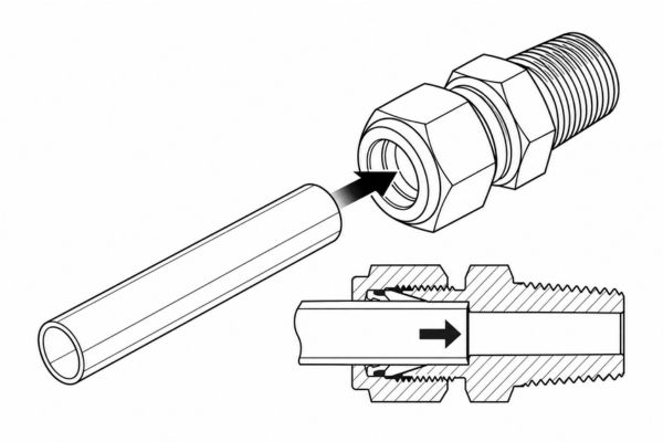
Step 2: Insert the tube until it bottoms out
Push the tube into the fitting until its end rests firmly against the internal shoulder of the fitting body. Keep the tube aligned and in position while beginning the assembly.
Step 3: Tighten the nut by hand
While keeping the tube fully inserted, turn the nut by hand until it reaches the manufacturer’s specified finger-tight starting position.
The nut should turn smoothly at the beginning. If it binds immediately, stop and check alignment, thread condition, and component compatibility. Forcing a cross-threaded nut can damage the fitting before the ferrules are properly installed.
Step 4: Mark the starting position
Use a marker to make a reference mark on the nut.
This mark makes it easier to see how far the nut has turned after the finger-tight position. The reference mark is useful only if the starting position is correct and the fitting body remains stationary during tightening.
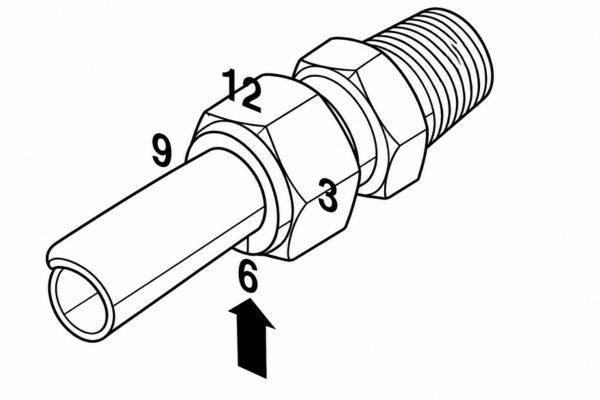
Step 5: Hold the body and tighten the nut
Use one wrench or a suitable fixture to hold the fitting body. Use the second wrench to turn the nut according to the manufacturer’s instructions.
Do not allow the body to rotate unnecessarily. If the body turns, the installer may lose track of the nut’s rotation and may also apply unwanted movement to a connected component.
| Tube outside diameter | Rotation after finger-tight | Mark position |
| 1/16, 1/8, and 3/16 in.; 2, 3, and 4 mm | 3/4 turn | From 6 o’clock to 3 o’clock |
| 1/4 through 1 in.; 6 through 25 mm | 1 1/4 turns | From 6 o’clock to 9 o’clock |
What happens if the fitting is under-tightened?
If the nut has not completed the required assembly movement, the ferrules may not be positioned or deformed as intended. The connection may leak or fail to achieve the intended tube grip.
A nut that feels tight is not, by itself, proof that the correct installation procedure has been completed. Use the specified starting point and tightening method.
Can you over-tighten a tube fitting?
Yes. Turning the nut beyond the specified position can damage components or make later disassembly and reassembly more difficult. “Tighter” should not be used as a substitute for the manufacturer’s installation instruction.
If you suspect the fitting has been over-tightened, do not assume a gap gauge can determine whether the assembly is acceptable. Assess it according to the manufacturer’s instructions and the site’s inspection procedure.
How to Check the Fitting After Installation
A completed connection should be checked against the applicable installation and inspection procedure before the system returns to service.
Check the installation marks
Compare the nut’s final position with the required rotation from the finger-tight starting point. Confirm that the fitting body did not rotate during the operation.
A mark is a useful installation record, but it does not prove that the tube was suitable, the ferrules were correctly oriented, or the tube remained bottomed during assembly.
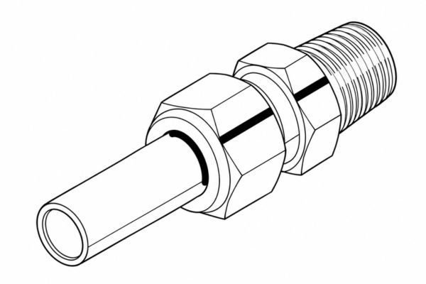
Use the correct gap inspection gauge
If the fitting manufacturer provides a gap inspection gauge for the exact fitting and initial assembly method, use it according to that manufacturer’s instructions.
A gap inspection gauge checks only the condition defined by its manufacturer. It does not verify tube material, wall thickness, ferrule orientation, fluid compatibility, or whether the fitting has been over-tightened.
Carry out the specified system check
After assembly, inspect and test the system using the approved procedure for the equipment and application. The test method, medium, pressure, and acceptance criteria must come from the applicable system requirements.
If a leak is found, isolate and depressurize the system before investigating. Do not place your hand near a suspected high-pressure leak, and do not tighten a fitting while the system is pressurized.
How to Disassemble and Reassemble a Tube Fitting
A previously assembled fitting should not automatically be tightened using the same turn count as a new fitting. Its ferrules have already been set onto the tube, so the reassembly procedure is different.
Step 1: Isolate and depressurize the system
Before loosening the nut, shut down and isolate the relevant section of the system. Safely release stored pressure and deal with the contained fluid according to the site procedure.
Do not loosen a fitting nut or plug as a method of releasing system pressure.
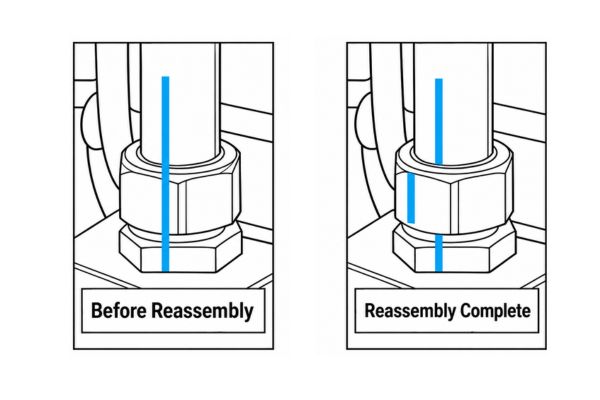
Step 2: Mark the original position
Before disassembly:
- Marking the tube at the back of the nut.
- Drawing an alignment mark across the nut and fitting body.
These marks provide a reference for returning the nut to its previous assembled position.
Step 3: Inspect the components
After disassembly, check the tube, ferrules, nut, and fitting body for damage, contamination, corrosion, or other conditions that may prevent reuse.
Follow the manufacturer’s criteria for reuse. A fitting should not be returned to service merely because the nut can be threaded back onto the body. If components are damaged or their history is uncertain, determine the correct replacement method with the manufacturer.
Step 4: Reinsert and tighten according to the product instructions
Reassembly procedures vary by fitting design. After inspecting the components, follow the manufacturer’s instructions for seating the tube and returning the nut to the correct position. Do not apply the full initial-installation turn count to previously set ferrules unless the manufacturer specifically instructs you to do so.
Do not use a first-installation turn count for every reassembly
A full first-installation turn count is intended to set new ferrules. Applying it again to ferrules that are already set can result in excessive tightening.
If the original position was not marked, consult the product’s reassembly instructions before proceeding. Do not guess the previous position from the number of visible threads.
How Close Can a Tube Bend Be to the Fitting?
A fitting needs a suitable straight section of tube at the connection. If the bend begins too close to the fitting, the area under the ferrules may be distorted or the tube may enter the body at an angle.
Those dimensions are useful only when the fitting design, size, measurement method, and bending conditions match the source. For another series, use that manufacturer’s bend and straight-length requirements.
When laying out a tube assembly:
- Make the bend before completing the fitting installation.
- Leave the required straight section at the tube end.
- Keep the tube aligned with the fitting bore.
- Avoid forcing the tube sideways to make the nut engage.
- Support the tube according to the system design, especially where vibration or movement is present.
- Check that the bend does not interfere with wrench access or future maintenance.
If there is not enough room for a suitable straight section, revise the routing or consider an appropriate elbow fitting. Confirm the alternative against the system’s pressure, flow, and connection requirements.
How to Install a Tube Fitting with an NPT Thread
Some tube fittings have a double-ferrule tube connection on one end and a male NPT thread on the other. These are two different connection interfaces and must be assembled according to their respective instructions.
| Connection end | How it is assembled | Use of thread sealant |
| Double-ferrule tube end | Tube is inserted into the fitting; the nut and ferrules are assembled according to the fitting instructions | Do not apply pipe-thread sealant to the ferrules or tube sealing area |
| Male NPT end | Tapered male pipe thread is assembled into a compatible female pipe-thread port | Use a suitable sealant when required by the connection and manufacturer instructions |
Check the thread before assembly
Confirm that the port and fitting have compatible thread types and sizes. NPT, BSPT, and other tapered threads may appear similar, but appearance alone does not establish compatibility.
Inspect the threads for damage, dirt, and contamination. Start the fitting by hand to reduce the risk of cross-threading. If it does not engage smoothly, stop and identify the problem.
Apply suitable sealant to the NPT end
Where PTFE tape or another sealant is specified, select a product compatible with the system fluid, temperature, and application.
Follow the sealant and fitting manufacturer’s directions for application and tightening. Keep tape or sealant away from the opening so loose material does not enter the system.
Tighten without relying only on exposed threads
Use the applicable manufacturer procedure to tighten the NPT connection. Do not use the number of exposed threads as the sole acceptance criterion for every fitting and port combination.
Avoid excessive tightening. If the connection needs a particular orientation, follow the component manufacturer’s instructions; do not assume that backing off a tightened tapered thread will preserve the intended seal.
Common Tube Fitting Installation Mistakes
| Mistake | Why it matters | Better practice |
| Tube is not fully inserted | Ferrules may be set while the tube is in the wrong position | Bottom the tube against the shoulder and hold it there during assembly |
| Tube surface is scratched or dented | Damage in the ferrule contact area may affect sealing | Inspect the tube and use an acceptable, undamaged section |
| Tube size is correct but wall or hardness is unsuitable | The ferrules and tube may not work together as designed | Check the complete tube specification against the fitting requirements |
| Ferrules are missing or reversed | The assembly may not form the intended grip or seal | Check the manufacturer’s component arrangement |
| Parts from different brands are mixed | Similar-looking components may have different dimensions or profiles | Use approved matching components |
| Nut rotation is estimated without a starting mark | It becomes difficult to confirm the prescribed pull-up | Mark the nut at the correct starting position |
| Fitting body rotates during tightening | Nut rotation becomes difficult to measure and connected parts may move | Hold the body steady while turning the nut |
| A first-installation turn count is used during reassembly | Previously set ferrules may be over-tightened | Follow the manufacturer’s reassembly method |
| A gap gauge is used on a reassembled fitting | The gauge may not provide a valid result | Use the specified reassembly inspection method |
| The fitting is adjusted while pressurized | Fluid can escape under pressure | Isolate and depressurize before adjustment |
| Pipe-thread tape is placed on the ferrule end | Tape can interfere with assembly or contaminate the system | Use sealant only where the connection design calls for it |
Frequently Asked Questions
Should the tube be fully inserted into a double-ferrule fitting?
Yes. Insert the tube until it rests firmly against the fitting body shoulder and keep it in position while starting assembly. Follow the specific instructions for the fitting you are using.
How many turns does a double-ferrule fitting need?
The required rotation depends on the manufacturer, product series, tube size, and installation method.
Can I use ferrules and nuts from different manufacturers?
Do not mix or interchange components unless the relevant manufacturer explicitly approves the combination. Similar-looking parts can have different profiles and tolerances.
Can I reuse a double-ferrule fitting?
Some fitting designs permit disassembly and reassembly when the components remain in acceptable condition. Reuse depends on the product, component condition, service history, and manufacturer’s instructions. Always depressurize before disassembly.
Do I need PTFE tape on the ferrules?
No pipe-thread tape should be applied to the ferrules or tube sealing area. A separate NPT pipe-thread end may require a suitable thread sealant, depending on the connection and manufacturer’s instructions.