Hydraulic tube wall thickness and hardness must be checked against the exact tube material, outside diameter, fitting system, and application—not against a universal chart. A tube can have the expected nominal OD yet still be unsuitable because its wall, material condition, hardness, ovality, or surface prevents the flare or cutting ring from forming the intended connection. The practical consequence may be assembly damage, poor sealing, reduced retention, or an unapproved pressure boundary.
The Fitting System Defines the Tube Acceptance Boundary
Tube selection begins with the complete connection design. A flare fitting forms and clamps a prepared tube end against a mating seat, while a cutting-ring or bite-type system depends on controlled interaction between the ring and the tube outside surface. Because those mechanisms differ, a tube accepted for one product family is not automatically accepted for another.

Selection is system-specific
The relevant manufacturer documentation may limit tube OD, wall range, material grade or family, condition, hardness, surface quality, preparation, and assembly method. Those limits belong to the identified fitting series and revision. A table for a similar-looking fitting, another material, or another manufacturer’s product cannot be copied into the purchase specification without approved engineering evidence.
Application requirements also remain separate. The fluid, temperature, pressure cycles, vibration, routing, corrosion exposure, fabrication method, and governing equipment rules can narrow the permitted tube even when the fitting catalog lists it as dimensionally usable. The lowest-rated or least-suitable part of the assembled connection controls the result.
Tube approval is not fitting approval
A material certificate can support the tube’s identity and reported properties, but it does not prove that a selected fitting will assemble or perform correctly. Conversely, a fitting catalog can state its tube requirements, but it does not prove that a delivered tube lot meets them. Buyers need evidence for both sides and a controlled decision linking the exact tube description to the exact fitting system.
Outside Diameter and Wall Thickness Do Different Jobs
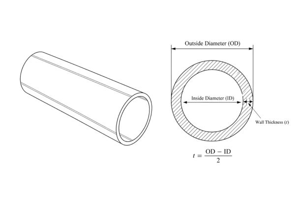
Tube OD controls how the tube enters and contacts the fitting, while wall thickness influences the tube’s resistance to forming, local collapse, and application loading. Neither value should be considered alone. Nominal size is only a starting label; the purchase requirement needs the applicable tolerances and measurement method.
OD affects fit and sealing contact
Many tube fittings interact with the outside surface, so OD, ovality, surface finish, weld condition, and local damage can affect assembly. A tube that is oversize or out of round may not enter the nut, ring, sleeve, or body correctly. An undersize or locally flattened surface may not provide the contact assumed by the fitting design, even if a single caliper reading appears acceptable.
Measure OD in multiple directions and at controlled locations away from damaged cut ends. Record the instrument, calibration status, tube orientation, location, and readings rather than only a rounded average. Compare the result with the approved tube and fitting requirements, not with a remembered nominal value.
Wall thickness changes forming response
In a flare system, the wall must support the specified preparation and form the flare without unacceptable thinning, cracking, eccentricity, or geometry. In a cutting-ring system, an excessively compliant wall may deform under assembly, while a wall outside the approved range can change how the ring engages or how tools and sleeves fit. The exact consequence and acceptance criteria depend on the specific system.
Wall thickness should be checked around the circumference where required, because one reading cannot reveal eccentricity. Buyers should distinguish nominal wall from minimum actual wall, measured wall, and any design value used in an application calculation. Do not assume that a thicker wall always increases the approved pressure capability; the fitting, tube, assembly, and application each impose limits.
Material Condition and Hardness Affect Assembly Behavior
Hardness is relevant because the tube must deform or accept engagement in the way the fitting design expects. It is not a stand-alone quality score, and a higher value is not automatically better. Material grade, heat-treatment or temper condition, manufacturing route, and surface condition must be considered with the measured property.
Grade names are not enough
Two tubes described by a broad alloy family can arrive in different material conditions. Annealing, cold work, welding and drawing, heat treatment, and fabrication after delivery can change hardness or forming response. A certificate should identify the lot, material specification, grade, condition, test results where required, and the document revision or purchase requirement used for comparison.
Hardness also needs a defined method, scale, location, and sampling plan. A value copied from a supplier brochure does not establish the delivered lot, and one indentation may not represent a long coil or every tube in a bundle. If the fitting manufacturer states a maximum or acceptable condition, use that exact requirement and test basis rather than converting scales casually.
Surface and geometry remain independent
A hardness result within the permitted range cannot approve scratches, seams, flat spots, coating buildup, burrs, or ovality. These features can affect sealing and ring engagement even when material chemistry and hardness are correct. Incoming inspection should therefore keep identity, geometry, surface, and mechanical-property evidence as separate checks.
Drawings, Certificates, and Manufacturer Data Have Separate Roles
No single document normally answers the whole selection question. A controlled assembly drawing identifies what the equipment design calls for, a tube certificate describes the delivered material evidence, and fitting-manufacturer documentation defines permitted combinations and assembly requirements. The review must reconcile them at their current revisions.
Evidence hierarchy
Use the equipment’s controlled specification to establish the intended tube OD, wall, material, connection type, environment, and any additional acceptance criteria. Use current fitting-system documentation to confirm permitted tube characteristics and the exact tooling or preparation needed. Use purchase records, markings, certificates, and inspection results to show that the delivered tube corresponds to those requirements.
The core records are:
- Controlled equipment drawing, bill of material, and connection specification with revision status
- Exact fitting manufacturer, series, material, size, and current tube-selection instructions
- Tube purchase description, material specification, grade, condition, OD, wall, length form, and surface requirements
- Lot-linked material certificate and any required hardness or mechanical-property results
- Incoming OD, wall, ovality, surface, and marking inspection records
- Approved fabrication and assembly procedures for flaring, cutting-ring assembly, bending, cleaning, and inspection
Conflicts must be resolved before buying or releasing tube to production. An older drawing, certificate without lot linkage, or catalog excerpt without a product series is evidence of a gap, not permission to select the closest available material.
Compare What Each Record Can Establish
The comparison below helps prevent a common purchasing error: asking one record to prove something outside its purpose. The “cannot establish alone” column is as important as the evidence column.
| Record or check | What it can establish | What it cannot establish alone |
| Equipment drawing/specification | Intended OD, wall, material, fitting system, application and revision | Delivered lot conformity or current fitting approval |
| Fitting manufacturer tube table | Permitted tube range and conditions for the named series | Identity or condition of received tube |
| Material certificate | Reported grade, condition, lot and tested properties when included | OD, ovality, surface condition, assembly quality or final compatibility |
| Incoming dimensional inspection | Actual sampled OD, wall and geometry at recorded locations | Chemistry, lot-wide conformity or pressure approval |
| Hardness test report | Result by stated method, scale, location and sample | Flare quality, surface suitability or fitting performance |
| Trial assembly inspection | Whether a controlled sample meets the specified assembly criteria | Universal approval for other lots, tools, sizes or applications |
Follow a Repeatable Tube Selection Workflow
A reliable workflow starts before a request for quotation. It converts the application and fitting decision into a tube purchase specification that can be quoted, inspected, and repeated. Each stage should preserve the source and revision of the requirement.
From connection callout to purchase order
- Identify the equipment, circuit, application conditions, and governing drawing revision.
- Confirm the fitting type, manufacturer, series, material, size, and sealing mechanism.
- Obtain the current tube requirements and assembly instructions for that exact system.
- Define tube OD, wall, material specification, grade, condition, manufacturing route, surface, and tolerances as applicable.
- Define required certificates, lot traceability, markings, sampling, measurement methods, and acceptance records.
- Review bending, cutting, flaring, ring assembly, cleaning, and inspection processes that may change or damage the tube.
- Resolve every conflict, then release a controlled purchase description and retain the approval basis.
Do not treat a supplier’s ability to quote a nominal size as technical acceptance. The quoted description should repeat or reference the controlled requirements clearly enough that substitutions, alternative conditions, and missing evidence are visible before the order is placed.
Hypothetical Review of Two Tube Offers
Consider an explicitly hypothetical project that calls for a documented tube connection, but the purchasing file contains only a nominal OD and material family. Offer A includes a lot-linked certificate and a wall description, yet does not identify the material condition. Offer B identifies a condition and nominal wall, but its certificate is not tied to the proposed delivery lot. Neither offer includes confirmation against the selected fitting series.
Evidence-based disposition
The buyer cannot choose A or B on price, certificate length, or nominal size alone. The team first retrieves the current equipment drawing and fitting-system tube table, then adds the required condition, hardness evidence if specified, OD and wall tolerances, surface requirements, and traceability to the purchase description. Each bidder must respond to the same controlled requirement.
If a supplier proposes an alternative tube, the deviation should identify every changed field and include the evidence needed for technical review. Approval of that hypothetical deviation would apply only to the documented tube, fitting series, process, and application. It would not create a general permission to use the alternative elsewhere.
Avoid Common Shortcuts and Close the Open Items
The most damaging shortcuts are assuming that nominal OD proves fit, that thicker wall is safer, or that a material grade automatically establishes hardness and condition. Another mistake is using a material certificate as final assembly approval. These shortcuts hide the actual interface between tube behavior and fitting design.
Reasons to stop and request review
Stop the selection when the fitting series is unknown, current tube limits are unavailable, documents conflict, or a proposed material condition falls outside the approved data. Also escalate unexplained ovality, visible seams or surface defects, missing lot linkage, uncertain hardness method, and fabrication processes that may alter the tube. Do not solve uncertainty by forcing a tube into a fitting or by changing assembly practice without approval.
Before release, confirm:
- Exact fitting series, size, material, and current document revision
- Tube OD, wall, material grade, condition, manufacturing route, and applicable tolerances
- Required hardness property, test method, scale, sample location, and acceptance source when specified
- Surface, ovality, weld, burr, straightness, and end-preparation requirements relevant to the system
- Application fluid, temperature, pressure cycles, vibration, corrosion, routing, and fabrication constraints
- Lot traceability, certificates, incoming checks, deviation control, and assembly inspection records
This checklist should end with an approval owner and document reference. An unanswered field that affects forming, sealing, retention, or pressure integrity keeps the tube selection open.
Conclusion
Hydraulic tube wall thickness and hardness are connection-specific selection inputs, not universal quality targets. First confirm the exact flare or cutting-ring system, then use its current documentation to define acceptable tube OD, wall, material, condition, hardness, surface, and preparation. The equipment drawing establishes design intent; the tube certificate supports lot identity and reported properties; dimensional and surface inspections confirm sampled physical condition. None of those records alone proves the complete assembly. Resolve conflicting revisions, require traceable evidence, and document any deviation before purchase or fabrication. A thicker wall or harder tube is not automatically safer, and nominal OD does not guarantee fit. The next action is to issue one controlled tube specification linked to the approved fitting system and application.
Frequently Asked Questions
Can the same tube be used with flare and cutting-ring fittings?
Only when the current requirements for both specific fitting systems approve that tube. Their forming and engagement mechanisms differ, so a tube accepted for one series cannot be assumed suitable for the other.
Does a material certificate prove tube hardness is acceptable?
Only if the certificate is traceable to the delivered lot and reports the required property by the specified method. It still does not prove OD, wall, ovality, surface condition, or successful assembly.
Is thicker hydraulic tube always able to handle more pressure?
No, a thicker wall does not automatically raise the approved assembly pressure. Fitting capacity, tube material, tolerances, connection design, fabrication, and application conditions all affect the allowable result.
Should buyers specify a universal maximum hardness?
No, buyers should use the hardness or material-condition requirement for the exact fitting system and tube specification. A universal limit can be wrong for another alloy, condition, test method, or connection design.
What should happen when the tube and fitting documents disagree?
Pause purchasing or assembly and send the conflict for controlled technical review. Record the affected revisions and obtain an approved resolution instead of choosing the less restrictive value.