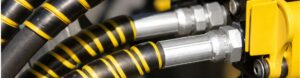
Hydraulic systems are essential power transmission networks that drive critical machinery across numerous industries. At the heart of these systems lie the flexible hose assemblies, acting as vital conduits for pressurized fluid. The integrity and reliability of a hydraulic circuit are directly dependent on the proper selection and compatibility of its hoses and fittings. Incompatible components introduce significant risks, leading to costly downtime, reduced productivity, severe safety hazards for personnel, and potential environmental damage from leaks and spills. This article provides a comprehensive guide to understanding and mastering hydraulic fitting and hydraulic hose compatibility, empowering professionals to select, assemble, and maintain these critical components effectively and prevent system failures.
The Cornerstone of Compatibility: The STAMPED Method
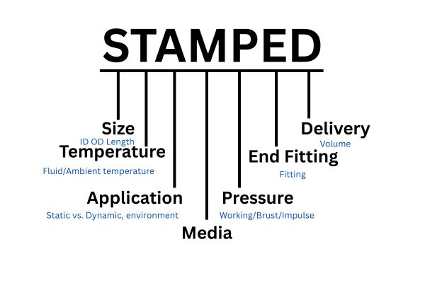
The STAMPED acronym represents a comprehensive checklist encompassing the key technical factors that must be considered when selecting and matching hydraulic hoses and fittings: Size, Temperature, Application, Media, Pressure, Ends, and Delivery (Volume). This systematic approach helps prevent oversights that can lead to incompatibility issues and premature failure.
Conceptual diagram illustrating the interconnected factors of the STAMPED method for hydraulic hose and fitting selection.
Let’s break down each factor:
Size
Accurate sizing is paramount for both functional performance and physical compatibility.
- Inside Diameter (ID): The hose’s ID must be correctly matched to the required flow rate of the hydraulic fluid. An undersized hose will restrict flow, causing pressure drops, generating excessive heat, and potentially cavitating pumps. An oversized hose adds unnecessary weight and cost.
- Outside Diameter (OD) and Length: The OD and length are critical for proper routing and installation. Incorrect length can lead to excessive slack (potential for abrasion or kinking) or insufficient slack (putting components under tension during movement or thermal expansion/contraction).
- Fitting Size: The fitting’s size must be compatible with the selected hose’s ID and the size of the port it will connect to in the system (e.g., pump, valve, cylinder).
Temperature
Both the hydraulic fluid’s temperature and the ambient environmental temperature surrounding the hose assembly must be within the specified operating range of both the hose and the fittings (including any O-rings or seals).
- Fluid Temperature: High fluid temperatures can cause the hose’s inner tube and reinforcement to degrade rapidly, leading to hardening, cracking, or reduced pressure capacity. Low fluid temperatures can make the hose stiff and brittle, susceptible to damage from flexing or vibration.
- Ambient Temperature: External heat sources (like hot engine components or furnaces) or cold environments can affect the hose cover and reinforcement layers. Prolonged exposure to temperatures outside the rated range degrades materials. Consider using heat shields or hoses with specialized temperature ratings where necessary.
Application
Understanding the specific conditions and demands of the application is vital for selecting components robust enough to withstand the operating environment.
- Static vs. Dynamic: Is the hose in a fixed position (static) or subjected to constant movement, flexing, or vibration (dynamic)? Dynamic applications, especially those with frequent pressure cycles (impulse), require hoses and fittings designed for high cycle life (e.g., multi-spiral hoses like SAE 100R12 or ISO 18752 standards).
- Environmental Exposure: Will the hose be exposed to UV radiation, ozone, chemicals, saltwater, abrasive particles, or extreme weather? The outer cover material must be selected to resist these elements.
- Routing Requirements: Considerations include minimum bend radius, the need to avoid twisting, and the potential for abrasion against other components or surfaces. Proper routing (covered in subsequent sections) is heavily influenced by the application.
- Regulatory Requirements: Some applications (e.g., mining) may require hoses that meet specific standards like MSHA flame resistance.
Media (Material)
The chemical composition of the hydraulic fluid and any external media the hose assembly will contact dictates the necessary material compatibility for all components.
- Fluid Compatibility: The hose’s inner tube and any internal seals (like O-rings in ORFS fittings) must be chemically compatible with the hydraulic fluid. Incompatibility can lead to swelling, shrinkage, hardening, softening, or chemical breakdown of the material, resulting in flow restriction, leaks, loss of pressure rating, and contamination of the hydraulic system.
- External Media: The hose cover and fitting materials (e.g., plating) must be resistant to external chemicals, oils, solvents, or corrosive substances present in the operating environment.
Pressure
This is one of the most critical factors. Both the hose and the fittings must have a maximum Working Pressure rating that meets or exceeds the maximum peak pressure the system will experience, including any pressure spikes or surges that occur during operation.
- Working Pressure: The maximum continuous pressure the component is designed to safely handle.
- Burst Pressure: The theoretical pressure at which the component is expected to fail (typically 4:1 safety factor for standard hydraulic hoses per standards like SAE J517).
- Impulse Pressure: The ability of the hose assembly to withstand rapid, repetitive pressure cycles. Hoses designed for high impulse applications (e.g., SAE 100R2, 100R12, 100R15, ISO 18752 classes) are reinforced to handle the fatiguing effects of these cycles.
- Relevant Standards: SAE J517 (for hose types and basic pressure ratings), ISO 18752 (performance-based constant pressure ratings for hoses), SAE J514, SAE J1453, ISO 8434 series (for fitting pressure ratings). Always use the lowest rated component in the assembly as the limiting factor for the entire hose assembly’s working pressure.
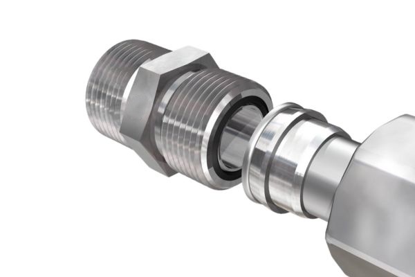
Ends
Selecting the correct fitting type and size for both ends of the hose assembly, and ensuring their mechanical compatibility with the ports they connect to, is fundamental for a leak-free connection.
- Fitting Type and Standard: Common types like JIC (37° flare, SAE J514 / ISO 8434-2), ORFS (O-Ring Face Seal, SAE J1453 / ISO 8434-3), NPTF (National Pipe Tapered Fuel), and DIN/Metric (ISO 8434-1 etc.) use different sealing mechanisms and thread types. Mixing incompatible types or standards (e.g., attempting to mate a JIC male with an NPTF female) will result in leaks or damage.
- Thread Compatibility: Even within the same family, thread pitch and size must match precisely.
- Hose-to-Fitting Compatibility: Crucially, the specific fitting series must be approved by the hose manufacturer for use with the selected hose type and size. Manufacturers design their hoses and fittings as integrated systems, and their crimp specifications are validated for specific hose-fitting combinations. Mixing brands or using unapproved combinations is a primary cause of fitting blow-offs under pressure.
- Relevant Standards: SAE J514, SAE J1453, ISO 8434 series provide specifications for these end connections.
Delivery (Volume)
This factor focuses on the required flow rate (volume per unit time) of the hydraulic fluid, which directly influences the necessary Inside Diameter (ID) of the hose, reiterating the importance of the ‘Size’ factor from a flow perspective.
- Flow Rate: System designers calculate the required fluid velocity and flow rate based on cylinder speed, motor RPM, etc. This dictates the required hose ID to maintain efficient flow and avoid excessive velocity, which causes turbulence, heat, and pressure drops.
- Undersized hoses lead to increased fluid velocity, resulting in significant pressure losses and heat generation due to friction. This reduces system efficiency and can damage components over time.
Applying the STAMPED method systematically for every hose assembly ensures that all critical factors influencing compatibility and performance are addressed, significantly reducing the risk of premature failure.
The High Cost of Incompatibility: Consequences of Mismatch
Ignoring the critical principles of matching hoses and fittings, or failing to adhere to proper assembly and installation techniques, inevitably leads to severe consequences. These range from minor annoyances to catastrophic failures, impacting system performance, costs, and, most importantly, safety.
System Failures and Downtime
Incompatible or improperly installed components are direct pathways to system breakdown.
Leaks
- Causes: Mismatched thread types or sealing surfaces (e.g., NPTF attempting to seal on a JIC port), damaged or missing O-rings/seals (especially in ORFS, ORB, or metric fittings), improper torque (under or over-tightening), excessive vibration or flexing fatiguing the connection, material degradation (hose or seal), internal damage from contamination.
- Impact:
- Loss of hydraulic pressure, leading to reduced system speed, force, and overall performance.
- Increased operating costs due to fluid loss and replenishment.
- Potential for environmental contamination and associated fines.
- Introduction of external contaminants into the system if the leak occurs during vacuum conditions (e.g., suction lines).
Hose Bursts:
- Causes: Exceeding the assembly’s maximum working pressure (including pressure spikes), using a hose or fitting with an insufficient pressure rating for the application, using an incompatible hose/fitting combination that compromises crimp integrity, violating the hose’s minimum bend radius (damaging reinforcement), severe abrasion or external damage compromising the reinforcement, chemical degradation of hose materials, assembly defects (incorrect crimp diameter, improperly seated fitting).
- Impact:
- Catastrophic failure of the hose assembly.
- Sudden loss of system pressure, rendering the equipment inoperable.
- Potential for significant equipment damage from sudden loss of function (e.g., dropping a load).
- Severe and costly unscheduled downtime for repair and cleanup.
Fitting Blow-offs/Crimp Failures:
- Causes: Using a hose and fitting combination that is not approved by the hose manufacturer, incorrect crimping procedure (wrong die, incorrect crimp diameter), exceeding the assembly’s temperature rating (weakening materials), exceeding the pressure rating.
- Impact: Similar to a hose burst, resulting in catastrophic fluid release, total system shutdown, equipment damage, and significant safety hazards. This is a direct failure of the mechanical connection between the hose and the fitting.

Contamination and Component Damage
Incompatibility doesn’t just cause leaks; it can internally degrade the system.
- Internal Degradation from Incompatible Media: If the hose inner tube or seals are not compatible with the hydraulic fluid, the material can swell, soften, harden, or chemically break down. This generates particles that contaminate the hydraulic fluid.
- External Contamination Ingress: Leaks allow dirt, moisture, and debris from the environment to be drawn into the system, especially in low-pressure or vacuum lines (like suction lines).
- Accelerated Wear on System Components: Contaminated fluid circulating throughout the system causes accelerated wear on expensive and critical components like pumps, valves, and cylinders. Fine particles act as abrasives, damaging precision surfaces and seals. This reduces component lifespan and necessitates premature replacement or costly repairs.
Safety Hazards
The consequences of improper matching extend beyond equipment damage to pose serious risks to personnel.
- High-Pressure Fluid Injection: Even a tiny pinhole leak in a hydraulic line operating at high pressure can eject fluid with enough force to penetrate skin. Hydraulic fluid injection injuries are extremely dangerous; the fluid can cause severe tissue damage and necrosis, often requiring amputation if not treated immediately and correctly by specialists. This risk is often underestimated but can be life-altering or fatal.
- Slips, Trips, and Falls: Spilled hydraulic fluid creates hazardous, slippery surfaces in the work area.
- Fire Hazards: Hydraulic fluids, especially petroleum-based types, are often flammable. Leaks onto hot surfaces (like engines or exhaust components) can ignite, causing fires that endanger personnel and equipment.
- Injury from Hose Burst or Fitting Blow-off: A hose bursting or a fitting blowing off under thousands of PSI pressure releases stored energy violently. The whipping action of a failed hose or the projection of a fitting can cause blunt force trauma, lacerations, and burns from escaping hot fluid.
Best Practices for Selection, Assembly, and Installation of Hydraulic Hose Assemblies
Selecting the right hose and fittings is the first critical step, but proper assembly and installation are equally vital to prevent premature failure and ensure system reliability. Even perfectly matched components can fail if handled incorrectly during these stages.
Component Selection
As discussed in the previous section, systematically applying the STAMPED method for every hose assembly requirement is fundamental. Always consult current manufacturer catalogs and technical data for specific hose and fitting specifications, pressure ratings, temperature limits, minimum bend radii, and, crucially, compatibility charts. Insisting on using hoses and fittings from the same manufacturer is the most reliable way to ensure validated compatibility and access accurate crimping specifications, minimizing the risk of fitting blow-offs.
Proper Assembly Techniques
The assembly process itself, particularly cutting and crimping, requires precision and strict adherence to manufacturer guidelines.
- Cleanliness: Absolute cleanliness is paramount. Any dirt, debris, or contamination introduced during assembly will immediately enter the hydraulic system, potentially damaging pumps, valves, and cylinders. Ensure components, tools, and the work area are clean. Cap or plug hose ends immediately after cutting.
- Cutting the Hose: Hoses must be cut square and clean using the recommended tool (e.g., a chop saw with a fine-toothed blade for wire-reinforced hose, a sharp knife for thermoplastic). Improper cutting can distort the hose end, making fitting insertion difficult and potentially affecting crimp quality.
- Fitting Insertion: Push or thread the fitting insert into the hose end squarely, ensuring it is fully seated against the internal stop according to the manufacturer’s instructions.
- Crimping: This is arguably the most critical step. Always use the crimping equipment, dies, and specifications provided by the hose and fitting manufacturer for that specific hose and fitting combination.
- Die Selection: Select the correct crimp die based on the hose type, size, and fitting series.
- Crimp Diameter: The final crimp diameter is the most critical parameter. Measure the crimped diameter at multiple points along the crimped shell using calipers. It must fall within the narrow tolerance range specified by the manufacturer. Under-crimping results in insufficient retention strength, leading to fitting blow-off. Over-crimping can damage the hose reinforcement or fitting, restricting flow and potentially causing failure.
- Visual Inspection: After crimping, visually inspect the assembly. The crimp shell should be evenly formed without cracks, splits, or excessive distortion. Ensure the hose is properly seated against the fitting collar.
- Threading: For threaded fittings, use appropriate torque values specified by the manufacturer. Over-torquing can damage threads and fitting bodies, especially NPTF fittings which rely on thread deformation. Use recommended thread sealant sparingly on tapered threads if required, ensuring it is compatible with the hydraulic fluid. For fittings using O-rings (like ORFS or ORB), ensure the O-ring is present, undamaged, correctly seated, and made of a material compatible with the fluid and temperature.
Effective Routing and Installation
Proper hose routing and installation significantly impact the assembly’s lifespan and system safety.
- Correct Length: Determine the optimal hose length by considering the distance between ports at all points in the equipment’s cycle of motion. Allow enough slack to accommodate movement, vibration, thermal expansion/contraction, and pressure changes (which can cause slight length changes). Too little slack puts components under tension; too much slack creates a hazard for kinking or abrasion.
- Minimum Bend Radius: Strictly adhere to the manufacturer’s specified minimum bend radius for the chosen hose type and size.
- Importance: Bending a hose tighter than its minimum radius damages the reinforcement layers, constricts the inner tube (reducing flow), and creates points of high stress, leading to kinking and premature failure.
- How to find it: This value is listed in the hose manufacturer’s technical specifications or catalog for each specific hose type and size.
- Consequences: Violating the minimum bend radius significantly reduces the hose’s pressure capacity and impulse life, making it highly susceptible to bursting or kinking under pressure.
- Avoiding Twisting: Never install a hose in a twisted condition. Twisting a hose introduces torque that fights against the hose’s natural tendency to relax, severely weakening the reinforcement and leading to premature failure, often near the fittings. Use the hose layline (the stripe or printing along the hose cover) as a visual guide – it should remain straight along the entire length of the installed hose, not spiral.
- Using Clamps and Supports: Utilize clamps, brackets, and supports strategically to secure hoses, prevent excessive movement or vibration, manage the hose’s weight in long runs, and guide the hose along a desired path, helping maintain the minimum bend radius.
- Avoiding Abrasion Points: Route hoses away from sharp edges, corners, moving parts, and surfaces they could rub against. Even minor rubbing over time can wear through the tough outer cover, exposing and eventually damaging the critical reinforcement layers. Use protective sleeving or guards in unavoidable abrasion areas.
- Using Adapters and Elbows: Employ hydraulic adapters and elbows where necessary to achieve correct alignment between the hose and the port, minimize sharp bends, and facilitate proper routing while respecting the minimum bend radius.
By following these best practices, you build assemblies that are not only correctly matched but also physically capable of withstanding the demands of the application over their intended lifespan.
Troubleshooting Common Hose and Fitting Issues
Even with proper selection and assembly, issues can arise in hydraulic hose assemblies. Effective troubleshooting involves recognizing symptoms, identifying probable causes, and implementing appropriate remedies.
Identifying Problems
Regular visual inspection is key. Look for:
- Visible leaks at fittings or along the hose body.
- Bubbling, blistering, or cracking of the hose cover.
- Abrasion marks or cuts on the hose cover.
- Kinked or flattened sections of hose.
- Hose appears twisted (check the layline).
- Excessive stiffness or hardening of the hose material.
- Corrosion or damage on fittings.
- Loose fittings.
- Unusual noises (hissing, gurgling).
- Changes in system performance (sluggishness, overheating).
Step-by-Step Diagnosis
- Safety First: De-energize and depressurize the hydraulic system before inspecting or working on any components. Wear appropriate PPE.
- Identify the Symptom: Clearly define what is happening (e.g., leak, burst, abnormal noise).
- Analyze the Location: Note exactly where the problem is occurring (e.g., at the fitting crimp, mid-hose, near a bend).
- Review STAMPED: Revisit the application’s requirements and compare them against the specifications of the installed hose assembly. Was the initial selection correct? Consider Size (flow), Temperature (fluid/ambient), Application (dynamic/static, environment), Media (fluid compatibility), Pressure (peak pressure, impulse), Ends (fitting type/crimp), Delivery (flow/ID).
- Inspect the Assembly and Routing: Examine the failed assembly and its routing path for signs of improper installation (incorrect crimp, twisted hose, violation of bend radius, abrasion points).
Conclusion
Prioritizing correct matching and installation is a vital investment that ensures reliable system operation, minimizes costly downtime and repairs, protects the environment, and, most importantly, safeguards personnel from hazardous high-pressure fluid incidents. If you need high-quality hydraulic hose and fittings, contact Topa, we can provide!
Bibliography
- International Organization for Standardization. (n.d.). ISO 1436: Rubber hoses, rubber covers and hose assemblies—Wire-braid reinforced hydraulic type—Specification.
- Jason Industrial. (n.d.). Using the S.T.A.M.P.E.D. process to choose hydraulic hoses.
- Marshall. (n.d.). 10 common hydraulic hose failures & how to solve them.
- SAE International. (n.d.). SAE J514: Hydraulic tube fittings. Retrieved from SAE International website.
- Weekly Safety Meeting. (n.d.). Dangers of hydraulic hoses.
FAQ
What is the STAMPED method and why is it essential for selecting hydraulic hoses and fittings?
The STAMPED method helps ensure correct hose and fitting selection by systematically evaluating Size, Temperature, Application, Media, Pressure, Ends, and Delivery requirements.
Why is it crucial to use hydraulic hoses and fittings from the same manufacturer?
Using matched components from the same manufacturer guarantees validated crimp compatibility, reducing the risk of leaks, blow-offs, and failure.
What are the main risks and consequences of using incompatible hydraulic hoses and fittings?
Incompatible parts can cause system failures, contamination, equipment damage, and serious safety hazards.
Besides physical dimensions, what other critical factors must be considered when selecting a hydraulic hose assembly?
Pressure, temperature, media compatibility, and specific application demands must all align with system requirements.
Why is proper crimping technique so critical for hydraulic hose assemblies?
Correct crimping ensures secure fitting retention and prevents leakage or failure under pressure.
What are some key installation practices that can prevent premature hydraulic hose assembly failure?
Proper length, bend radius, twist-free routing, abrasion protection, and secure clamping all extend hose life.