Selecting the right quick coupling seems simple, but a poor choice can starve your system. This creates heat, wastes energy, and makes powerful machinery feel sluggish and unresponsive.
The key is understanding flow rate (GPM/LPM) and the coupling’s Flow Coefficient (Cv). A high Cv value indicates less internal restriction, allowing your target flow rate to pass through with minimal pressure loss and heat generation.
In hydraulic systems, power is a function of pressure and flow. The pump generates this power, but every component in the circuit consumes a portion of it. While we focus on pumps, motors, and cylinders, the humble quick coupling is often an overlooked source of significant power loss. A poorly selected coupling acts like a bottleneck, forcing the entire system to work harder to achieve the desired output. For engineers, maintenance managers, and business owners, understanding the relationship between flow rate, pressure drop, and the Cv rating is not just an academic exercise.
What Exactly Is Hydraulic Flow Rate?
You know your pump is rated for a certain flow, but the machine’s attachments move slowly. This frustrating gap between a component’s potential and its actual performance points to a restriction.
Flow rate is the volume of fluid that passes a specific point in a circuit over a set period. It is typically measured in Gallons Per Minute (GPM) or Liters Per Minute (LPM).
The Lifeblood of the System
Hydraulic flow rate, generated by the pump, is what makes things happen in a hydraulic system. It directly dictates the speed of actuators; more flow equals faster cylinder extension or higher motor RPM. Understanding flow is about more than just a single number, however. It involves a concept called flow velocity—the speed at which the fluid is traveling through the hose or tube. For a given flow rate (e.g., 20 GPM), the velocity of the fluid will be much higher in a small-diameter hose than in a large-diameter hose.
This relationship is critical because high fluid velocity leads to two negative outcomes: turbulence and increased friction.
- Laminar vs. Turbulent Flow: In an ideal state (laminar flow), fluid moves in smooth, parallel layers. As velocity increases past a certain point, the flow becomes chaotic and agitated (turbulent flow). Turbulent flow is inefficient and generates heat.
- Friction Loss: As fluid moves through a hose, it drags against the inner walls, causing friction. This friction loss increases exponentially with velocity. Doubling the fluid velocity can quadruple the friction loss.
This is why selecting the correct hose inner diameter (ID) for a system’s flow rate is the first step in efficient design. A quick coupling must then be selected to match this efficiently. An undersized coupler creates a sudden, drastic increase in velocity right at the connection point, creating a major source of turbulence and energy loss.
| Flow Rate (GPM) | Recommended Hose ID | Fluid Velocity (ft/sec) | Flow Condition |
| 10 GPM | 1/2″ (-8) | ~13 ft/sec | Good (Laminar) |
| 10 GPM | 3/8″ (-6) | ~23 ft/sec | High (Potential Turbulence) |
| 20 GPM | 3/4″ (-12) | ~15 ft/sec | Good (Laminar) |
| 20 GPM | 1/2″ (-8) | ~26 ft/sec | Very High (Turbulent) |
Note: These are simplified examples of a typical pressure line.
What Does the Cv Value Really Mean?
You see a “Cv Value” on a coupling’s technical data sheet, but it’s just a number. It is difficult to translate this abstract rating into a real-world performance advantage or disadvantage.
The Cv (Flow Coefficient) is a standardized measure of a valve’s or fitting’s efficiency. A higher Cv value means the component has less internal restriction and can pass more fluid with less energy loss.
Quantifying Efficiency
The Cv value is the single most important metric for comparing the hydraulic efficiency of different quick couplings. It is an empirically derived, unitless number that represents the component’s flow capacity. It answers the question: “For a given pressure difference across this fitting, how much fluid will flow through it?” The formal definition is the number of US Gallons Per Minute (GPM) of water at 60°F that will flow through the valve with a pressure drop of exactly 1 PSI.
While the formal definition is specific to water, the coefficient allows for powerful comparisons between different products. It consolidates all the complex internal geometry—the shape of the poppet valve, the diameter of the orifices, the tension of the spring, the smoothness of the flow path—into a single, comparable number.
When you are looking at two quick couplers of the same size (e.g., 1/2″ body):
- Coupler A with a Cv of 4.5
- Coupler B with a Cv of 6.0
Coupler B is significantly more efficient. For the same flow rate, Coupler B will have a much lower pressure drop. Looked at another way, to achieve a pressure drop of 1 PSI, Coupler B can handle a higher flow rate than Coupler A. The Cv value is a direct indicator of how much energy will be wasted as heat when fluid passes through the coupling. When we provide technical data to our clients, we always include the Cv ratings so they can make an informed, data-driven decision rather than just choosing based on port size alone. It is the key to predicting a component’s real-world performance within a live hydraulic system.
How Does Pressure Drop Relate to Flow Rate and Cv?
Your system runs hot, and seals fail prematurely. The cause is elusive, but the wasted energy and heat point to an efficiency problem somewhere in the circuit.
Pressure drop is the energy lost (converted to heat) as fluid is forced through a restriction. It increases exponentially with flow rate and is inversely related to the Cv value.
The Currency of Hydraulic Inefficiency
Pressure drop is the price you pay for forcing fluid through any component. Every single part in a hydraulic circuit—hoses, elbows, valves, and couplings—creates some level of pressure drop. This lost pressure does not just vanish; it is converted directly into heat. Think of it as a form of friction. This heat is the primary enemy of a hydraulic system. It degrades hydraulic fluid, shortens its lifespan, and causes elastomeric seals to harden and crack, leading to leaks and component failure.
The relationship between pressure drop, flow rate, and Cv is fundamental:
- Pressure Drop vs. Flow Rate: The relationship is not linear; it is exponential. If you double the flow rate through a coupling, the pressure drop will roughly quadruple. This is a critical concept. Pushing a little more fluid through an undersized coupling results in a massive penalty in terms of wasted energy and heat generation.
- Pressure Drop vs. Cv: For a constant flow rate, a component with a low Cv will have a high pressure drop. A component with a high Cv will have a low pressure drop. The Cv value is a direct measure of how “easy” it is for the fluid to get through.
This is why manufacturer-provided charts are so important. They graph the flow rate against the resulting pressure drop for a specific coupling model. When selecting a coupling, the goal is to find one that keeps the pressure drop at an acceptable level for your machine’s target flow rate. A good rule of thumb is to keep the pressure drop across a coupling below 30-50 PSI, but for highly efficient systems, a target of less than 15 PSI is even better.
| Flow Rate | Coupler A (Cv = 4.0) Pressure Drop | Coupler B (Cv = 6.0) Pressure Drop |
| 10 GPM | 6 PSI | 3 PSI |
| 15 GPM | 14 PSI | 6 PSI |
| 20 GPM | 25 PSI | 11 PSI |
| 25 GPM | 39 PSI | 17 PSI |
As the table clearly shows, the higher Cv of Coupler B results in significantly less pressure drop (and therefore less heat), especially as flow rates increase.
Can a Coupler’s Internal Design Affect Its Cv Value?
Two couplers are the same size and meet the same standard, yet one causes noticeable performance loss. This suggests that factors beyond size and standard compliance impact real-world efficiency.
Yes, dramatically. The internal flow path geometry is the single biggest factor in determining a coupling’s Cv. The shape of the valve, spring design, and machining tolerances create significant performance differences.
Geometry is Everything
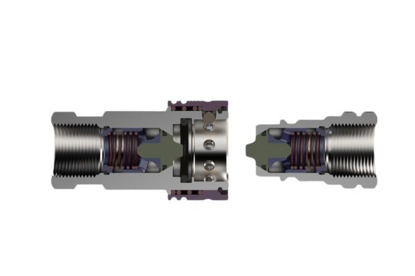
While a quick coupling may look simple from the outside, its interior is a complex landscape that the hydraulic fluid must navigate. Every turn, every change in diameter, and every obstruction contributes to pressure loss. The design of this internal path is what separates a high-performance coupling from a standard one.
Key Design Factors Influencing Cv:
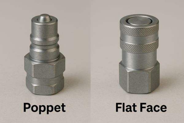
- Valve Type: This is the most significant factor.
- Poppet-Style (e.g., ISO 7241-A): This design uses a poppet valve that sits directly in the flow path. Even when fully open, the poppet and its retaining structure create a major obstruction, forcing the fluid to make sharp turns and squeeze through a reduced area. This creates high levels of turbulence and results in a lower Cv value.
- Flat-Face Style (e.g., ISO 16028): High-quality flat-face couplers are often designed with a more streamlined internal valve. The valve can be shaped to guide the fluid smoothly around it, creating a more laminar flow path with fewer sharp turns. This superior hydraulic design results in a significantly higher Cv value for the same body size.
- Spring Design: The spring that holds the valve closed must be compressed during operation. A heavier spring requires more energy (pressure) to keep the valve open, which contributes to the overall pressure drop. The design goal is a spring that is strong enough to create a reliable seal when disconnected but as light as possible to minimize restriction when connected.
- Machining and Finish: The smoothness of the internal surfaces also plays a role. A rough, poorly machined surface creates more skin friction than a smooth, finished one, contributing to a small but measurable increase in pressure drop.
When we work with our manufacturing partners, we place a heavy emphasis on these internal design characteristics. Optimizing the flow path is how we deliver couplings that provide superior performance to our customers, allowing their machines to run cooler and more efficiently.
How Do I Select the Right Coupler for My Flow Rate?
Choosing a new coupler based only on the thread size of the port seems logical. But this common mistake often results in an inefficient connection that compromises the entire system’s performance.
Selection should be based on the system’s flow rate and acceptable pressure drop, not just port size. Always consult the manufacturer’s pressure drop chart to ensure the coupler can handle the flow efficiently.

A Data-Driven Selection Process
Selecting the right quick coupling is a balancing act between size, cost, and performance. A data-driven approach ensures that the chosen component will enhance, not hinder, the hydraulic system.
Step 1: Define Your System Parameters
Before looking at any catalogs, you must know your system’s requirements:
- Maximum Flow Rate: What is the maximum GPM or LPM that will pass through this connection? Check the pump rating and system design specifications.
- System Pressure: What is the maximum operating pressure? The coupling must be rated to handle this pressure safely.
- Acceptable Pressure Drop: How much energy loss can you tolerate? For a return line, a higher drop (e.g., 30-50 PSI) might be acceptable. For a critical pressure line powering an attachment, you want the lowest possible drop (e.g., under 20 PSI) to maximize the power delivered to the tool.
Step 2: Consult Manufacturer Performance Charts
With your parameters defined, consult the pressure drop charts for potential coupling models. Do not just match the port size. For example, if you have a 1/2″ hose line, look at both 1/2″ and even 3/4″ body size couplers. Find your maximum flow rate on the chart’s horizontal axis. Move up to the curve for each model and read the corresponding pressure drop on the vertical axis.
Step 3: Make an Informed Decision
Consider this real-world scenario we often discuss with clients: A system requires 25 GPM through a 3/4″ line.
- Option A: A standard 3/4″ poppet-style coupler. The chart shows a pressure drop of 45 PSI at 25 GPM.
- Option B: A high-flow 3/4″ flat-face coupler. The chart shows a pressure drop of only 15 PSI at 25 GPM.
- Option C: A standard 1″ poppet-style coupler (adapted down). The chart shows a pressure drop of 10 PSI at 25 GPM.
Here, Option A meets the size requirement but creates significant heat. Option B is a far better choice for performance in the same size. Option C provides the best performance but may be physically larger and more expensive. The best choice depends on the application’s sensitivity to performance, heat, and space constraints. Option B often represents the ideal balance.
What Are the Consequences of Undersizing a Coupler?
A newly installed coupler fits perfectly, but now the machine runs hotter and seems less powerful. This performance degradation indicates the new component is mismatched to the system’s hydraulic demands.
An undersized coupler creates a severe bottleneck, causing three main problems: excessive heat generation, massive energy waste, and sluggish, unresponsive performance from hydraulic actuators like cylinders and motors.
The System-Wide Impact of a Single Bottleneck
The consequences of installing a coupler with a low Cv value or one that is too small for the system’s flow rate extend far beyond the connection point itself. This single mistake can degrade the health and performance of the entire hydraulic system. The impact manifests in three critical areas:
1. Excessive Heat Generation
This is the most direct and damaging consequence. Every PSI of pressure dropped across the coupling is instantly converted into heat. A constant flow through a high-restriction coupling acts like a small, dedicated heater installed directly into your hydraulic line. This added heat raises the overall temperature of the hydraulic fluid. Hot oil has a lower viscosity, reducing its ability to lubricate properly. It also accelerates the rate of fluid oxidation, forming sludge and varnish that can clog filters and stick valves. Most critically, sustained high temperatures will cook the elastomeric seals throughout the system, making them hard and brittle and leading to widespread leaks.
2. Wasted Energy
The hydraulic pump must work harder to push fluid through the restrictive coupling. The energy required to overcome this unnecessary pressure drop is completely wasted. For mobile equipment, this translates directly into increased fuel consumption as the diesel engine must produce more horsepower to drive the less-efficient hydraulic pump. For stationary industrial machinery, it means a higher electricity bill. This wasted energy offers zero productive output; its only product is damaging heat.
3. Sluggish Actuator Performance
The pressure available to do work at a hydraulic cylinder or motor is the system pressure minus all the pressure drops along the line. If a restrictive quick coupling introduces a 100 PSI drop, that is 100 PSI that is not available to push, pull, lift, or turn. This results in actuators that move more slowly and can generate less force than they were designed for. A powerful machine will feel weak and unresponsive, all because of an incorrect component choice at a single connection point.
| Consequence | Cause | System-Level Impact |
| Excessive Heat | Pressure drop converted to thermal energy. | Fluid degradation, seal hardening, component failure. |
| Wasted Energy | Pump works harder to overcome restriction. | Higher fuel/electricity consumption, reduced efficiency. |
| Poor Performance | Pressure is lost before reaching the actuator. | Slow cylinder/motor speeds, reduced lifting force. |
Conclusion
Efficient hydraulic performance depends on minimizing pressure loss. Selecting a quick coupling based on its Cv value for your system’s flow rate, not just its size, is crucial for success.