Excavator hydraulic hose failure triggers costly downtime, environmental liability, and critical safety hazards in heavy equipment. This guide details visual signs, performance metrics, and industry standards for inspection and replacement, empowering professionals to ensure site safety, compliance, and fleet efficiency.
Visual Indicators of Imminent Excavator Hose Failure
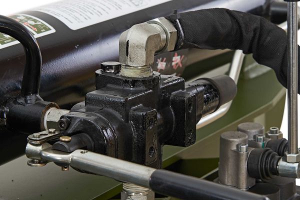
Visual inspection is the primary diagnostic tool in hydraulic maintenance, serving as the first line of defense against catastrophic failure. The external condition of a excavator hose assembly is rarely cosmetic; it is a direct reflection of the component’s structural integrity and its ability to withstand the extreme pressures of modern excavation equipment. Operators and fleet technicians must be trained not only to look but to interpret the physical degradation of hose materials.
Cracked or Abraded Outer Covers
The outer cover of a hydraulic hose is a sacrificial layer, typically made of synthetic rubber (neoprene or nitrile), designed to protect the critical reinforcement layers from environmental and mechanical hazards. However, it is susceptible to elastomeric degradation. This process is accelerated by exposure to UV radiation, ozone, and extreme temperature fluctuations, manifesting as a network of fine cracks known as “checking.”
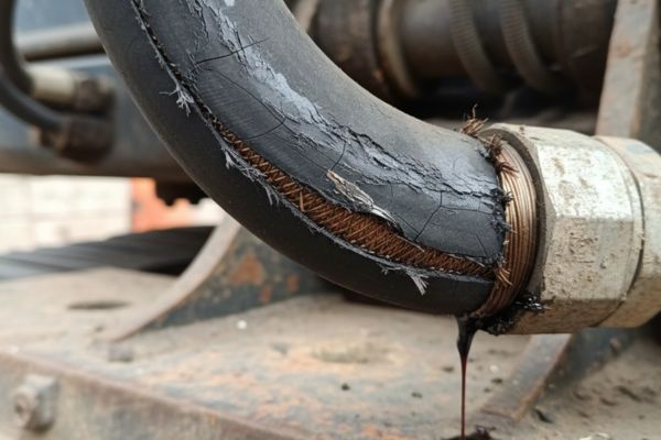
While minor surface checking is common, it signals that the rubber is losing its plasticity. The danger escalates when these cracks deepen or when mechanical abrasion wears the cover down. If the steel wire reinforcement becomes visible—whether through a deep cut, abrasion, or cracking—the hose has lost its primary defense against moisture. Once water ingresses to the steel braid, oxidation (rust) begins immediately. Corroded wires lose their tensile strength rapidly, significantly reducing the hose’s burst pressure threshold. Under SAE J517 standards, any hose with exposed wire reinforcement is non-compliant and must be removed from service immediately to prevent a burst.
Bulges, Blisters, and Swelling
A bulge or blister on the surface of a hydraulic hose is a critical alarm signal that indicates the pressure-retaining integrity of the inner tube has failed. This phenomenon occurs when the inner liner develops micropores or pinholes, allowing high-pressure fluid to migrate through the tube and become trapped between the liner and the outer cover.
Because the outer cover is not designed to contain system pressure (which can exceed 5,000 PSI / 345 Bar in modern excavators), the trapped fluid creates a pressurized pocket. This blister is essentially a “ticking time bomb.” It indicates that the hose’s structural capacity is compromised and that the only thing preventing a massive rupture is a thin layer of unreinforced rubber. Technicians must never touch a pressurized blister to test its firmness, as it could burst upon contact. The presence of a blister requires immediate machine shutdown and lockout/tagout procedures.
Fluid Weeping at Fittings
Moisture, oil residue, or “weeping” around the metal crimp fittings is often dismissed as residual grease or sweating, but it is frequently a sign of cold flow or fitting detachment. Cold flow occurs when the rubber hose material, under the constant compression of the crimp shell, loses its elasticity over time and “flows” away from the pressure point. This relaxation breaks the seal between the hose and the fitting.
Alternatively, weeping can signal that the hose is pulling out of the fitting due to improper assembly (incorrect insertion depth) or because the hose was cut too short to accommodate the natural length changes (up to +2% or -4%) that occur during pressurization. Even minor weeping reduces system pressure and creates significant liabilities: it introduces slip hazards on the machine deck, contaminates the soil leading to environmental fines, and poses a fire risk if the leaking fluid contacts hot engine components like turbochargers.
Performance-Based Warning Signs
Hydraulic systems are closed loops where pressure and flow are inextricably linked to machine performance. Often, a hose will fail internally before it shows external signs of damage. The machine communicates this distress through subtle changes in operation, auditory anomalies, or thermal spikes.
Sluggish or Jerky Operation
When an excavator’s boom, arm, or bucket moves slowly (sluggishness) or exhibits a stuttering motion (jerkiness), the operator may initially blame the hydraulic pump. However, the root cause is frequently a collapsed inner tube within a hose. This is known as internal delamination.
Over time, the inner tube can separate from the reinforcement layer, creating a loose flap of rubber inside the hose. This flap acts like a check valve or a throttle, intermittently restricting fluid flow. When the operator demands power, the pump forces fluid against this blockage, resulting in reduced volumetric flow to the cylinder. This manifests as extended cycle times and unresponsive controls. If the machine feels “spongy” or inconsistent, and no external leaks are visible, maintenance teams should inspect hoses for soft spots or kinks that indicate internal collapse.
Abnormal Noise and Vibration
A healthy hydraulic system operates with a consistent, rhythmic hum. Deviations from this acoustic baseline are critical diagnostic clues.
- High-Pitched Hissing: This usually indicates a high-pressure leak where fluid is escaping through a microscopic orifice at high velocity. This phenomenon, known as wire drawing, can cut through adjacent metal components like a laser.
- Chattering or Hammering: While often associated with aeration (air in the oil) or cavitation, these sounds can also result from a hose that is undersized for the flow rate. When fluid velocity becomes excessive, it creates turbulence rather than laminar flow. This turbulence generates vibration that travels through the assembly, fatiguing metal fittings and loosening clamps throughout the machine.
- Groaning: This can occur when a suction hose collapses, starving the pump of oil (cavitation). This is destructive to the pump and requires immediate investigation of the supply lines.
System Overheating
Heat is the enemy of hydraulic longevity. Every hydraulic system has an optimal operating temperature range, typically between 110°F and 150°F (43°C – 65°C). If the fluid temperature spikes above 180°F (82°C) without a corresponding heavy load or high ambient temperature, it indicates a system inefficiency.
A restricted hose creates a pressure drop (ΔP) across the blockage. According to the laws of thermodynamics, this wasted energy is converted directly into heat. If a hose has internally collapsed or if an undersized replacement was installed, the pump has to work harder to push fluid through the narrow opening, generating excess heat. Chronic overheating accelerates the chemical breakdown of all rubber seals and hoses in the system (heat aging), causing them to become brittle and fail prematurely. Therefore, unexplained thermal spikes should trigger a comprehensive audit of the hose assemblies for restrictions.
Root Causes of Hydraulic Assembly Breakdown
Understanding why a hose failed is as important as replacing it. Simply installing a new hose without correcting the underlying environmental or mechanical issue guarantees a repeat failure. Root cause analysis distinguishes professional fleet management from reactive repair operations.
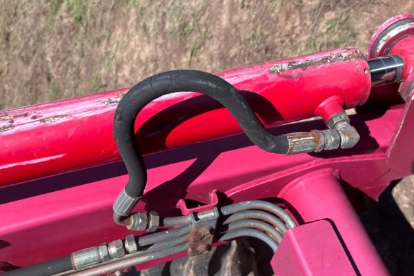
External Abrasion and Impact
Abrasion is the single leading cause of hydraulic hose failure in excavation environments. Excavators are dynamic machines; as the boom, stick, and bucket articulate, hoses flex and move. If a hose is routed improperly, it may rub against the sharp edges of the machine frame, rock guards, or even against other hoses.
This constant friction acts like sandpaper, wearing away the protective outer cover. Once the reinforcement is exposed, the hose is structurally compromised. Poor routing also leaves hoses vulnerable to impact damage. Falling rocks, rebar, or demolition debris can crush a hose, permanently deforming the wire reinforcement. This creates a stress concentration point where the hose will eventually burst under pressure. The use of spiral guard wraps, textile sleeves, and proper clamping techniques is essential to mitigate these risks.
Pressure Spikes and Fatigue
Hydraulic hoses are rated for a specific Maximum Working Pressure, usually with a 4:1 safety factor (burst pressure is four times the working pressure). However, excavators frequently endure shock loads. For example, when a bucket strikes an immovable rock or is dropped suddenly, the system experiences a transient pressure spike that occurs in milliseconds—far faster than the relief valve can open to dampen it.
These spikes can exceed the hose’s rated capacity significantly. This “water hammer” effect exerts massive tensile stress on the wire braiding. Over thousands of cycles, the steel wires suffer from metal fatigue and begin to snap internally. This damage is often invisible until the hose suddenly bursts during a standard lifting operation. Selecting hoses with high impulse cycle ratings (often exceeding SAE standards) is crucial for high-impact applications.
Table 1: Critical Hydraulic Hose Failure Indicators & Operational Impact
| Visual/Audible Sign | Probable Root Cause | Operational & Safety Impact |
| Cover Blisters / Bubbles | Pinhole leak in inner tube; fluid trapped under cover. | Critical Risk: Signals imminent explosive rupture. Requires immediate machine shutdown to prevent injury. |
| Exposed Wire Braid | Severe external abrasion (rubbing) or deep cuts. | High Risk: Structural integrity is lost. The hose cannot contain pressure spikes, leading to burst potential. |
| Weeping at Fittings | Cold flow of rubber, improper crimp, or vibration. | Medium Risk: Fluid loss, slip hazards, and expensive environmental contamination fines. |
| Fine Mist / Pinhole Spray | Micro-fractures in tube due to erosion/fatigue. | Severe Safety Hazard: High-pressure injection injuries (medical emergency) are likely if checked by hand. |
| Cracked/Brittle Cover | Heat aging (hardening) or UV/Ozone exposure. | Medium Risk: Loss of flexibility increases the likelihood of the hose snapping during articulation. |
| Kinked/Flattened Hose | Improper routing or exceeding minimum bend radius. | Performance Risk: Restricts flow, causes overheating and pump strain; eventually leads to fatigue failure. |
| Corroded Fittings | Moisture ingress or chemical incompatibility. | Structural Risk: Weakens the connection point; can lead to the fitting blowing off the hose entirely. |
Professional Inspection and Maintenance Strategy
Transitioning from “breakdown maintenance” (fixing it when it breaks) to “predictive maintenance” is the hallmark of a profitable heavy equipment operation. A structured inspection regimen allows site managers to schedule repairs during planned downtime, avoiding the massive costs of idle crews and emergency service calls.
The Daily Walk-Around Protocol
The daily walk-around should be a non-negotiable ritual for every operator. Before the engine starts, the operator must inspect the ground for fresh oil puddles and trace them to their source. Special attention must be paid to the “bight” or loop of the hoses on the boom and stick, as these areas experience the most severe flexing.
Industry leaders like Caterpillar and John Deere recommend periodic cleaning of the hydraulic compartment. Accumulated grease and dirt can hide weeping fittings, abrasion marks, or hairline cracks. If a hose is covered in mud, its condition cannot be assessed. The inspection should also verify that all safety clamps are intact; a missing clamp allows a hose to whip or rub, accelerating failure.
Monitoring Service Life Intervals
Hydraulic hoses are wear items with a finite lifespan, typically ranging from 5 to 10 years, or 8,000 to 12,000 operating hours, depending on severity of use. However, the rubber degrades purely due to time (shelf life), even if the machine is not used. This is due to the leaching of plasticizers and oxidation.
Proactive fleet managers implement “hard time” replacement schedules. For example, replacing all high-pressure boom lines every 4,000 hours creates a baseline of reliability. While this incurs an upfront cost, it virtually eliminates the risk of an on-site hose failure during a critical project phase. This approach also allows for bulk purchasing and planned technician time, which is far cheaper than emergency rates.
Checking Routing and Clamps
Correct routing is an art form that dictates the longevity of the assembly. Inspectors must verify:
- Twisting: A hose should never be twisted. A mere 7-degree twist during installation can reduce the hose’s service life by up to 90% because pressure pulses try to untwist the hose, tearing the reinforcement layers against the fitting.
- Bend Radius: Every hose has a minimum bend radius. Forcing a hose into a tighter curve causes the wire reinforcement to spread apart on the outside of the bend, creating a weak point.
- Clamping: Clamps should be tight enough to hold the hose but not so tight that they crush the wire reinforcement. The hose must be able to expand slightly under pressure.
Safe Replacement and Installation Procedures
When a hose is identified for replacement, the installation process must follow strict technical standards. Improper selection or installation is the primary cause of repeat failures. A replaced hose should last as long as, or longer than, the original if specified correctly.
The STAMP Selection Method
Never guess specifications based on visual appearance. Professionals use the STAMPED acronym to ensure the new assembly is safe and compatible:
- S – Size: Measure the Inside Diameter (ID). Using a smaller ID increases fluid velocity, causing heat and turbulence.
- T – Temperature: Ensure the hose material can withstand the system’s maximum oil temperature and the ambient environmental range.
- A – Application: Consider the routing, bend radius, and environmental exposure (rockfall, salt spray).
- M – Material: Verify chemical compatibility. Synthetic oils may require different tube compounds than mineral oils.
- P – Pressure: The hose’s Working Pressure must meet or exceed the system’s relief valve setting. Never use the burst pressure as a guide.
- E – Ends: Identify the correct thread type (JIC, ORFS, BSPP, SAE Flange) and seat angle. Mismatched threads are a leading leak cause.
Depressurization and Cleanliness
Safety begins with energy isolation. Hydraulic systems can store lethal energy even when the engine is off.
- Park Safely: Lower all implements (buckets, blades) to the ground.
- Depressurize: With the engine off and key in the “on” position, cycle the joysticks and pedals to bleed off residual pressure in the accumulators and lines.
- Venting: Carefully loosen the reservoir filler cap to vent tank pressure.
Cleanliness is critical. Modern hydraulic clearances are measured in microns (smaller than a red blood cell). Dirt is the enemy. Before removing a hose, clean the surrounding area thoroughly. Immediately cap the machine ports and the hose ends upon removal to prevent contamination. A single grain of sand introduced during a hose change can scour the swashplate of a piston pump or jam a spool valve, destroying the entire hydraulic system.
Table 2: Professional Hose Replacement Checklist
| Step | Action Detail | Required Tools/Materials |
| 1. Preparation | Lockout/Tagout machine. Depressurize system fully. | LOTO kit, PPE (Glasses/Gloves). |
| 2. Clean Area | Remove debris around fittings to prevent ingress. | Wire brush, solvent, rags. |
| 3. Identification | Use STAMPED method. Measure old hose length & fitting orientation. | Calipers, tape measure, thread gauge. |
| 4. Containment | Place absorbent pads/buckets under break points. | Spill kit, drain pans. |
| 5. Removal | Use backup wrench to prevent twisting the manifold/hardline. | Service wrenches (2x). |
| 6. Installation | Install new hose. Hand-tighten, then torque to spec. Do not twist. | Torque wrench, crowfoot adapters. |
| 7. Protection | Install abrasion sleeves or spiral wraps on high-wear areas. | Nylon sleeve, spiral guard. |
| 8. Testing | Top up fluid. Run machine at low idle, cycle controls, check for leaks. | Hyd fluid, cardboard (for leak check). |
Critical Safety Risks and Compliance
Hydraulic systems on modern excavators operate at extreme pressures, often exceeding 5,000 PSI (345 Bar). At these levels, hydraulic fluid behaves less like a liquid and more like a solid projectile. The safety risks associated with hose failure are life-threatening and require rigorous adherence to safety protocols.
High-Pressure Injection Injuries
The most insidious danger in hydraulics is the fluid injection injury. To the naked eye, a high-pressure pinhole leak may look like a harmless mist or be nearly invisible. However, the fluid velocity can exceed 600 feet per second. If an operator runs their hand over the hose to find the leak, the fluid can penetrate the skin as easily as a hypodermic needle.
This is not a simple cut or burn. The hydraulic fluid is toxic and is injected deep into the tissue, traveling along nerve pathways and fascia. It causes immediate chemical necrosis (tissue death) and Compartment Syndrome. The entry wound often looks like a minor bee sting, leading victims to ignore it. However, without immediate surgical debridement (cutting away affected tissue) within hours, amputation is frequently the only outcome.
Safety Rule #1: Never use bare hands to search for leaks. Always use a piece of cardboard or wood to pass over the suspected area.
Environmental and Fire Hazards
Hydraulic fluid is both a fire accelerant and an environmental pollutant.
- Fire: A burst line sprays atomized oil. If this mist contacts hot engine components like the turbocharger or exhaust manifold, it ignites instantly. The resulting fire can engulf an excavator in minutes. Keeping the engine bay clean of debris and shielding hoses from hot zones is critical.
- Environmental: Regulatory bodies (EPA in the US, EU directives) enforce strict penalties for soil contamination. A ruptured boom line can dump 20+ gallons of oil into the ground in seconds. This triggers expensive HazMat cleanup protocols and soil remediation requirements that can cost thousands of dollars, far exceeding the cost of the hose itself.
Industry Insights: OEM and Specialist Recommendations
Leading manufacturers and hydraulic specialists have moved away from reactive repairs toward a philosophy of total fluid power management. Understanding these industry trends helps operators maintain the resale value of their fleets and ensure compliance with modern safety standards.
Manufacturer Guidelines (Cat & Deere)
OEMs like Caterpillar, Komatsu, and John Deere integrate hydraulic health into their machine telematics. They advocate for Condition-Based Maintenance (CBM). Their maintenance manuals serve as the ultimate authority. For instance, Cat explicitly states that “if wire reinforcement is visible, the excavator hose assembly is failed.” There is no “watch and wait” period.
These manufacturers also stress Contamination Control. They recommend that whenever a hydraulic circuit is opened (like during a hose change), the system should be kidney-looped (filtered) if possible, or at minimum, extreme care taken to avoid ingress. They also standardize the use of abrasion sleeves on all hoses exposed to UV light or potential rubbing, viewing the sleeve as a cheap insurance policy for the expensive excavator hose assembly.
The “No-Patch” Standard
There is a prevalent but dangerous myth that hydraulic hoses can be repaired or spliced to save money. In the professional Western hydraulic industry, this is strictly prohibited for high-pressure applications.
A splice introduces two new potential leak points and a flow restriction. Furthermore, a used hose has already undergone fatigue; the rubber has hardened and taken a “compression set.” Attempting to crimp a new fitting onto an old, hardened hose will result in improper retention, leading to the fitting blowing off under pressure. The industry standard is binary: if a hose is damaged, the entire assembly must be replaced with a new, factory-spec unit.
FAQ
What visual signs indicate an excavator hose needs immediate replacement?
Immediate replacement is mandatory if you see exposed wire reinforcement (due to cuts or abrasion), blisters or bubbles on the cover, leaking crimped fittings, or deep cracks that penetrate the outer cover.
How frequently should I inspect hydraulic hoses on heavy equipment?
A visual walk-around looking for leaks and damage should be performed daily before every shift. A detailed inspection, involving opening panels and checking hidden routing and clamping, should be conducted every 500 operating hours or during scheduled services.
Why are hydraulic pinhole leaks dangerous to operators?
Pinhole leaks eject fluid at velocities capable of penetrating human skin (injection injury). This causes severe tissue death and requires immediate surgical intervention. Never use your hands to check for leaks; use cardboard to detect the spray.
Can I temporarily patch a damaged high-pressure hydraulic hose?
No. Patching or splicing high-pressure hydraulic hoses is unsafe and violates industry standards. Patches cannot withstand the system’s pressure spikes. The only safe repair is the replacement of the full assembly.
What is the STAMPED method for selecting replacement hoses?
STAMPED is the industry standard process to ensure the correct hose is selected: Size, Temperature, Application, Material, Pressure, Ends, and Delivery. Following this prevents installing a hose that is too weak or incompatible with the machine.
What is the leading cause of premature hose failure?
Abrasion (rubbing) is the #1 cause of failure. It occurs when hoses rub against machine frames, rocks, or other hoses. It can be prevented by using protective textile sleeves, spiral guards, and ensuring proper routing and clamping.