A leaking hydraulic fitting can bring your entire operation to a halt. Are you tired of dealing with frustrating oil leaks caused by a poor seal?
A qualified cone seal is judged by three core metrics: angle accuracy, surface finish, and its ability to withstand pressure. A proper cone must form a perfect metal-to-metal line of contact and pass a stringent air tightness test at 1.5 times its working pressure.
Checking seal quality requires a systematic method. This article will break down the inspection steps and tool selection, helping you prevent over 90% of failures that come from faulty seals.
Which Type of Hydraulic Cone Seal is Right for Your System?
Your system is leaking and you can’t figure out why. Mismatching cone seals is a common, costly mistake that leads to frustrating downtime and wasted resources.
Hydraulic cone seals are primarily classified by their angle. The most common types are the 24° cone (DIN standard, popular in Europe), the 37° flare (JIC standard, dominant in North America), and the 60° cone (BSPP standard, common in the UK and related markets).
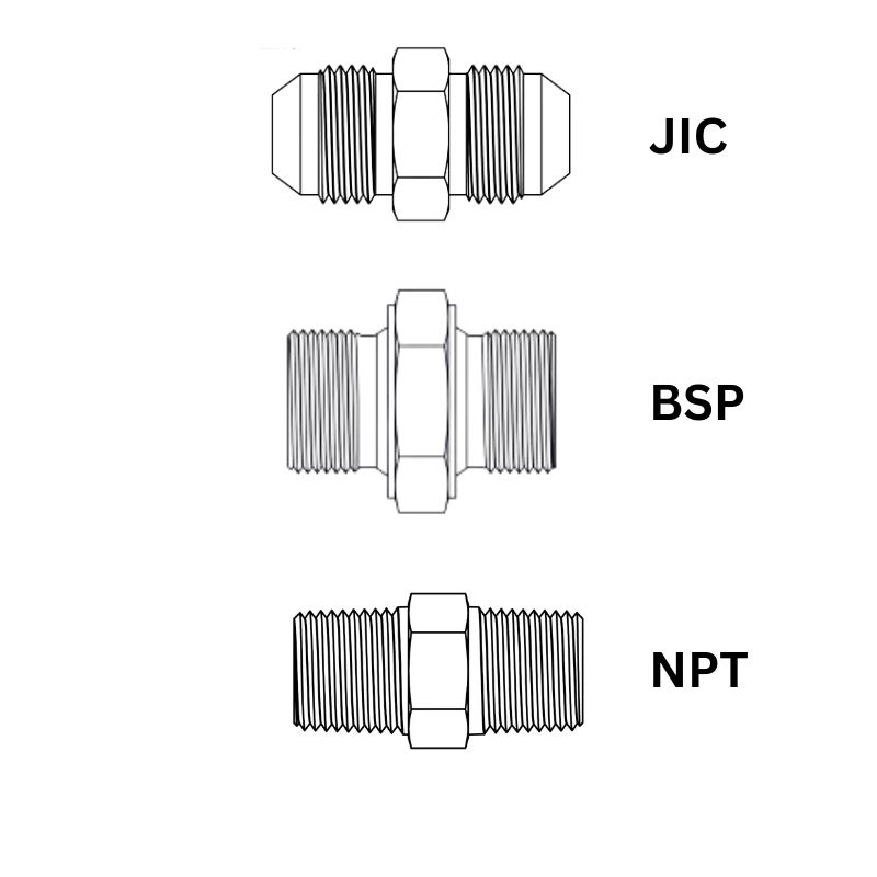
The sealing angle is the most critical feature defining a cone fitting, and it is crucial to understand that these angles are not interchangeable. A 37° fitting will never create a proper seal with a 24° port, no matter how much you tighten it. This is a fundamental concept for anyone working with hydraulic systems across different regions. I once had a client in the Philippines who couldn’t solve a persistent leak until we discovered they were using American JIC hoses (37° flare) with British adapters (60° cone). They look similar, but the mismatch creates a leak path.
The Main Contenders: 24°, 37°, and 60°
To help you identify them, here is a quick breakdown of the most prevalent types you will encounter in the global market:
| Seal Type | Common Standard(s) | Primary Region(s) | Key Feature |
| 24° Cone | DIN 2353, ISO 8434-1 | Europe, China, Global | Metric threads, often includes an O-ring (DKO type) for enhanced sealing. |
| 37° Flare | JIC, SAE J514 | North America, Global | Imperial (UNF) threads, purely metal-to-metal seal. |
| 60° Cone | BSPP, ISO 8434-6 | UK, Commonwealth, Japan | BSPP or NPT threads, seats on the 60° cone. |
We always advise our customers to use a thread and angle gauge to confirm both measurements before any installation. It’s a simple, five-second check that can save you hours of troubleshooting and prevent expensive oil spills.
Why Must the Cone Angle Tolerance Be Controlled Within ±0.5 Degrees?
Even a 1-degree angle deviation can reduce the contact area by 60%. This tiny error is more than enough to cause a seep or a full-blown leak under high pressure.
A precise cone angle ensures that contact stress is distributed evenly across the seal. When we use tools like a profile projector or a CMM machine for inspection, the acceptable tolerance for a standard 24° cone is typically very tight, often between -0.3° and +0.2°. For less critical applications, like some agricultural machinery fittings, this might be relaxed to ±0.8°.
In practice, inspecting the angle involves considering three key factors. You need to choose the right tool for the job. Not every workshop can afford a high-end coordinate measuring machine, but there are practical alternatives.
Choosing Your Inspection Tool
| Inspection Equipment | Best Use Case | Precision Level | Typical Cost |
| Angle Gauge | Quick on-site checks | ±0.5° | $$50 -$$200 |
| Profile Projector | Lab-grade measurement | ±0.1° | $8,000+ |
| CMM Machine | High-precision 3D analysis | ±0.02° | $30,000+ |
A common workshop method we often recommend for quick checks is the Prussian Blue test. It’s simple: you apply a thin layer of Prussian Blue paste to the cone surface. Then, you tighten the fitting to its specified torque and take it apart. A good seal will show a continuous, unbroken blue ring around the cone. This ring should cover at least 70% of the cone face’s height. For smaller fittings (under DN20), I always suggest using a 10x magnifying glass to get a clearer view of the contact pattern.
How Does Surface Roughness (Ra Value) Impact Sealing Performance?
Your seal looks perfect, but it still leaks. Could invisible surface flaws be the real culprit, silently undermining your system’s integrity?
When the surface roughness value, known as Ra, is greater than 0.8μm, the microscopic peaks and valleys on the metal surface become tiny channels for fluid to escape. This is a primary reason why many low-cost fittings fail prematurely. An ideal sealing face should have a roughness between Ra 0.2μm and 0.4μm. This range is the sweet spot—it’s smooth enough to form a tight seal through plastic deformation but retains just enough texture to hold a micro-layer of oil, which helps during assembly and prevents galling. At Topa, we use a profilometer for random sampling, measuring the Ra and Rz values at a minimum of 5 points on every batch.
The final surface finish is a direct result of the manufacturing process. Understanding these processes helps you know what you are paying for.
From Machining to Perfection
Standard Turning (Ra 1.6-3.2μm)
- This is the most economical method.
- It almost always requires a secondary grinding or polishing step to be suitable for sealing.
- It is generally only acceptable for very low-pressure applications.
Precision Grinding (Ra 0.4-0.8μm)
- This increases the manufacturing cost by about 40% compared to just turning.
- The finish is suitable for most medium and high-pressure hydraulic systems.
- This is the standard process we use for our fittings to guarantee reliable performance.
Superfinishing/Lapping (Ra 0.1-0.2μm)
- This can double the cost of the part.
- It’s reserved for ultra-high-pressure or critical applications, like in the aerospace industry.
- This process requires a temperature-controlled workshop environment to achieve.
From my experience, chasing an ultra-smooth finish of Ra < 0.1μm can sometimes be counterproductive. An overly smooth surface can trap moisture through adhesion, leading to corrosion. I always advise my customers to choose the appropriate grade based on their actual working pressure, not just aim for the smoothest possible finish.
How Can You Conduct a Pressure Test to Truly Reflect Seal Performance?
A visual inspection will miss over 80% of potential leak points. Are you relying on sight alone, potentially approving fittings that are destined to fail under real-world pressure?
The pneumatic pressure test is the final and most definitive proof of a seal’s integrity. To pass, a fitting must hold 1.5 times its maximum working pressure for a set duration with no detectable leaks or pressure drop. This method is superior because tiny gas molecules can escape through flaws that would trap larger liquid molecules.
Simply put, if a seal can hold high-pressure gas, it can absolutely hold hydraulic fluid. At our factory, we submerge the pressurized assembly in a water tank; any leak, no matter how small, becomes immediately visible as a stream of bubbles. It’s an undeniable truth test. But the key is in how you run the test. A one-size-fits-all approach is a recipe for either missing a critical flaw or over-stressing a part unnecessarily.
The Gold Standard: A Staged Pressurization Protocol
A cheap test just cranks up the pressure all at once. A professional test is a controlled, staged process. We always use nitrogen instead of compressed air due to safety—nitrogen is inert and won’t support combustion in the case of a catastrophic failure. Our protocol looks like this:
- Seal Confirmation (0.5 MPa): A quick, low-pressure check to ensure the test rig is sealed correctly.
- Ramp to 50% Working Pressure: A slow and steady increase.
- Ramp to 100% Working Pressure: We pause here to let the materials stabilize.
- Ramp to Test Pressure (1.5x Working Pressure): This is the peak stress phase.
- Hold and Monitor: We begin the clock for the hold time only after the pressure has stabilized at the test peak.
This gradual process allows the metal-to-metal seal to properly “seat” and prevents the shock of sudden pressurization from giving a false result.
Customizing the Test for Your Application
The test parameters must match the system’s demands. High-pressure systems require more stringent testing because the consequences of failure are so much greater.
| System Type | Low-Pressure System (<25MPa) | High-Pressure System (>25MPa) |
| Test Medium | Air or Nitrogen | Nitrogen ONLY (for safety) |
| Pressurization | Pressurize in 3 gradual steps | Pressurize in 4-5 steps to allow material stabilization |
| Hold Time | Minimum 3 minutes | Minimum 5 minutes (micro-leaks take longer to show) |
| Allowable Pressure Drop | ≤0.1 MPa/min | ≤0.05 MPa/min |
| Safety | Standard safety protocols | Must include a pressure relief valve and a blast shield |
How Can You Use Failure Analysis to Improve Your Seal Design?
Recurring failures are frustrating and expensive. Are you tired of replacing the same leaking fittings without ever understanding the root cause of the problem?
Understanding why a seal failed is the key to preventing it from happening again. From what I’ve seen over the years, about 80% of cone seal problems can be traced back to three typical failure modes. Learning to recognize these patterns helps you address the core issue, not just the symptom. The most common failure is eccentric wear on the cone, which shows up as a heavy contact mark on one side and no contact on the other. This is usually caused by poor concentricity between the threads and the cone, or by uneven torque during installation. This is why we always stress the importance of using a calibrated torque wrench and tightening the nut in three incremental steps.
When you encounter a failure, documenting it is crucial. We encourage our clients to build a simple failure analysis database.
Building Your Failure Analysis Matrix
| Dimension | What to Record |
| Failure Mode | Describe the visual evidence: Was it an annular wear pattern, pitting from corrosion, or axial stress cracks? |
| Root Cause | Investigate why: Was the material hardness too low (less than 350 HV)? Was the plating uneven (<8μm)? Did heat treatment cause distortion? |
| Solution | Define the fix: Should we add a pilot to improve alignment? Switch to a nitriding surface treatment? Or optimize the annealing curve post-forging? |
Last year, we helped an agricultural equipment manufacturer in Australia analyze a persistent field failure. Their fittings were failing after just six months. Our analysis showed the issue was a combination of high vibration and pressure spikes. We switched them to a modified 60° short cone design and added a special PTFE coating to the seal. This small change extended the service life to over three years. It was a perfect example of how a small, focused improvement can deliver a huge return.
Mastering checks for angle, roughness, pressure, and failure analysis are the four pillars of guaranteeing a qualified seal.