A hose can be cut to the number written on a shop traveler and still finish too long or too short after crimping. The usual problem is not the cut itself; it is an unclear relationship between the bare hose length and the reference points on both installed ends. A one-piece fitting cut-off factor describes the portion each fitting contributes between the hose cut end and the specified finished-length reference. Straight, 45-degree, and 90-degree ends may use different references, so the technician must confirm the drawing convention before cutting.
Why a Correctly Cut Hose Can Finish at the Wrong Length
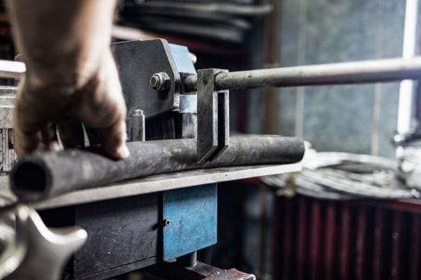
The cutting station controls one physical dimension: the length of bare hose between its two cut faces. The assembly drawing usually controls another: a finished dimension between seats, sealing faces, centerlines, or other defined end references. If the traveler gives a cut length derived from the wrong references, accurate cutting simply reproduces the calculation error.
Start with the finished reference, not the saw
Before calculating anything, trace the dimension arrows on the assembly drawing. Identify exactly where the finished length begins and ends, whether elbow orientation affects the reference, and whether protective caps or loose nuts are excluded. A note that says only “overall length” is not enough when a swivel nut can move or an elbow has more than one reasonable measuring point.
The same discipline applies when copying an old assembly. A tape measurement across the furthest visible points may include nut projection, elbow height, or deformation that the original drawing did not define. The old hose is evidence, not an automatic master. Record how it was measured and compare that method with the intended installation interfaces.
Keep cutting accuracy separate from calculation accuracy
Cut-face squareness, hose compression during measuring, and tape placement affect shop accuracy. They do not correct a mistaken take-up value. Treat the work as two controls: engineering defines the length relationship, and production reproduces the approved cut length. Mixing those responsibilities makes troubleshooting difficult because the final error cannot be traced to its source.
What the One-Piece Fitting Cut-Off Factor Represents
Cut-off factor is a length-build-up term, not a universal fitting property. It connects the bare hose cut end to the finished assembly reference for one exact fitting geometry, size, and drawing convention. It may also be described as fitting take-up, but the terminology must be defined in the document being used.
Distinguish three related lengths
The following terms should never be treated as synonyms:
- Cut length is the bare hose length before fittings are installed.
- Fitting take-up or cut-off factor is the contribution from a hose cut face to the specified external reference after correct insertion and crimping.
- Finished assembly length is the controlled distance between the two references named on the assembly drawing.
Insertion length is related but not identical. It describes how far the hose or fitting stem engages during assembly, according to the applicable fitting and hose instructions. The finished reference may be beyond the stem shoulder, at a sealing seat, or at an elbow centerline. Therefore, an insertion mark cannot be substituted for the cut-off factor unless the approved engineering data explicitly establishes that relationship.
Exact geometry and size control the value
A one-piece fitting has a stem or nipple and ferrule preassembled, attached, or retained together, but that structure alone does not determine take-up. End connection, straight or elbow form, port size, hose side, nut design, and dimensional revision can all change the reference distance. Use cut-off data only for the exact part number or controlled geometry shown in the approved source.
Reference Points Change with Fitting Geometry
Straight and elbow fittings must be measured by their defined functional references, not by whichever surfaces are easiest to reach. A compact reference table prevents different operators from making different assumptions.
| Fitting geometry | Possible controlled reference | Main ambiguity to resolve before cutting |
| Straight male end | End face, sealing cone, or another drawing datum | Whether length is taken to the tip or the functional seat |
| Straight female swivel | Seat, nut face, or defined gauge point | Nut movement and whether the nut projection is included |
| 45-degree elbow | Intersection of centerlines or a specified functional point | How the virtual centerline is established and which plane is used |
| 90-degree elbow | Elbow centerline, seat, or drawing datum | Whether the dimension follows the centerline or reaches an external surface |
Straight ends still require a named datum
A straight fitting appears simple, yet a male tip, flare seat, flat sealing face, swivel nut, and port shoulder are different locations. The drawing must name the datum or show unambiguous dimension arrows. If a shop measurement is taken to a convenient external face while engineering calculated to a sealing seat, the error becomes part of every finished assembly.
Loose components also need a stated position. A swivel nut should not be forced to one arbitrary extreme unless the specification defines that condition. Measuring fixtures or gauge blocks are useful only when their contact points reproduce the approved finished-length references.
Elbows introduce virtual references and planes
An elbow often uses the intersection of the hose centerline and the connection centerline as a dimensional reference. That point may exist only on the drawing, so the shop needs a fixture, height gauge, or documented projection method to reproduce it. Measuring to the outer curve of the elbow or the end of a nut produces a different length relationship.
Orientation also matters. A 45-degree or 90-degree fitting may be correctly positioned along the hose but clocked into the wrong plane. Length and clocking should be verified separately: one controls reference-to-reference distance, while the other controls the angular relationship needed for installation.
Build the Finished Hose Length from Both Ends
Every two-ended hose assembly is a combined geometry. The first fitting contribution, the bare hose cut length, and the second fitting contribution must all use compatible signs and references. A valid value for one end cannot repair a wrong value or wrong datum on the other.
Assign each end independently
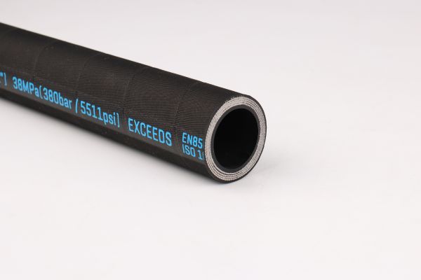
Label the ends before calculation, for example End A and End B. For each end, record the exact part number, geometry, hose side, finished-length datum, cut-off source, and revision. If one end is straight and the other is an elbow, do not assume the same type of reference or take-up convention applies.
For two elbows, add the required clocking information as a separate controlled characteristic. The cut length may remain a scalar dimension, but the finished assembly also needs an angular definition between the connection planes. A traveler that contains only length cannot fully define that assembly.
Watch the sign convention
Some documents express fitting contribution as a quantity subtracted from finished length to obtain hose cut length. Other documents may present a signed offset or a direct cutting factor. Do not combine values from different systems until their definitions are reconciled. The safest shop document states the equation, labels the references, and identifies the source revision beside each factor.
Use a Symbolic Hose Assembly Length Calculation First
A symbolic relationship exposes missing information before numbers hide it. Let L be the specified finished assembly length between the approved external references. Let C1 be the contribution from the End A hose cut face to its finished reference, and C2 the corresponding contribution at End B.
The compact relationship is:
Bare hose cut length = L − C1 − C2
This expression is valid only when C1 and C2 are defined as positive contributions extending from each cut face toward the corresponding finished reference. If the controlled source uses another sign convention, follow that source rather than forcing its values into this relationship.
Validate the labels before substituting data
Ask four questions before using any values: Does L start and end at the intended datums? Does C1 belong to the exact End A fitting? Does C2 belong to the exact End B fitting? Are all three dimensions based on the same drawing revision and measurement convention? A “yes” based only on a similar product image or common dash size is not sufficient.
After the symbolic setup is approved, engineering may populate the controlled values from current fitting drawings or validated assembly data. The technician should receive the resulting cut length and a small datum sketch, not an unexplained calculation copied from another job.
Do not derive production factors from one finished sample
Reverse-calculating a factor from one old or newly crimped assembly can support investigation, but it does not establish controlled production data. Hose stretch, prior service, measurement method, insertion condition, and part revision can affect the observed result. Any derived value must be reviewed against authoritative drawings and the applicable hose-and-fitting assembly instructions before release.
Verify Drawings, Markups, and the First Assembly
The most reliable workflow proves the measurement method before a full cutting batch begins. A clear markup connects the engineering calculation to the fixture or hand measurement used on the shop floor.
Mark the document, then the hose
Create a controlled shop markup that shows End A, End B, L, C1, C2, both reference points, and elbow centerlines where relevant. Add the fitting part numbers and drawing revisions. On the hose, use the permitted insertion and orientation marks required by the applicable assembly process; do not invent an insertion depth from the cut-off calculation.
Before cutting, verify:
- The hose manufacturer, series, construction, ID, and dash size match the approved assembly combination.
- End A and End B fittings match the traveler and their cut-off data sources.
- The length datums are visible on the markup and reproducible with available measuring equipment.
- The cut-length formula and sign convention are stated rather than implied.
- Elbow orientation is controlled independently from the length calculation.
Prove the method with the first completed assembly
Cut, assemble, and crimp according to current approved hose, fitting, and crimp-equipment data. Then measure the completed assembly with the same datum method shown on the drawing. Confirm insertion evidence, finished length, and elbow clocking as separate results. If any result fails, contain the part and investigate before cutting the remaining hoses.
The first-piece check should also expose practical measurement problems. If operators cannot locate a virtual elbow centerline consistently, engineering may need a fixture or clearer gauge instruction. Changing the datum to make measurement easier is an engineering revision, not an informal shop-floor fix.
Recognize Reference Errors Before They Become Routing Problems
Incorrect references produce recognizable patterns. A consistent error across several assemblies often points to a wrong factor, datum, or sign convention; scattered errors may indicate cutting, insertion, component, or measuring variation. Diagnosis should begin by comparing the intended and actual measurement methods.
Common patterns include:
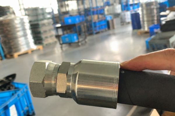
- Measuring a female swivel to the moving nut face when the drawing controls the seat.
- Using a straight fitting take-up for an elbow with the same hose dash.
- Measuring a 90-degree elbow to its outside envelope instead of the defined centerline.
- Subtracting one end contribution but accidentally adding the other.
- Copying cut length from an assembly with a different end style or revision.
- Treating an old, stretched, or deformed hose as an exact dimensional master.
A wrong finished length can place the installed hose under tension, remove necessary slack, violate the applicable minimum bend radius, force the hose to twist, or cause interference with nearby equipment. Do not pull an assembly into place to hide a length error. Stop the equipment, isolate the hydraulic system, release pressure and stored energy, secure raised loads, and follow the equipment and component manufacturers’ procedures before inspection or replacement.
The final pre-cut release should confirm the drawing revision, End A and End B identities, reference datums, C1 and C2 sources, symbolic relationship, calculated cut length, hose specification, measuring method, and required clocking. That short record makes the next repeat order traceable and prevents an unexplained shop correction from becoming permanent data.
Conclusion
Finished hose length is built from the bare hose and both fitting ends, so cutting control begins with defined datums rather than the saw. Identify End A and End B, confirm each exact fitting geometry and revision, and keep insertion and clocking requirements separate from length take-up. Use a labeled relationship such as L, C1, and C2 to expose missing or incompatible references before applying controlled values. Then prove the method on the first completed assembly using the same measurement convention shown on the drawing. A reliable one-piece fitting cut-off factor must belong to the exact part and reference system; it should never be copied from visual similarity, nominal hose size, or an unexplained old assembly. Prepare the drawings, factor sources, hose data, and measuring method before cutting.
FAQ
How should cut length be handled when both ends are elbows?
Calculate each elbow contribution independently and control their clocking as a separate characteristic. The finished drawing must define both length datums and the angular relationship between the elbow planes.
Can straight and elbow end styles use the same cut-off factor?
Not unless controlled data explicitly shows the same defined contribution for those exact parts. Different geometry and reference points usually require separate confirmation even when the hose dash is identical.
What should the shop do when “overall length” is ambiguous?
Stop the calculation and obtain a clarified datum sketch or revised drawing. Choosing a convenient tip, nut face, seat, or centerline without approval can create a repeatable but incorrect assembly.
Can a hose be re-crimped to correct a finished-length error?
Do not re-crimp unless a verified procedure specifically permits it for the exact hose and fitting system. Length errors normally require technical disposition because additional compression or repositioning can damage the assembly.
Is an old hose assembly a reliable source for finished length?
It is supporting evidence, not definitive production data. Record its installation references, condition, deformation, end geometry, and measurement method, then reconcile those observations with current drawings and approved assembly information.