A finished hose can contain the correct hose, fitting series, and end connections yet still be impossible to install without twisting. The failure is usually geometric: an elbow was clocked from an unstable reference, moved before crimping, or was never checked after the dies opened. Controlling 45 and 90 degree one-piece fitting orientation requires one fixed end, a defined reference plane, visible process marks, and separate before-and-after inspections. The method should reproduce the assembly drawing without forcing the hose into position. This process note explains how to align, mark, hold, crimp, and recheck angled ends while avoiding unsupported universal angular tolerances.
A Correct Hose Can Still Fail at Installation
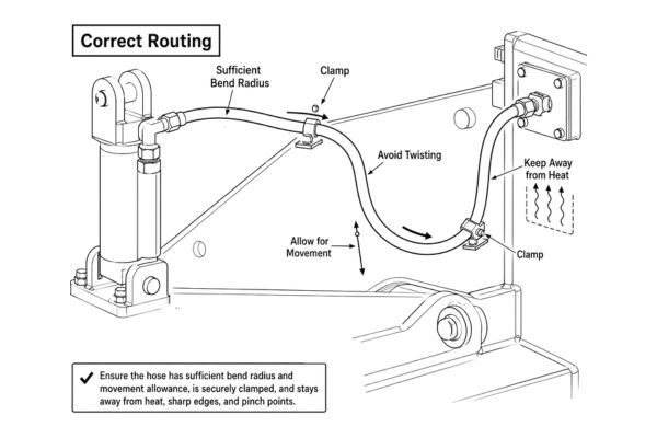
Wrong clocking becomes obvious when the assembly reaches the machine: one connection aligns, but the other points away from its port. Rotating the second end may appear to solve the problem, yet the hose body then carries torsional stress. A hose is intended to flex through its designed bend, not act as a torsion spring between fixed ports.
The immediate response should be containment, not forced installation. Identify the assembly, drawing revision, end designations, measured orientation, and stage at which the error was discovered. If the line has already been installed, stop and isolate the hydraulic system, release pressure and stored energy, secure raised loads, and follow applicable lockout and equipment procedures before disturbing it.
Separate component correctness from geometric correctness
Part verification answers whether the hose and fittings belong together under current approved assembly data. Orientation verification answers whether the angled connections occupy the required planes. Passing one check does not imply passing the other. A shop traveler should therefore record fitting identity, insertion evidence, crimp result, finished length, and elbow clocking as separate characteristics.
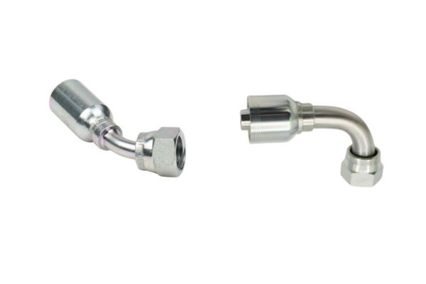
An angled fitting also has two geometric features that must not be confused. Its bend shape establishes the connection direction relative to the hose centerline, while clocking establishes rotation around that hose centerline. A 90-degree elbow can have the correct bend geometry and still point to the wrong clock position.
Define Clocking with One Fixed Reference
Clocking is the angular relationship between an angled end and a repeatable reference plane. The reference may come from the other elbow, a straight-end feature, a controlled fixture, or a drawing datum. It must be stated clearly enough that two operators set the same assembly without relying on how the hose happens to rest on a bench.
A clock-face description is useful when it is tied to a viewing direction. For example, the drawing may instruct the operator to look from End A toward End B, hold End A in its defined plane, and position End B at a specified clock location. Saying only “End B at three o’clock” is incomplete because reversing the viewing direction reverses the apparent relationship.
Choose and lock End A
Designate one fitting as End A before positioning the other. Place End A in a fixture or against a flat reference that contacts an approved feature without damaging the sealing face, threads, O-ring, or swivel mechanism. The fixture should stop rotation and establish the drawing plane; it should not depend on an operator pressing the part by hand at an approximate angle.
If End A is straight, use a feature that actually defines a plane, such as an approved wrench-flat orientation or another drawing datum. A cylindrical straight fitting with no rotationally meaningful feature cannot establish clocking by itself. In that case, the hose layline, an added process mark, or an external fixture datum may define the temporary assembly reference.
State the viewing direction and reference feature
The traveler or markup should contain four items together: End A identity, the feature held as zero, the direction of view, and End B target orientation. A small end-view sketch is often clearer than prose. It should also distinguish clocking from the finished length datum so that operators do not use a movable nut or convenient outer elbow surface as both references.
Mark the Hose and Fittings for Repeatability
Marks turn an invisible rotational relationship into a visible process control. They support positioning and reveal movement, but only when their purpose and reference are defined. A random paint line or hose layline is not automatically a dimensional datum.
The hose layline can provide a longitudinal reference because it runs along the hose body. Its printed position may vary relative to the internal reinforcement or natural hose curvature, so it should be treated as a repeatable visual aid rather than proof of structural orientation. If the procedure uses it, state exactly which edge or center of the layline is referenced and how the hose is supported.
Align and mark before crimping
After confirming insertion according to current hose, fitting, and crimp-equipment instructions, place a temporary witness mark across the hose and ferrule where permitted. Add a separate longitudinal mark that shows the intended orientation plane. The marks should remain visible after handling and should not contaminate sealing surfaces or interfere with inspection.
A practical pre-crimp record may include:
- End A and End B part numbers and geometries.
- Viewing direction and zero-reference feature.
- Required clocking from the controlled drawing.
- Hose layline or temporary datum used during setup.
- Insertion mark status and applicable assembly-data revision.
- Operator or station confirmation before the assembly enters the crimper.
Use marks as evidence, not as a substitute for a fixture
A witness mark can show that a ferrule moved relative to the hose or that an elbow rotated from its setup position. It cannot prove the final angle by itself. Flexible hose may roll on the bench, and wide marks can hide small shifts. Final acceptance should use the approved fixture, gauge, template, or measurement method defined for the assembly.
For repeat work, preserve the datum sketch and fixture identity with the part record. Informal marks copied from a previous hose can transfer an old error, particularly when end styles or fitting revisions have changed.
Control One-Elbow and Two-Elbow Assemblies Differently
One-elbow assemblies need an external orientation reference; two-elbow assemblies usually need a controlled end-to-end angular relationship. Treating them as the same setup creates ambiguity about which feature defines zero.
One elbow with a straight end
When only one end is angled, establish how that elbow must relate to the machine installation plane, mounting feature, hose layline, or assembly drawing. A straight swivel end may rotate during installation and therefore may not provide a reliable plane. The drawing should define the elbow orientation independently or identify a controlled reference on the straight end.
Support the hose in a neutral, untwisted condition. Natural curvature should not be forced flat merely to align a paint line. If the hose is allowed to relax differently between setup and inspection, the elbow may appear to change orientation even though the fitting has not moved relative to the hose.
Two elbows on the same hose
For two elbows, lock End A at zero and rotate End B to the defined clock position while viewing in the stated direction. The relevant output is the angle between the two connection planes, not their appearance relative to the workbench. Both ends must also retain their specified insertion and finished-length conditions.
Opposite-plane routing deserves explicit drawing treatment. Terms such as “opposed,” “back-to-back,” or “same plane” may be interpreted differently unless paired with a view or datum. Use a controlled end-view sketch and label the connection centerlines. Never infer the angle from a product photo whose perspective can distort the apparent relationship.
Align, Hold, Crimp, and Recheck
Orientation control must survive the crimping operation. Handling, die closure, hose relaxation, and fixture clearance may allow an elbow to rotate or the hose to roll. The process should therefore include checks on both sides of the crimper.
| Process stage | What to verify | Why it matters |
| Before crimp | Correct ends, insertion evidence, reference plane, viewing direction, target clocking | Prevents a wrong setup from becoming permanent |
| During loading | Marks remain aligned and the hose is not twisted or pulled | Detects movement caused by handling or crimper positioning |
| After crimp | Finished clocking, crimp result, insertion evidence, and finished length | Confirms the completed geometry rather than the intention |
Hold without loading the hose
Use a support or fixture that maintains orientation without bending the hose sharply near the fitting. Clamping the hose body aggressively can flatten the cover, disturb the setup, or store torsion that releases when the clamp opens. The fitting should be stable, but the hose should remain in its intended neutral condition.
Before starting the crimp cycle, confirm that the elbow clears the machine and tooling throughout closure. Do not rotate the fitting away from its mark simply to gain clearance unless engineering has approved a different loading method. A clearance problem is a process-design issue, not permission to change final clocking.
Recheck after the dies open
After crimping, let the assembly rest in the defined inspection condition, then place End A back in the same reference. Inspect End B with the approved method. Compare the witness marks and record the measured result separately from the pre-crimp setting.
Also verify the characteristics that orientation work can disturb:
- The hose was not twisted between the fittings.
- Insertion evidence remains consistent with the approved process.
- The finished assembly length uses the correct end references.
- The ferrule and hose show no damage from fixturing or handling.
- Crimp dimensions and inspection results meet current approved data for the exact hose and fitting series.
Do not create a universal allowance for expected crimp rotation. If a stable, repeatable shift exists, engineering should study the process and control the setup or fixture under documented approval rather than relying on operator compensation by feel.
Troubleshoot Wrong Orientation at the Process Step
When a finished angle is wrong, compare the actual assembly with the setup record before assigning a cause. A wrong pre-crimp mark suggests drawing interpretation or setup error. A correct pre-crimp mark with a shifted post-crimp position points toward holding, loading, fixture, or crimp-movement control.
Use the following sequence:
- Contain the assembly and any other parts made with the same setup.
- Confirm the drawing revision, viewing direction, End A datum, and required orientation.
- Verify the fitting identities and check whether one or both ends moved relative to their witness marks.
- Reproduce the setup in the fixture without forcing the hose.
- Inspect the crimper loading path, clearance, supports, and holding method.
- Correct the documented process and prove it on a controlled first assembly before releasing more work.
A completed hose should not be corrected by twisting the hose body, heating it, loosening a connection to an unsafe position, or attempting an unapproved re-crimp. Whether any rework is permissible depends on current manufacturer and approved assembly procedures for the exact combination. If no verified disposition exists, reject or hold the assembly rather than improvise.
Conclusion
Reliable elbow clocking comes from a defined geometry and a controlled process, not from visual alignment on a bench. Designate End A, state the zero feature and viewing direction, keep the hose neutral, and position End B from a drawing or fixture that operators can reproduce. Use laylines and witness marks to reveal movement, but verify the finished angle independently after crimping. One-elbow assemblies need an external plane; two-elbow assemblies need a clear end-to-end angular relationship. Never hide an orientation error by twisting the installed hose, because that can add torsional stress and routing problems. For repeatable 45 and 90 degree one-piece fitting orientation, prepare the end-view sketch, fixture method, assembly data revision, and before-and-after inspection record before production begins.
FAQ
How should two angled fittings be clocked on one hose?
Lock one fitting as End A and define the second fitting relative to that fixed plane and a stated viewing direction. The drawing should show the end-to-end angular relationship rather than relying on how the hose lies on a table.
What does opposite-plane routing mean for elbow orientation?
It must be defined by a controlled end-view or reference-plane drawing. Words such as opposite or back-to-back can be ambiguous when the operator views the assembly from the other end.
Can the hose layline be used as the only clocking reference?
Usually it should be treated as a visual process aid, not the sole acceptance datum. Its position and the hose’s natural curvature may vary, so the approved drawing or fixture must control the finished angle.
What if an elbow rotates slightly during crimping?
Measure the final orientation with the approved method and investigate any difference from the pre-crimp position. Do not assume a universal shift or compensate by feel; improve the holding and loading process under documented control.
Can a finished hose with wrong clocking be corrected?
Only an approved procedure for the exact hose-and-fitting system can authorize rework. Twisting the hose or attempting an unverified re-crimp may damage the assembly, so hold or reject it when no valid disposition exists.