The same nominal hose dash size does not justify the same crimp setting. Dash size usually identifies a nominal hose ID relationship, while one-piece fitting crimp specs between hose series respond to the complete assembly: hose outside diameter, cover, reinforcement, tube, fitting stem, ferrule, preparation, insertion, tooling, and validated final dimensions. Moving a setting from one series to another can therefore create too little or too much compression even when both hoses carry the same dash designation.
Same Dash Size Does Not Mean Same Crimp
Dash size is an identification field, not a complete assembly specification. It helps match nominal flow passage and connection sizing, but it does not define hose OD, reinforcement package, cover thickness, or how the hose responds when a ferrule is compressed around it.
The myth is simple: same dash size equals same crimp. The reality is that two hoses can share a dash designation while differing at every layer that the ferrule and stem engage. A crimp diameter copied from the first hose may leave the second combination undercompressed, overcompressed, or otherwise outside its approved assembly condition.
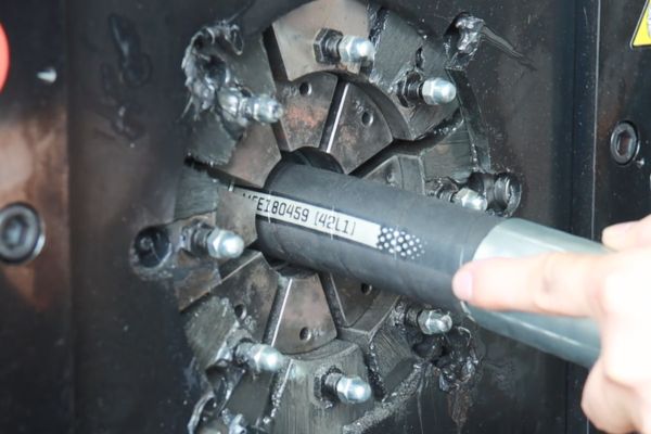
What dash size can and cannot tell you
Dash size can support initial product identification and help locate applicable data. It cannot independently confirm hose series fitting compatibility, die selection, skive requirement, insertion depth, crimp length, or final crimp target. Those controls must come from current approved data for the exact hose and fitting combination.
Treat a brand or series change as a technical change even when the order line still says the same dash size. The shop record should show the full hose manufacturer and series, not just a generic size description, because that identity determines which assembly table applies.
Hose Construction Changes the Starting Geometry
Crimping begins with the actual hose that enters the ferrule. Series-specific differences in tube, reinforcement, intermediate layers, and cover create different starting diameters and different resistance to compression. A visually similar hose is not evidence of identical construction.
Outside diameter and cover are only the visible differences
Hose OD determines the initial fit inside a ferrule, but OD alone does not describe what lies beneath the cover. A thicker or harder cover may resist initial closure differently from a thinner cover. A skived preparation removes selected material under a controlled procedure, while a no-skive preparation leaves the specified outer structure in place. Neither method should be assumed from appearance or transferred from another series.
OD variation also affects how the hose is loaded into tooling and how much radial movement is needed to reach the validated condition. This does not mean a technician should calculate a new target from the OD difference. It means the changed hose identity requires the approved target and preparation instructions associated with that series.
Reinforcement controls deeper compression behavior
Textile braid, wire braid, multiple braid layers, and spiral reinforcement do not react identically under radial compression. Wire size, layer arrangement, braid angle, interlayer material, and adhesion affect how force passes from ferrule to hose and stem. The reinforcement must be captured and supported as the fitting system was designed to engage it.
The inner tube matters as well. Stem serrations or engagement features interact through the tube and reinforcement structure, and excessive compression can damage the tube or disturb its intended bore. Insufficient compression may fail to establish the required retention or sealing condition. Only validated assembly data defines the acceptable result.
| What changed in the hose | Why it matters during crimping | What must be reverified |
| Outside diameter or cover construction | Changes initial ferrule fit and closure behavior | Approved fitting series, preparation, and final crimp target |
| Reinforcement type or layer arrangement | Changes stiffness, load transfer, and engagement | Stem/ferrule compatibility and validated assembly data |
| Tube or intermediate layers | Changes support around the stem and response to compression | Complete hose-and-fitting approval, not OD alone |
| Skive or no-skive instruction | Changes material remaining under the ferrule | Preparation method, tools, insertion, and inspection |
| Series revision | May change dimensions or construction without changing dash size | Current documents, effective revision, and traceability |
Compression Behavior Depends on the Complete Wall
Ferrule closure does not simply reduce an outside diameter to a smaller number. It creates a controlled mechanical relationship among ferrule, cover or prepared surface, reinforcement, tube, and fitting stem. Each layer changes how load is distributed and how the assembly reaches its intended retained condition.
An apparent final diameter also cannot prove that internal engagement is correct. Two assemblies may measure similarly outside while containing different hose-wall compression or stem interaction. Inspection must therefore use all required process controls, which may include correct components, preparation, insertion evidence, tooling, final dimensions, and any additional checks required by the approved procedure.
Undercompression and overcompression are different risks
Undercompression may leave inadequate engagement between the ferrule, reinforcement, and stem. Overcompression may damage the tube, reinforcement, fitting, or intended flow path. Neither condition should be diagnosed from a generic visual impression alone; the measured result must be compared with the current specification for that exact combination.
Trial-and-error adjustments are not a valid way to find the target. A hose shop should never close the dies progressively until the assembly “looks right,” because appearance does not establish retention, sealing, fatigue behavior, or application suitability.
Stem and Ferrule Geometry Form One System
A one-piece fitting normally has its stem and ferrule preassembled, attached, or retained together, with exact construction varying by series. This arrangement can reduce separate ferrule picking, but it does not make the fitting universal across hoses. Stem profile, ferrule length and wall, engagement features, and hose-tail geometry are selected as a system.
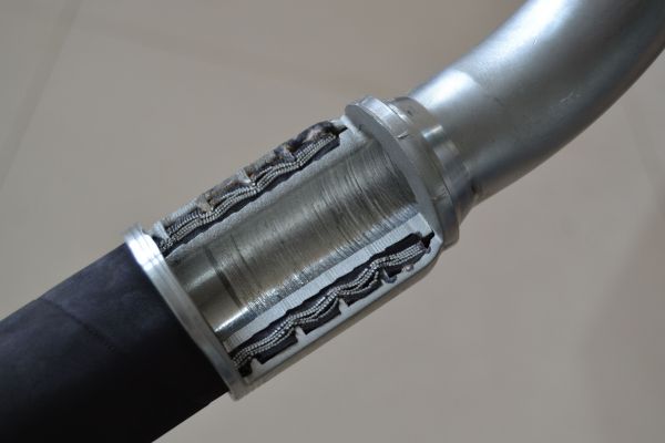
Changing only the hose can disrupt that system. A ferrule intended to engage one construction may contact another hose at a different location or compress a different reinforcement package. A stem that fits the nominal ID does not prove the assembly has the correct support, retention, sealing, or flow condition.
The ferrule cannot be evaluated separately
Ferrule identity must stay linked to the fitting stem and the approved hose series. Reusing a ferrule assumption from another fitting family because its outer shape appears similar is unsafe. Even where parts physically assemble, their controlled geometry and validated data may differ.
Likewise, matching a fitting by port end does not establish hose-side compatibility. Thread standard, seat, sealing face, and connection size control the machine-side interface; the stem, ferrule, hose series, and crimp specification control the hose-side assembly. Both sides must be correct.
Die Selection and Final Targets Are Series-Specific
The die set is part of the controlled process, not merely a tool that produces any requested diameter. Its profile, closure range, segment behavior, and relationship to the ferrule determine how compression is applied. A die used successfully for one series may not be approved for another, even when the nominal hose size matches.
Crimp length and the location of compression also matter. A final diameter measured at the wrong axial position may not represent the controlled result. Current instructions should define the equipment, die set, crimp position, measurement location, and acceptance method applicable to the exact assembly.
A reusable die is not a reusable setting
Sometimes approved data may specify the same tooling for more than one combination. That does not authorize carrying over the same machine setting or final target. Confirm each field independently from the current table rather than treating a familiar die number as proof that nothing else changed.
Machine condition, calibration, die wear, and setup can influence whether the equipment reproduces the specified result. Those controls support the approved crimp target; they do not create a replacement target when technical data is missing.
Verify Every Change from One Hose Series to Another
A series change should trigger a deliberate reset of the assembly record. Begin by identifying the outgoing and incoming hose completely, then retrieve the current approved data for the proposed combination. Do not rely on an old shop traveler that lists only dash size.
Use this verification path:
- Record hose manufacturer, full series, construction, nominal size, and relevant revision or traceability information.
- Confirm the exact one-piece fitting part number, stem/ferrule series, and hose-side size.
- Obtain current approved preparation, insertion, crimp-equipment, die, crimp location, and final inspection data.
- Compare the old and new records field by field; highlight every missing or changed instruction.
- Qualify the setup and first assembly under the organization’s approved procedure before releasing routine work.
- Preserve the data source and revision with the assembly record so repeat production uses the same controlled basis.
If current data does not list the combination, place it on hold. Similar OD, common brand ownership, a matching dash size, or physical fit does not authorize production. Engineering or the responsible manufacturer must provide an approved basis before assembly.
One Successful Sample Is Not Cross-Series Validation
A single sample that crimps without visible damage shows only that one assembly could be produced. It does not establish retention over service, sealing under operating conditions, pressure impulse performance, compatibility with fluid and temperature, or consistency across normal hose and component variation.
Validation scope should reflect the application and the organization’s approval requirements. It may require document review, dimensional inspection, controlled assembly evaluation, or additional testing defined by responsible engineering. This article cannot prescribe a universal test program, and a shop should not invent one in place of approved requirements.
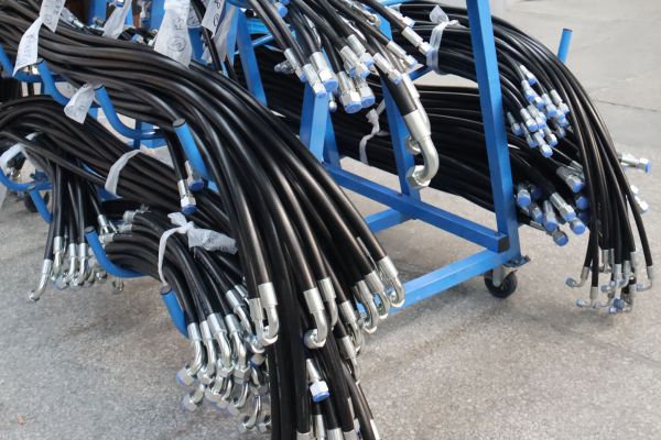
Compare the complete data package
Before releasing a cross-series change, confirm that the comparison record includes:
- Exact old and new hose identities, construction descriptions, and available OD controls.
- Approved fitting stem and ferrule identities for the new series.
- Preparation method, insertion control, die set, crimp location, and final target.
- Inspection method, equipment status, document revision, and effective date.
- Application inputs that remain relevant, including pressure, impulse, fluid, temperature, routing, and bend requirements.
The pressure suitability of the finished hose assembly is limited by the lowest-rated component and by the approved combination. A correct crimp record alone does not establish application suitability. Confirm the hose, fitting, adapter, port, and other components against the current system requirements.
Conclusion
Crimp data changes between hose series because dash size describes only part of the assembly. Hose OD, cover, reinforcement, tube, preparation, stem geometry, ferrule design, tooling, and inspection method work together to create the validated condition. When any hose series changes, reset the record: identify the new construction, confirm the exact fitting system, retrieve current preparation and crimp instructions, and prove the controlled setup before routine work. Never transfer a diameter, die assumption, insertion rule, or skive practice merely because the nominal size matches or one sample looks acceptable. Reliable one-piece fitting crimp specifications between hose series come from approved combination data and traceable revisions. Prepare the full hose and fitting identities, equipment details, and application requirements before authorizing the change.
FAQ
Can two hose series from the same brand use the same crimp data?
Only when current approved data explicitly lists the exact combinations and instructions. Common branding does not prove the series share construction, fitting compatibility, preparation, or final targets.
What if two hoses have the same dash size but different outside diameters?
Treat them as different assembly conditions and retrieve series-specific data. The OD difference signals changed starting geometry, but it is not enough to calculate a safe replacement target.
Can the same ferrule assumption be reused across hose series?
No assumption should be reused without approved system data. Ferrule engagement depends on the exact stem, hose construction, preparation, and validated crimp process.
Does using the same die mean the machine setting can stay unchanged?
No, because die identity and final crimp target are separate controls. Even when approved tables specify the same die, each combination may have different setup and inspection requirements.
What data should be requested before changing hose series?
Request the approved hose-and-fitting combination, preparation method, insertion control, crimp equipment, die set, crimp location, final target, inspection method, and current document revision. Also confirm pressure, fluid, temperature, and application requirements separately.