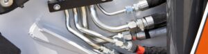
Hydraulic tube ovality can prevent proper assembly because the tube’s maximum outside dimension may interfere with a nut, ring, sleeve, or fitting body while its minimum dimension provides insufficient or uneven contact. The result can look like a wrong nominal size, a burr, coating buildup, or local damage, so a photograph or one caliper reading cannot establish the cause. Forcing the tube may scrape the outside surface, damage fitting components, or hide an unacceptable condition that later affects sealing.
Ovality Is a Shape Condition, Not a Nominal Size
Ovality means the tube cross-section is not acceptably round at the location being evaluated. A tube can have the correct nominal OD and still present different diameters when measured across different directions. Whether that variation is acceptable depends on the controlled tube specification and the exact fitting system.
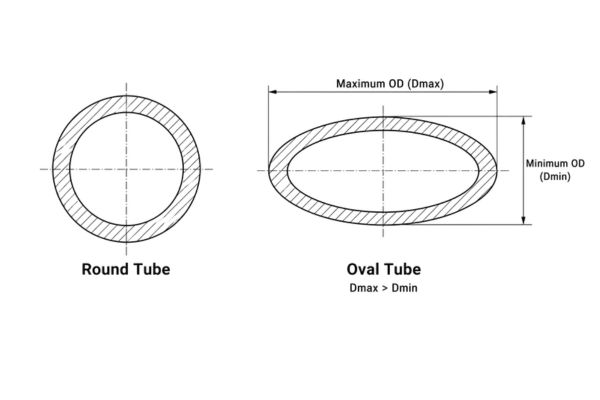
Maximum and minimum diameters matter
The practical problem is the difference between the largest and smallest measured outside diameters at one cross-section. The largest direction can block insertion or overload a local fitting feature, while the smallest direction can reduce intended circumferential contact. An average of the two may look close to nominal and conceal both problems.
Do not calculate or apply a universal ovality limit. Some tube specifications, fitting manufacturers, and equipment drawings define their own limits, measurement methods, or restrictions. The reviewer must use the current acceptance source that governs the delivered tube and connection.
The fitting interaction determines the consequence
Many tube fitting systems rely on consistent tube OD for entry, ring engagement, sealing contact, or controlled forming. Ovality can change how a cutting ring bites, how ferrules contact, or how a tube seats before flaring or assembly. The exact failure mechanism varies by system, so the diagnosis should describe observed interference or contact rather than claim a universal outcome.
Separate Ovality From Other Causes
An assembly problem should not be labeled ovality until competing explanations have been checked. Wrong nominal OD, a burr, coating, dirt, a raised weld area, and local deformation can all produce a tight fit or uneven reading. Each condition requires different evidence and disposition.
Symptom comparison
| Suspected condition | Evidence to collect | Important distinction |
| Tube ovality | Multiple OD readings around the same cross-section | Variation follows direction across a cross-section |
| Wrong tube OD | Multi-direction readings remain consistently outside the specified size | The whole section may be too large or small rather than oval |
| Burr or poor cut | Raised material concentrated at the cut edge | May disappear when measuring farther from the end |
| Coating buildup | Surface layer, thickness records, localized or circumferential buildup | Base tube geometry may differ from coated geometry |
| Weld or surface feature | Visible or measured seam, raised bead, flat, scratch, or draw mark | Local surface defect may interrupt sealing without general ovality |
| Handling deformation | Dent, clamp mark, jaw imprint, impact, or flattened zone | Shape change may be local and linked to an event |
| Wrong fitting component | Part-number, bore, ring, nut, or body mismatch | Tube measurements may conform while fitting identity does not |
Measure in Multiple Directions at One Cross-Section
One outside-diameter reading cannot diagnose ovality. The inspection needs repeated readings through the same measurement plane while the tube or instrument is rotated. The method must avoid squeezing a thin or soft tube and must use equipment suitable for the required resolution.
Prepare the measurement safely
If the tube is installed, stop the equipment, isolate the hydraulic circuit, release stored pressure, and secure any raised or suspended load before removal or inspection. Follow the equipment and fitting procedures, and never loosen a live connection to obtain a sample. Clean the tube without polishing away damage, coating, or witness marks that may explain the problem.
Verify the measuring instrument’s calibration status, clean its contact faces, and inspect the tube for obvious burrs or debris. Establish the measurement plane from the controlled procedure. If the cut end itself is damaged, measure at the specified distance from it and preserve the end condition as separate evidence.
Rotate, record, and compare
Take readings in several angular directions through the same cross-section, using a consistent contact force and orientation. Record every reading rather than only the maximum, minimum, or average. Mark the direction on the tube when orientation may help connect the shape to a weld, bend, clamp, storage support, or fitting interference.
A useful record includes:
- Tube identification, lot, material, nominal OD, wall, and governing specification
- Measurement location from a defined datum and whether the tube is straight or near a bend
- Instrument identity, calibration status, method, and inspector
- Individual directional readings, maximum and minimum results, and tube orientation
- Surface, coating, weld, burr, dent, and handling observations at the same location
- Approved acceptance source, revision, result, and disposition owner
Do not force the tube through a ring or nut as an informal gauge. That action can scrape the maximum-diameter area, deform a component, and destroy evidence needed to understand the original condition.
Measurement Location Can Change the Diagnosis
Ovality may vary along the tube. The cut end can be distorted by cutting or deburring, a bend can change cross-sectional shape, and clamps or handling tools can create local flattening. A conforming reading in one convenient location does not clear a problem at the assembly zone.
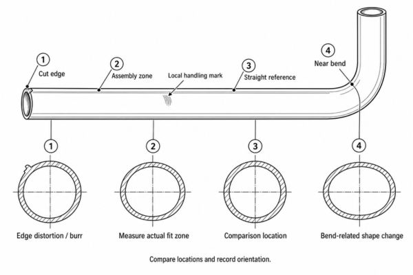
Compare controlled locations
Measure the location that actually enters or seals in the fitting, plus comparison locations defined by the inspection plan. Keep readings far enough from an irregular cut edge to avoid confusing a burr with the tube’s cross-section, unless the end itself is being inspected. Near a bend, follow the applicable specification because bend-related geometry may require a different evaluation from straight tube.
If the problem appears only at one short zone, document its length and relationship to tool marks, packaging contact, weld orientation, or impact. If directional variation repeats along the tube, preserve that pattern as evidence for material or manufacturing review. Do not infer the cause solely from the pattern; use lot, process, and handling records.
How Ovality Affects Insertion and Contact
Ovality changes both clearance and load distribution. The major diameter may create interference before the tube reaches its intended position, while the minor diameter can leave a different engagement condition around the circumference. Forcing the assembly does not restore the geometry assumed by the fitting design.
Insertion is only the first warning
A tube that will not enter freely may scrape against the nut, ferrule, ring, sleeve, or fitting bore. Scraping can create a surface path, move coating, generate particles, or damage the fitting component. Even if the tube eventually passes, the forced fit is not evidence that the completed connection will seal or retain correctly.
Conversely, a tube may enter because the fitting clears the major diameter but still contact unevenly during assembly. A ring or ferrule may engage differently around the circumference, and a formed end may become eccentric. Final acceptability must come from the specific fitting procedure and inspection criteria, not from insertion alone.
Do not reshape by improvisation
Hammering, squeezing in a vise, rolling by hand, or using the fitting to round the tube introduces uncontrolled deformation. These actions may change wall thickness, surface condition, material response, and cleanliness while leaving no approved basis for acceptance. Rework is permitted only when a controlled engineering procedure defines the method, limits, reinspection, and traceability.
Use Records to Establish the Acceptance Criterion
The tube purchase specification should identify applicable OD and shape requirements, while the fitting manufacturer may impose additional restrictions for its connection. The equipment drawing or fabrication specification can narrow them further. Use the most relevant current controlled requirement and resolve conflicts formally.
Evidence and its limits
A material certificate can help link the tube to a grade, condition, and lot, but it usually does not prove the measured ovality of every delivered location. A supplier inspection report is useful only when its sampling, method, results, and lot linkage are clear. Your own receiving or fabrication measurements establish sampled geometry, not universal conformity of unmeasured tube.
When documents disagree, do not choose the widest tolerance for convenience. Record the specification names and revisions, quarantine affected material as required, and ask the technical owner to determine which requirement governs. Product-specific acceptance cannot be transferred from a different tube material, wall, fitting series, or application.
Hypothetical Investigation of a Tight Assembly
Consider an explicitly hypothetical batch in which several tube ends resist entry into a fitting nut. The nominal tube markings match the purchase description, and photographs show no obvious large burr. An operator reports that rotating a tube changes where it binds, but no directional measurements have been recorded.
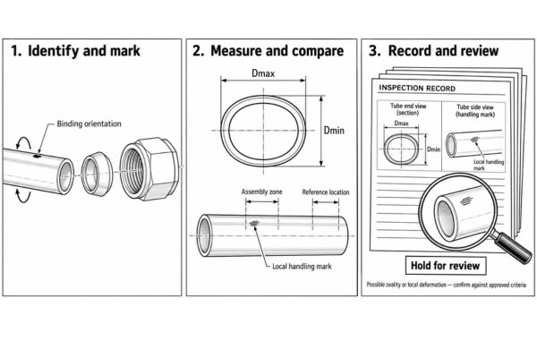
Evidence-based next steps
The quality team isolates the parts and verifies the nut and ring part numbers before blaming the tube. It marks the binding orientation, then measures the tube OD in several directions at the intended assembly zone and at comparison locations. The team records a maximum-to-minimum pattern at the binding zone, along with a local handling mark.
This evidence supports an oval or locally deformed condition as a candidate cause, but it does not prove how the deformation occurred or whether the lot must be rejected. The team compares results with the controlled tube and fitting criteria, reviews packaging and cutting records, and asks the authorized owner for disposition. It does not force, hammer, or manually round the tubes.
Mistakes That Hide the Real Condition
Common mistakes include measuring only once, averaging away the extremes, measuring directly over a burr, or comparing with nominal OD rather than the controlled tolerance. Another is diagnosing from a photograph; perspective and lighting cannot establish the cross-sectional dimensions. Using a ring or fitting body as a force-fit gauge can damage both parts.
When further review is necessary
Escalate when there is no approved ovality criterion, the fitting and tube requirements conflict, or measurements depend strongly on location. Also stop when the tube is near a bend, coated, visibly welded, locally damaged, or too flexible for a reliable method without special support. A repeated lot pattern, unexplained surface change, or prior forced assembly also requires broader review.
Before release, confirm:
- Exact tube, lot, material, condition, OD, wall, and fitting system
- Safe removal and preserved as-found condition
- Multi-direction readings at the actual assembly zone and defined comparison locations
- Separate records for burrs, coating, weld features, dents, scratches, and handling marks
- Instrument, calibration, method, contact-force control, and measurement orientation
- Current tube and fitting acceptance criteria, document revisions, reviewer, and disposition
If the available evidence cannot separate ovality from another cause, keep the diagnosis open. The goal is a reproducible measurement record, not a quick label.
Conclusion
Hydraulic tube ovality can block insertion and disturb circumferential contact even when the nominal OD appears correct. Diagnose it with multiple directional readings through the same cross-section, then repeat measurements at the actual assembly zone and controlled comparison locations. Keep burrs, coating buildup, weld features, wrong OD, fitting mismatch, and handling deformation as separate possibilities. Do not average away maximum and minimum readings, approve a tube from photographs, or force it through fitting components. Compare the preserved measurements with the current tube specification and the exact fitting system’s acceptance criteria; escalate conflicting or missing requirements. A documented, location-specific review provides the evidence needed to disposition hydraulic tube ovality without damaging parts or masking the original condition.
Frequently Asked Questions
Can hydraulic tube ovality be confirmed with a photograph?
No, a photograph cannot establish cross-sectional diameter variation. It can document visible deformation or handling marks, but calibrated multi-direction measurements are required for dimensional evaluation.
Is the average OD enough to accept an oval tube?
No, an average can hide an excessive maximum and insufficient minimum dimension. Record the directional readings and compare the relevant extremes with the approved acceptance method.
Should I measure directly at the cut edge?
Only when the controlled procedure calls for that location. A burr or cut distortion can bias the result, so preserve the edge evidence and measure at defined locations appropriate to the diagnosis.
Can I squeeze an oval tube round before assembly?
Not without an approved rework procedure and reinspection criteria. Uncontrolled reshaping can change wall, surface, material response, cleanliness, and traceability.
Does easy insertion prove the tube is round enough?
No, easy insertion only shows that gross interference did not occur in that trial. Final acceptance still depends on measured geometry, surface condition, correct components, and the fitting system’s assembly criteria.