A 37 degree tube flare inspection should reject or hold any flare with cracks, unacceptable surface damage, incorrect controlled geometry, eccentric forming, poor tube preparation, or an incompatible or damaged mating seat. Appearance alone cannot approve the connection, and tightening is not an inspection method. The flare must be evaluated with the current drawing, the exact fitting system’s instructions, and the gauges or measurement methods specified for that system.
Define the Flare and Its Acceptance Basis First
The inspection begins by confirming that the part is actually intended to use a 37-degree flared tube connection. Similar-looking flare systems exist, and thread engagement or a familiar nut does not establish the seat angle. Identify the fitting family, tube size and material, sleeve, nut, mating seat, and controlled drawing before deciding which criteria apply.
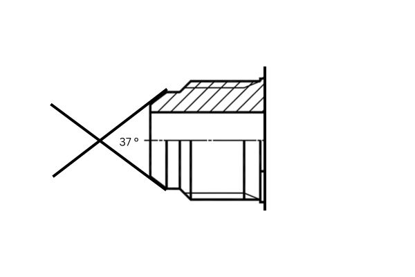
A flare is one part of a complete interface
The tube flare contacts a mating seat and is retained by the associated nut and sleeve or other system-specific components. Its acceptability therefore depends on more than the visible lip. Tube OD, wall, material condition, hardness, end preparation, forming process, surface quality, concentricity, flare geometry, and mating component condition all affect the completed connection.
Do not transfer criteria from a different product family merely because both are described as 37-degree systems. The approved flare diameter range, gauge, preparation, inspection method, assembly procedure, and reuse policy belong to the exact system and revision. If those records are missing, the correct disposition is review, not approval by experience.
Separate identification from tightening
Generic JIC identification determines connection features such as thread, gender, and seat form; flare inspection asks whether a prepared tube end is acceptable for its specified connection. Tightening then assembles approved components according to the applicable procedure. More torque cannot repair a cracked, eccentric, undersized, oversized, contaminated, or scratched flare.
Prepare the Part and Evidence Safely
Inspecting an installed flare may require opening a hydraulic connection. Stop the equipment, isolate the circuit, release pressure and stored energy, secure suspended loads, and follow the equipment manufacturer’s lockout and service procedures before loosening anything. Never feel for a leak or use disassembly as a diagnostic step on a live system.
Preserve the as-found condition
Photograph the connection before disassembly, including tube routing, support, alignment, and any leakage or movement evidence. Protect customer identifiers and record only the equipment information needed for technical traceability. After authorized removal, cap open lines and clean the flare using a method that does not polish away cracks, embedded particles, witness marks, or surface damage.
Collect these inputs before inspection:
- Tube and fitting part numbers, material descriptions, lot or fabrication records, and drawing revisions
- Exact 37-degree fitting system, nut and sleeve identity, and applicable assembly instructions
- Tube OD, wall, condition, forming tool, tool setup, lubrication, and preparation record where controlled
- Approved flare gauges, measurement method, dimensional criteria, and instrument calibration status
- Mating seat identity, surface condition, alignment, and prior assembly history when available
- As-found photographs, leakage location, tube support, routing, vibration, and maintenance notes
Missing history does not automatically reject a flare, but it limits the conclusions available. Record the evidence gap and use the controlled inspection plan to determine whether measurement, engineering review, or replacement is required.
Inspect Cracks and Surface Quality
Any suspected crack is a serious finding because the flare is a formed pressure-boundary feature. Visual inspection should use adequate lighting and magnification specified by the procedure, but uncertain indications may require an approved examination method. Do not scrape, bend, or dye a part informally to decide whether a line is a crack.
Look at both sides and the transition
Inspect the sealing face, outside surface, edge, inside surface, and transition from the original tube wall into the flare. Cracks may begin at an edge, tool mark, burr, or highly deformed area. Also look for splits, laps, folds, embedded chips, pits, scratches, scoring, galling, dents, corrosion, and contamination that crosses or interrupts the intended contact path.
The significance of a mark depends on its location, direction, depth, and the governing acceptance criterion. A circular witness mark from normal contact is not automatically a defect, while a radial scratch can create a path across a sealing band. Do not invent a permissible scratch size; compare the indication with the controlled drawing and inspection standard.
Connect defects to preparation evidence
Poor cutting and deburring can leave raised material that becomes embedded during flaring. Dirty or damaged tooling can transfer marks, while an unsuitable tube condition can contribute to tearing or cracking. These are investigation leads, not conclusions. Preserve the flare and tool condition, then review process records and comparison samples.
Check Geometry, Diameter, and Eccentricity
A visually smooth flare can still be dimensionally unacceptable. Inspection should verify the controlled outside diameter or gauge relationship, angle or profile as required, concentricity, squareness, and wall condition. Use the method named by the exact fitting system rather than estimating angle from a photograph.

Underflare and overflare risks
An underformed flare may provide insufficient intended contact or allow the mating nose to load the tube incorrectly. An overformed flare can interfere with the nut, sleeve, insert, or surrounding geometry and may show an unacceptable lip or thinning. The acceptance boundaries must come from the current drawing, gauge instruction, or manufacturer procedure.
Measure from defined datums and avoid using a damaged sleeve as the only gauge. If the system permits its sleeve to be used as a quick check, follow that exact documented method and confirm the sleeve identity and condition. A quick gauge does not replace other required surface, angle, concentricity, or material checks.
Eccentricity changes contact
An eccentric flare is not centered or uniformly formed around the tube axis. It may show an uneven rim, variable contact band, tilted face, or unequal relationship to the sleeve. Possible contributors include an angled cut, poor clamping, tube ovality, off-center tooling, misalignment, or uneven forming, but measurement and process evidence are needed before assigning cause.
Inspect the unflared tube near the flare for ovality, wall eccentricity, clamp damage, and bending stress. Check that the flare is at the required relationship to the tube axis using the approved gauge or fixture. Do not attempt to correct eccentricity by tightening the connection into alignment.
Follow a Controlled Inspection Sequence
A fixed sequence prevents an obvious surface mark from distracting the inspector from identity or geometry. It also makes results comparable across operators and lots. Each step should end in accept, reject, or hold-for-review according to the approved plan.
Sequence from identity to disposition
- Confirm identity. Match the tube, fitting, nut, sleeve, material, size, drawing, and procedure revisions.
- Review preparation. Verify cut, deburr, cleanliness, tube condition, and the specified flaring process and tooling.
- Clean and view. Inspect all flare surfaces and the transition for cracks, burrs, scratches, pits, folds, contamination, and corrosion.
- Check geometry. Apply the approved gauge or measurement method for flare diameter, profile, concentricity, squareness, and other controlled characteristics.
- Inspect the mating seat. Check identity, angle or profile, cleanliness, damage, corrosion, and alignment without assuming the flare caused every mark.
- Compare evidence. Review readings and observations against current criteria and record each nonconformity separately.
- Disposition and trace. Identify the reviewer, decision, rework or replacement instruction, and affected lot or assembly records.
If the inspection requires a specialized gauge, examination technique, or competence that is unavailable, stop at the evidence boundary. Do not substitute a protractor, photograph, improvised template, or trial tightening unless the approved procedure explicitly permits it.
Use a Defect, Evidence, and Disposition Table
The table organizes observations without assigning a cause too early. Final disposition still follows the exact drawing and quality plan. “Hold” means the part is not approved for assembly until the named evidence is reviewed.
| Finding | Evidence to record | Typical controlled disposition question |
| Suspected crack or split | Location, direction, magnified image, approved examination result | Does the criterion require rejection or further qualified examination? |
| Scratch, pit, or embedded burr | Position relative to sealing path, surface record, tool condition | Is the sealing surface interrupted beyond the allowed condition? |
| Flare diameter outside gauge relationship | Gauge identity, reading, sleeve identity, drawing revision | Is the flare underformed, overformed, or measured by the wrong method? |
| Eccentric or tilted flare | Orientation, rim variation, alignment check, tube condition | Does geometry meet the controlled concentricity and squareness criteria? |
| Uneven wall or internal lip | Section evidence if authorized, process record, tool setup | Is thinning or folding acceptable for this system? |
| Damaged mating seat | Seat images, profile check, part identity, prior history | Must the seat be replaced or separately evaluated before flare approval? |
| Contamination or corrosion | Material identity, residue location, cleaning history | Can approved cleaning restore the surface, or is damage present? |
Do not combine findings into a vague note such as “flare bad.” Specific records help determine whether the problem is isolated, process-related, lot-related, caused during assembly, or connected to a damaged mating part.
Hypothetical Flare Review
Consider an explicitly hypothetical tube assembly returned with evidence of leakage at a flared connection. The flare looks generally smooth in a front photograph, but the as-found tube was side-loaded and the mating seat has a visible mark. No current flare-gauge record accompanies the assembly.
What can and cannot be concluded
The team cannot approve the flare from the photograph or blame it for the leakage. After safe isolation and authorized disassembly, inspectors preserve the orientation, clean the interface, confirm component identities, and inspect both the flare and seat. They find a radial surface line on the flare and an off-center contact pattern, then place the parts on hold for the approved surface and geometry checks.
If the line is confirmed unacceptable or geometry falls outside the controlled criteria, the flare is rejected according to the plan. If the flare conforms, the damaged or misaligned mating seat and tube support still require disposition. The investigation records the evidence without inventing a torque, dimension, or product approval.
Avoid Shortcuts and Close the Inspection Record
Common mistakes include approving a flare because it is shiny, calling every circular mark damage, measuring with an unknown sleeve, or tightening until leakage stops. Another error is inspecting only the tube while ignoring a mismatched, contaminated, cracked, or scored seat. Reusing suspect components can erase evidence and repeat the failure.
Final checklist and escalation points
Escalate when part identity is uncertain, drawings conflict, the gauge is unavailable, a crack indication is ambiguous, or the mating seat cannot be inspected. Also request review for repeated defects, unexplained eccentricity, tube material outside the flaring requirement, damaged tools, or any proposed rework not covered by a controlled instruction.
Before release, confirm:
- Correct 37-degree system, tube, nut, sleeve, fitting, and mating seat identities
- Current drawing, gauge instruction, assembly procedure, and acceptance revision
- Clean surfaces inspected for cracks, burrs, scratches, pits, folds, corrosion, and contamination
- Controlled flare diameter, profile, concentricity, squareness, and wall-condition checks
- Tube preparation, material condition, ovality, tool condition, and alignment evidence
- Recorded decision, reviewer, affected lot or assembly, and approved next action
A complete record supports repeat production and troubleshooting. If a characteristic that controls sealing remains unresolved, the flare remains unapproved.
Conclusion
A reliable 37 degree tube flare inspection combines identity, surface examination, controlled geometry checks, and mating-seat review. Inspect every flare surface and transition for cracks, burrs, scratches, pits, folds, contamination, and corrosion, then verify diameter, profile, concentricity, and squareness with the approved drawing and gauge. Keep tube preparation, material condition, ovality, tooling, alignment, and seat damage in the investigation without assigning cause prematurely. Never approve a flare from appearance, trial tightening, or an improvised dimension, and never open a live hydraulic connection for inspection. Record each defect and its evidence separately, then use the current system-specific acceptance criteria for disposition. This disciplined approach identifies an unacceptable flare while preserving the facts needed to prevent recurrence.
Frequently Asked Questions
Can a smooth-looking flare still be unacceptable?
Yes, a smooth flare can have incorrect diameter, angle, concentricity, wall condition, or alignment. Visual quality is only one part of the controlled inspection.
Does a leak prove the 37-degree flare is defective?
No, leakage can involve the flare, mating seat, alignment, component mismatch, contamination, assembly procedure, or another system condition. Inspect the complete interface before assigning cause.
Can the tube sleeve be used as a flare gauge?
Only when the exact fitting system’s current instructions authorize that method. Confirm the sleeve identity and condition, and complete every other required surface and geometry check.
Can extra tightening correct an underformed flare?
No, tightening is not an approved way to reform or validate the flare. Use the specified forming process and reject, rework, or replace the part only through a controlled procedure.
Should a suspect flare be reused after inspection?
Only when the applicable procedure and authorized reviewer approve reuse after all criteria are met. Cracked, damaged, contaminated, or unresolved parts should remain out of service pending disposition.