Identifying the correct thread and seat combination requires direct physical measurement with a caliper and thread gauge rather than relying on missing manufacturer part numbers. When a high-pressure hose bursts on a heavy excavator mid-shift, production halts completely, costing hundreds of dollars per hour while your mechanics stare at a stripped, unidentifiable fluid connector. Without an OEM part number stamped on the hex flat, ordering a replacement becomes a high-stakes guessing game that often leads to fluid leaks, cross-threaded ports, or catastrophic fitting blowouts under full system pressure. By executing a precise, step-by-step physical inspection of the thread profile, pitch, and sealing seat angle, you can confidently determine the exact specification needed to get your machinery back into operation.
Why Do OEM Codes Disappear From Hydraulic Components?
The primary reason part codes become unreadable is severe operational abrasion combined with surface oxidation over hundreds of hours of equipment exposure.
When fluid connectors are exposed to high-vibration environments, metal-on-metal rubbing quickly grinds away shallow laser-etched markings.
What Environmental Factors Accelerate Marking Degradation?
Corrosive environments rapidly destroy any surface-level identification markers left by the original manufacturer. Extended exposure to UV rays, salt spray, and caustic hydraulic fluids will pit the carbon steel hex surfaces, leaving nothing but a layer of rust where the part number used to be.
- Continuous exposure to chemical degreasers strips away paint coatings.
- Constant exposure to abrasive gravel blast wears down raised stampings.
- High thermal cycling oxidizes protective zinc-nickel platings over time.
Can Operational Vibration Destroy Laser Etchings?
High-frequency system pulses cause structural components to rub continuously against adjacent lines, polishing out laser-etched text. This mechanical friction makes routine field identification nearly impossible during an emergency breakdown.
- Hose-to-hose rubbing removes outer sleeve print bands.
- Frame-contact vibration grinds down metal hex points.
Using heavy-duty protective sleeving prevents this physical wear, preserving critical component markings for future maintenance intervals.
| Degradation Mechanism | Impact Severity | Primary Preventive Measure |
| Mechanical Abrasion | High Risk | Install textile protective hose sleeves |
| Chemical Oxidation | Medium Risk | Upgrade to high-zinc plating specifications |
What Tools Are Required For Accurate Thread Identification?
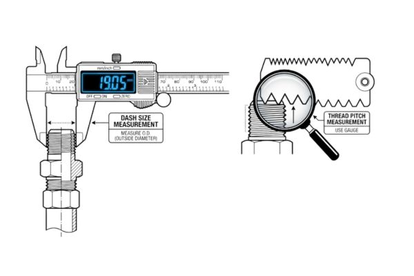
Accurate identification demands a precise digital caliper, a pitch gauge set, and a specialized seat angle gauge. You cannot rely on a standard tape measure or a simple visual estimation because a fraction of a millimeter difference will cause a catastrophic thread strip or high-pressure bypass leak when you master how to match hydraulic fittings in the shop.
Why Is A Digital Caliper Essential For O.D. Measurements?
A digital caliper allows you to measure both the outer diameter of male threads and the inner diameter of female connections down to two decimal places. This level of precision is necessary because standard metric and imperial fractional sizes look nearly identical to the naked eye.
- It eliminates parallax errors inherent in manual rulers.
- It captures true peak-to-peak dimensions across thread crests.
- It enables instant switching between metric and decimal inch scales.
How Does A Thread Pitch Gauge Eliminate Guesswork?
A pitch gauge set contains multiple precision-cut teeth profiles that lock directly into the valleys of your existing threads to determine the exact spacing. Trying to count threads over a quarter-inch section manually introduces unacceptable errors that lead to component damage.
- It verifies the exact number of threads per inch for imperial fittings.
- It determines the precise millimeter distance between metric thread crests.
Investing in a dedicated fluid power measurement kit saves hours of trial-and-error assembly work while ensuring perfect connection integrity.
| Identification Tool | Required Accuracy | Critical Measurement Function |
| Digital Caliper | +/- 0.01 mm | External crest and internal root diameters |
| Pitch Gauge Set | Nominal fit | Individual thread-to-thread distance verification |
How Do You Determine If A Thread Is Metric Or Imperial?
You determine the thread standard by measuring the outside diameter and checking if the pitch perfectly matches metric or imperial gauge profiles.
If the dimensions align with clean millimeter increments, you are likely dealing with a metric DIN or ISO connection rather than an American standard.
What Metric Standards Dominate Modern Equipment?
Metric threads are predominantly categorized into DIN 2353 light or heavy series and French GAZ standards, which are widely utilized in European machinery. These connectors feature pitch values defined by the absolute distance between threads in millimeters, such as 1.5mm or 2.0mm.
- DIN threads feature a sixty-degree included thread angle profile.
- Metric threads use outer diameters like twenty-four or thirty millimeters.
- GAZ fittings utilize a twenty-four-degree cone seat configuration for sealing.
How Do You Identify American Standard Threads?
American hydraulic systems rely on National Pipe Tapered or Joint Industry Council standards, where pitches are calculated by counting threads per inch. For instance, a standard half-inch JIC fitting always features fourteen threads per inch, which will not match any metric pitch pattern.
- UN/UNF threads feature a sixty-degree thread profile angle.
- NPT threads use a tapered profile to achieve a mechanical seal.
Recognizing whether your machine uses European metric or American imperial standards immediately narrows down your replacement options by half.
| Thread Family | Pitch Unit | Common Seat Angles |
| Metric (DIN/ISO) | Millimeters (mm) | 24, 60 degrees |
| Imperial (UNF/NPT) | Threads Per Inch (TPI) | 37, 45 degrees |
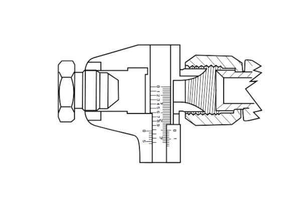
How Do You Measure Tapered Versus Parallel Threads?
You distinguish tapered from parallel threads by taking outer diameter measurements at both the front crest and the back flat of the thread section.
How Do You Detect A Thread Taper Safely?
To identify a taper, measure the thread diameter at the very first pin crest, then take a second measurement at the base hex shoulder. If the caliper reading increases significantly from front to back, you are working with a tapered fitting like NPT or BSPT.
- Tapered threads exhibit a visible dimensional slope along the length.
- They wedge tightly together as they are threaded into a port.
- They require thread sealant or PTFE tape to prevent helical leakage.
What Indicates A True Parallel Thread Geometry?
Parallel threads maintain a completely uniform outer diameter across the entire length of the male connector. If your caliper shows identical values at the nose and the hex base, it is a straight thread that requires an auxiliary sealing element.
- Straight threads require a back-up washer or elastomeric O-ring.
- They allow the fitting to bottom out completely inside the port.
Understanding this dimensional geometry prevents you from over-tightening straight threads into tapered ports, which fractures heavy cast manifolds.
| Thread Profile Type | Diameter Variance | Required Sealing Mechanism |
| Tapered | Varies from front to back | Thread sealant or metal deformation |
| Parallel | Uniform across entire length | O-ring, bonded washer, or soft seal |
What Is The Step By Step Caliper Measurement Workflow?
The correct workflow requires wiping the thread completely clean of fluid, zeroing your caliper, and measuring across the widest point of the thread crests.
Any residual grease or metal burrs left on the component will throw off your reading by crucial fractions of a millimeter.
Where Should You Place The Caliper Jaws?
Place the flat section of the caliper jaws squarely across the outer peaks of the male thread, ensuring the instrument is perfectly perpendicular to the fitting centerline. For female ports, insert the internal measurement tips deeply into the opening to capture the absolute minimum root diameter.
- Avoid placing tips on damaged or cross-threaded entry sections.
- Take multiple readings at ninety-degree angles to check for roundness.
- Keep the caliper clean of abrasive grit to maintain accuracy.
Why Must You Zero Your Tool Before Measuring?
Failing to zero your tool can introduce a persistent calibration error that misleads you into selecting an incorrect size class altogether. Always close the jaws completely and hit the clear button before touching the metal component.
- Zeroing compensates for temperature-induced structural expansion of the jaws.
- It ensures consistency across different shifts and technicians.
Following this disciplined measurement routine eliminates human error and guarantees highly repeatable field data collection.
| Component Face | Measurement Target | Caliper Jaw Position |
| Male Fitting End | Maximum Outer Diameter | External flat jaws across crests |
| Female Component Port | Minimum Inner Diameter | Internal pointed tips inside root |
How Do You Determine The Exact Thread Pitch Value?
You find the pitch value by pressing individual gauge blades into the thread profile until you find one that seats cleanly without showing any visible daylight gaps.
How Do You Spot A Perfect Gauge Match?
A perfect match occurs when the teeth of the pitch blade engage fully into the valleys of the thread without rocking or leaving open gaps. If the tool rocks back and forth when pressed down, the pitch is incorrect and you must try an alternative blade size.
- The gauge must sit completely flat against the threaded cylinder.
- The tooth spacing must match both the start and end threads.
- No light should shine through the interface when held to a lamp.
What Happens If You Mix Metric And Imperial Pitches?
Forcing a metric fitting into an imperial port will strip the threads instantly as soon as torque is applied with a wrench. The initial turn may feel smooth, but the mismatch will bind up quickly and ruin the expensive mating component permanently.
- It creates localized stress concentration zones that fracture under pressure.
- It destroys the thread crests, causing immediate fluid bypass.
Taking an extra sixty seconds to verify the pitch using a dedicated gauge set prevents catastrophic component failure in the field.
| Pitch System | Key Indicators | Common Tool Settings |
| Metric Series | Expressed as millimeters per thread | 1.0, 1.5, 2.0 mm profiles |
| Imperial Series | Expressed as total threads per inch | 12, 14, 16, 18 TPI profiles |
How Do You Identify Sealing Seats And Cone Angles?
You identify the sealing seat by measuring the angle of the machined chamfer relative to the centerline of the fluid connector.
The thread itself does not hold back the high-pressure fluid; it merely acts as a mechanical fastener to clamp the internal sealing faces together.
What Are The Most Common Sealing Angles Found?
The most widespread industrial configurations are the thirty-seven-degree JIC flare, the forty-five-degree SAE flare, and the twenty-four-degree DIN cone seat. If you mix up a thirty-seven-degree fitting with a forty-five-degree mating seat, the line contact will crush unevenly and leak instantly.
- JIC fittings utilize a thirty-seven-degree angle on male and female faces.
- BSPP fittings commonly incorporate a sixty-degree inverted cone seat design.
- DIN connections rely on a twenty-four-degree cone with an integrated rubber ring.
How Can You Measure Seat Angles Accurately?
Use a specialized pocket seat angle gauge or an angle protractor kit placed directly against the machined sealing surface to read the slope angle. If no gauge is available, visually compare the angle against a known standard fitting profile under bright workshop lighting.
- Inspect for pitting or deep score marks across the seating face.
- Ensure the nose cone is not deformed from historic over-tightening.
Identifying the exact seat angle prevents you from assembling components that look tight but lack a continuous physical sealing boundary.
| Common Standard | Machined Seat Angle | Primary Sealing Method |
| JIC Standard | 37 Degrees | Metal-to-metal mechanical flare |
| BSPP Series | 60 Degrees | Inverted cone seat line contact |
How Do You Cross Reference Captured Dimensions With Standards?
You cross-reference your measured diameter and pitch by looking them up in standard fluid power dimension tables found in industrial reference manuals.
A measured outer diameter of twenty-six point four millimeters does not mean you order a twenty-six millimeter fitting; it actually translates directly to a standard G three-quarter BSP thread size.
How Do You Use An Industrial Thread Dimension Chart?
Locate your calculated outer diameter on the chart within the corresponding metric or imperial column, then verify that your pitch reading matches the value listed on that same row. This lookup step confirms the official trade size name of the component you need to purchase.
- Look for exact nominal diameter ranges rather than absolute precision numbers.
- Cross-check both male and female dimension columns to confirm fit.
- Double-check standard system tolerances allowed by international norms.
What Are The Risks Of Out Of Spec Measurements?
Component wear or heavy structural stretching can cause your physical measurements to fall completely between standard chart values. When this happens, inspect the equipment for hidden deformation or look for a secondary mating component to re-verify the baseline geometry.
- Stretched threads indicate imminent material yield failure.
- Distorted hex flats suggest historical over-torque abuse by mechanics.
Using a verified industrial reference table bridges the gap between raw shop dimensions and accurate commercial part descriptions.
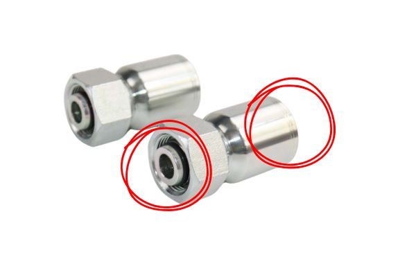
How Do You Verify O Ring Face Seal Fittings?
You verify an O-ring face seal fitting by measuring the outer diameter of the straight thread and checking the machined groove on the flat nose face.

What Makes ORFS Connections Unique?
ORFS fittings seal when an elastomeric O-ring embedded in the face of the male connector is compressed flat against the smooth sleeve surface of the female assembly. The straight threads serve purely to generate the high clamping force required to squeeze this rubber seal into its groove.
- They completely eliminate the weeping leaks common in metal seats.
- They handle high-vibration system pulses without loosening over time.
- They allow for easy slip-in installation without spreading adjacent piping.
How Do You Measure An ORFS Grooved Face Properly?
Measure the absolute outer diameter of the male straight threads to determine the frame size, then check that the rubber O-ring fits completely flush inside its retaining groove. If the groove wall is nicked or distorted, the fitting must be discarded immediately to prevent seal blowout.
- Check that the rubber material matches your system fluid chemistry.
- Verify the O-ring thickness matches the machined groove depth perfectly.
Replacing worn elastomeric seals during every component rebuild keeps your high-pressure lines operating at maximum safety margins.
| ORFS Dash Size | Thread Specification | O-Ring Inner Diameter |
| Dash 04 | 9/16-18 Straight UN | 7.65 mm standard profile |
| Dash 08 | 13/16-16 Straight UN | 12.42 mm standard profile |
Maintaining these precise elastomer boundaries prevents sudden high-pressure fluid leaks across your critical control valves.
What Are Common Identification Pitfalls To Avoid?
The most dangerous pitfall is confusing British Standard Pipe threads with American National Pipe threads because their pitches and profiles are almost identical to the eye. For example, a half-inch BSP thread features fourteen threads per inch, while a half-inch NPT thread features fourteen threads per inch as well, but their thread pitch angles differ by five crucial degrees, making them completely incompatible.
Why Is Visual Estimation A Recipe For Failure?
Relying on your eyesight to differentiate between similar international profiles leads to cross-threaded assemblies that fail violently under load. A metric M22 thread and a seven-eighths inch UNF thread look identical across the shop floor but will destroy each other if forced together with an impact wrench.
- Visual matching ignores tiny pitch differences that cause thread binding.
- It overlooks subtle seat angle variations that create micro-leaks.
- It often leads to ordering incorrect parts, increasing machine downtime.
How Can Component Wear Distort Your Readings?
Fittings that have been subjected to extreme pressure spikes or repeated maintenance cycles will experience physical deformation that alters their nominal dimensions. Always measure clean, un-deformed sections of the component to get the most accurate baseline data.
- Thread crests flatten out over years of high-torque service.
- Sealing seats develop deep grooves that mask the original angle.
Avoiding these common identification mistakes keeps your maintenance operation safe, efficient, and completely free of unexpected line leaks.
| Identification Mistake | Immediate Operational Consequence | Corrective Action |
| Visual Guesswork | Stripped threads and fluid leakage | Use calipers and pitch gauges every time |
| Mixing BSP and NPT | Incomplete engagement and blowouts | Check thread crest profile angle profiles |
Conclusion
Accurately matching high-pressure fluid connectors without original part codes is an entirely manageable engineering task if you substitute visual guesswork with disciplined physical measurement. By systematically deploying digital calipers, pitch gauges, and seat angle finders, you can decode any mystery thread profile and eliminate the risk of premature field failures or destructive oil leaks. This rigorous diagnostic process minimizes equipment downtime, protects your hydraulic system infrastructure, and ensures that every replacement component performs flawlessly under the most demanding operational loads. If you are struggling with unidentifiable connectors or need engineered fluid power components for your fleet maintenance, please contact us today to connect with our senior technical support team.
FAQ
Can I mix a BSPP male fitting with an NPT female port if the diameters feel close?
No, you cannot mix them because they feature completely different thread forms and pitch angles that will not seal safely. BSPP uses a fifty-five-degree thread angle, while NPT relies on a sixty-degree angle, meaning they will cross-thread and leak immediately under fluid pressure.
What’s the best way to determine seat angle if I do not own an angle gauge?
The best approach is to utilize a known standard fitting reference as a direct physical comparison gauge under good lighting. Press the sealing faces of the unknown fitting and the reference fitting tightly together; any visible alignment gap indicates that their angles do not match.
How do I know if a thread is stretched and unsafe for rebuild assembly?
You can verify this by running a standard pitch gauge blade along the entire length of the engaged thread section. If the gauge teeth fit perfectly at the front but lift out completely near the back flat, the thread has stretched under excessive torque and must be scrapped.
Can I reuse elastomeric face seals when switching out old steel fittings?
No, you should always replace elastomeric seals with brand new ones during every component installation cycle. Used O-rings retain a permanent compression set and develop micro-fissures that fail rapidly when exposed to high system pressures.
What should I do if my caliper measurement falls directly between two standard sizes?
You should clean the component completely and measure a different, un-deformed section of the thread to rule out physical wear. If the reading remains between sizes, you are likely dealing with a proprietary manufacturer thread or a specialized international standard that requires direct factory support.