One-piece fitting clocking errors occur when two angled end fittings have the wrong relative rotational orientation around the hose centerline. Fitting angle describes the individual elbow shape, while clocking describes how one end is rotated compared with the other. Both fittings can have the correct thread, seal, dash size, bend angle, and drop length yet still fail to align with fixed machine ports. Trying to install a misclocked assembly can twist the hose, load the connections, violate the intended route, or make installation impossible.
Fitting Angle and Assembly Clocking Are Different
A 90-degree fitting turns its own centerline through a right-angle geometry; that is the fitting’s bend angle. Clocking compares the direction of one angled end with the direction of the other after both are attached to the same hose.
Imagine looking along the hose axis from one end. The first elbow points upward. The second elbow might point upward, sideways, downward, or somewhere between. That relative rotation is the clocking relationship. Changing it does not turn either 90-degree elbow into a different bend angle.
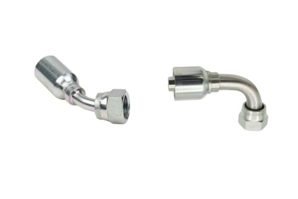
Separate angular orientation from fitting geometry
Drop length is another separate variable. It locates the hose centerline relative to the connection plane. An assembly can have correct clocking but wrong drop, or correct drop but wrong clocking. Troubleshooting should keep angular orientation, elbow angle, and linear offset in separate records.
Straight fittings usually do not establish a strong rotational direction unless they contain an orientation-dependent feature. This is why a straight-to-elbow assembly is generally less sensitive to relative clocking than an elbow-to-elbow assembly.
Define a Repeatable Angular Datum
Clocking cannot be inspected reliably from “looks about right.” The assembly drawing or work instruction needs a reference end, a viewing direction, a zero direction, and a defined feature representing each angled end.
A practical method designates one fitting as the reference and places its centerline or another controlled feature at zero. The second fitting is described by its rotation when viewed from a stated end. A clock-face description can communicate orientation visually, while a degree-based description can support measurement.
State reference end, view, and zero
For example, the reference elbow could be placed conceptually at twelve o’clock and the second described relative to it. This is only an illustration. Organizations can use different viewing directions, positive-rotation conventions, and datum features, so the actual drawing must state its convention.
Swivel nuts should not be mistaken for elbow-body orientation. A nut can rotate for connection while the stem or elbow direction remains the feature that establishes the hose route. Mark and measure the controlled body centerline, not a movable wrench flat unless the instruction defines it.
How Clocking Error Enters During Assembly
Clocking error is introduced when the second angled fitting is positioned or moves relative to the first before its orientation becomes fixed by crimping. Process controls should preserve a defined angular relationship through insertion, setup, and die closure.
The wrong drawing view or viewing direction can reverse the intended rotation. An operator can also reference an inconsistent feature, place the hose on a bench without controlling natural curvature, or align to a movable nut rather than the elbow centerline. Faint, misplaced, or ambiguous orientation marks can add variation.
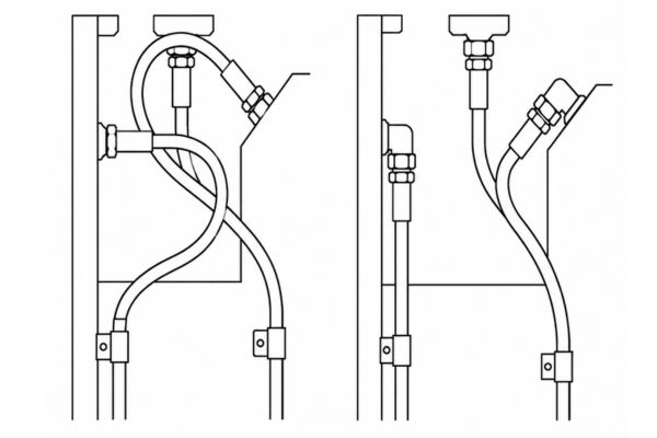
Control movement before the second crimp
Movement can occur while the assembly is transferred to the crimper or positioned in the dies. Hose stiffness and memory may rotate an unsupported end. If one end is crimped first, the hose can relax or roll before the second is fixed. Tooling clearance can also make visual alignment difficult.
The solution is not to hold the fitting by force during an improvised closure. Use the approved fixtures, references, marks, sequence, and inspection method for that assembly. Machine operation and crimping must follow current manufacturer data.
A Small Angular Error Becomes Hose Twist in Installation
Fixed ports demand that both ends arrive at specific positions and orientations. If the second end is rotated from that relationship, installers may try to twist the hose body until the connection faces the port.
Twist distributes torsion along the hose and changes reinforcement geometry. It can also shift the natural bend plane, pull the hose against guards, or add side load to fitting connections. The assembly may look connected while carrying stored installation strain.
Installation converts angle into torsion
The visible rotation at the fitting can appear small, yet its practical effect depends on hose length, stiffness, routing, end geometry, and port constraint. No universal angular error can be declared harmless. A short, stiff assembly between fixed ports may react strongly, while a longer route may visually absorb rotation but still retain undesirable torsion.
Do not use hose flexibility as permission to compensate. Hose should be routed without twist according to manufacturer instructions. If ends do not align in a relaxed state, stop, verify the assembly drawing and measurements, and evaluate remake or approved disposition.
Double-Elbow Assemblies Are More Clocking-Sensitive
Two angled ends each create a directional vector, so their relative rotation directly controls whether both connections can meet their ports. A straight end has no comparable elbow direction, making straight-to-elbow assemblies less constrained in this specific way.
| Assembly type | Clocking sensitivity | Verification point |
| Straight to straight | Usually low unless other orientation features exist | Finished length, connection details, and any keyed feature |
| Straight to elbow | One primary angled direction controls routing | Elbow orientation relative to the assembly or installation datum |
| Elbow to elbow | High because both directions form a relative angular pair | Reference end, viewing direction, and second-end rotation |
| Two elbows with different drop lengths | Angular and linear geometry interact | Clocking plus each tangent point and installed envelope |
| Two elbows in a short stiff assembly | Small mismatch may create strong installation reaction | Relaxed bench orientation and fixed-port alignment |
Relative direction controls the two-end fit
Two 90-degree fittings can be intended to lie in the same plane, face opposite directions, or occupy different planes. Their individual bend labels do not reveal which arrangement is correct. The assembly drawing must carry that information.
A 45-degree and 90-degree combination is also clocking-sensitive. Their centerlines are different, but both define direction. Inspection should reference the intended outgoing centerline of each end rather than comparing body edges that may not be parallel.
Hose Length and Stiffness Change Severity
Clocking error is angular, but the resulting installation strain depends on the flexible section between the ends. Length, construction, diameter, reinforcement, temperature, and natural curvature influence how the hose reacts.
A short assembly has little flexible distance over which rotation can appear, so misalignment may prevent the nuts or flanges from reaching their ports. A long assembly may allow the end to be rotated into place more easily, but that action can distribute twist invisibly along a broad curve.
Stiffer reinforcement or a large hose construction may resist torsion strongly. A more flexible hose can mask misclocking on the bench, especially if it is coiled or unsupported. Neither response proves acceptability. Compatibility and routing requirements remain specific to the hose and application.
Temperature can change flexibility during handling, but it does not correct orientation. Do not heat, torque, or mechanically preload an assembly to achieve alignment unless an approved procedure explicitly defines the condition. The installed hose should follow its intended relaxed route.

Why the assembly may look fine on the bench
A bench does not reproduce fixed port spacing, equipment obstacles, clamp positions, gravity direction, or motion envelopes. A misclocked assembly can roll, lift, or curve freely and appear normal until both ends are constrained.
Hose memory can rotate one elbow when the assembly is laid flat. An inspector may press both ends against the table and unintentionally force them into a common plane, hiding the natural relative orientation. Looking from an oblique angle can also create parallax and make clock-face comparisons unreliable.
Bench inspection should support the hose without imposing twist and use a defined reference fixture or measurement method. The reference fitting must be seated consistently, and the viewing direction must match the drawing. Record the relaxed condition rather than holding the second end at the desired angle.
Installation templates can help represent port geometry, but they need controlled dimensions and should not be treated as universal gauges for unrelated assemblies. Final fit should be evaluated under safe, depressurized conditions and without forcing the hose.
Control orientation before and after crimping
Clocking quality depends on controls before the angle is fixed and on an independent check afterward. The method should be repeatable across operators and clearly linked to the assembly drawing.
Before crimping, confirm both fitting identities, elbow angles, drop lengths, hose and fitting series, finished-length reference, and approved insertion. Establish the reference end and viewing direction. Apply orientation marks or use a fixture only as defined by the controlled process.
Support the hose so memory does not rotate an end during setup. After the first crimp, re-establish the datum before positioning the second fitting. Prevent movement during handling and die closure by the approved method, not by placing hands near operating dies.
After crimping, let the assembly rest in the defined inspection condition and measure relative orientation without twisting it. Verify finished length, drop-related envelope, insertion evidence, crimp dimensions, and connection identity separately. One correct clocking result does not approve those other characteristics.
Troubleshoot an Assembly That Will Not Align
When an assembly misses fixed ports, stop before applying torque through the hose. Isolate and depressurize equipment, release stored energy, secure raised loads, and follow lockout and manufacturer instructions before disconnecting or measuring.
First confirm the installation: correct ports, port spacing, route, clamps, equipment position, and original drawing revision. Check connection standards and sealing forms independently. Then place the assembly in a relaxed condition and compare finished length, each elbow angle, each drop length, and relative clocking from the specified datum.
Separate assembly error from installation error
If clocking is wrong, determine whether the error came from drawing interpretation, part identity, marking, fixture, movement before closure, or inspection method. Do not twist the hose to make it fit, rotate a non-swivel body by force, or re-crimp an existing end without an approved procedure.
Disposition may require remaking the assembly with verified components and process controls. Preserve the nonconforming assembly and records so the cause can be corrected. A remake should be checked against the same controlled angular and linear references before installation.
Record whether the mismatch appears at both ports or only after clamps are applied, because clamp position can expose a separate routing error that resembles clocking.
Conclusion
Clocking is the relative rotation between directional end fittings, not the bend angle of either fitting or its drop length. The error enters when the second end is referenced, marked, handled, or crimped in the wrong orientation, and fixed machine ports can convert that angular difference into hose torsion and connection strain. Double-elbow and short stiff assemblies are especially sensitive, while a flexible hose may hide the problem on a bench without making it acceptable. For one-piece fitting clocking errors, prepare the reference end, viewing convention, angular relationship, elbow and drop dimensions, hose and fitting identities, finished length, relaxed inspection evidence, and installed port geometry. Remake a misclocked assembly under approved procedures rather than twisting it into place.
FAQ
Is clock-face notation a universal hose clocking convention?
No, viewing direction and zero reference can differ. Every drawing or instruction must define its own convention before clock-face positions are compared.
Can two 90-degree fittings point in different planes intentionally?
Yes, many routes require different relative orientations. The correct relationship comes from the assembly drawing and installed port geometry, not the shared 90-degree label.
Can a flexible hose safely compensate for clocking error?
No, flexibility can hide distributed twist but does not prove an acceptable installation. The hose should align without torsional preload under manufacturer routing requirements.
How should fitting orientation be measured?
Use a defined reference end, viewing direction, zero feature, and controlled method that supports the hose without twisting it. Record the convention with the result.
Can a misclocked hose assembly be reworked?
Only an approved procedure and responsible technical authority can determine disposition. Do not twist, rotate by force, or re-crimp an end merely to change orientation.