Has your hydraulic fitting nut deformed, or has it simply stopped turning because the connection is fully seated? Resistance to rotation alone does not prove damage, as normal clamp load can hold the nut in place after tightening. Permanent changes in shape, distorted wrench flats, or binding before the sealing surfaces meet warrant closer inspection. Possible causes include mismatched mating parts, misalignment, dimensional errors, material condition, and differences in lubrication or coating. A recorded torque value alone cannot establish whether assembly was correct or explain why damage occurred. To identify the cause, compare the same hydraulic fitting assembly before tightening and after approved disassembly, using consistent measurements and the product-specific installation instructions rather than assuming excessive torque.
Decide Whether the Condition Is Restraint or Damage
The first decision is whether the nut changed permanently or simply stopped moving because the joint developed its intended clamp load. Testing “free rotation” while fully tightened confuses these conditions and can damage a correctly seated connection.
Normal restraint occurs after seating
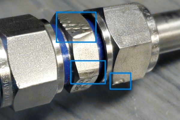
An assembly swivel nut is commonly intended to rotate during alignment and make-up, not to remain freely rotating under final clamp load. Once the sealing faces contact and the connection reaches its specified assembly condition, friction and axial load can restrain the nut. That behavior is different from a live swivel designed to rotate during service, and it is also different from a compression nut whose movement loads a ferrule or other component.
Identify the actual design before evaluating motion. Record whether the part is an assembly swivel, live swivel, compression connection, retained nut, or another configuration. Do not turn a post-tightening movement check into a universal acceptance rule; the applicable drawing and assembly procedure determine what motion is expected before, during, and after make-up.
Permanent deformation leaves measurable evidence
Permanent distortion remains after the load is removed under an authorized procedure. Possible observations include changed across-flats or across-corners dimensions, an out-of-round bore, displaced retaining geometry, cracked or flaked coating, thread damage, a visibly collapsed wall, or continued binding after cleaning and disassembly. Elastic response disappears when load is removed and should not be described as permanent deformation without a controlled comparison.
Do not straighten, squeeze, machine, or force a suspected nut back into service. Such actions destroy evidence and can create an unverified pressure-containing connection. If the fitting is installed, secure the equipment, support loads, isolate the hydraulic system, release stored energy, and follow the equipment procedure before examination.
Identify the Nut and Keep Tightening Separate From Crimping
Nut make-up and hose crimping are distinct processes. A crimper compresses the ferrule or shell according to a validated hose-and-fitting specification; a wrench applies torque or prescribed movement to the connection during installation.
Trace the complete assembly
Record the complete fitting part number, connection type, nut design, thread designation, sealing method, hose and fitting series when present, drawing revision, material and coating requirements, and the mating component. Similar-looking nuts may transfer load through different shoulders, retainers, bearing surfaces, seats, or ferrules.
Confirm whether the nut was supplied as part of a one-piece hose fitting, a separate tube fitting, an adapter, or another assembly. A one-piece hose fitting generally retains its stem and ferrule together, but this structure does not prove that any mating nut, hose, thread, or crimp specification is compatible. Do not use the same dash size as evidence that the components belong together.
Map the load path
The investigation should show where wrench input becomes axial clamp load and which surfaces react that load. Relevant interfaces may include the nut threads, male mating thread, nut shoulder, swivel bearing surface, flare or cone seat, compression ferrule, tube, retaining feature, and fitting body. A mismatch can concentrate load before the intended sealing surfaces seat.
Create an annotated section view or controlled sketch from the approved drawing. Mark the contact sequence expected during make-up. If the assembly binds before the intended seat contacts, the problem is not solved by applying more torque; the obstruction and geometry need investigation.
Reconstruct the Assembly Event Before Assigning Cause
A credible hydraulic fitting torque investigation needs more than the final tool reading. Torque is an input influenced by friction, tool setup, and procedure; it is not pressure and does not directly measure sealing contact or nut stress.
Confirm the actual instruction and conditions
Obtain the product-specific installation method for the exact connection and revision. It may specify torque, flats-from-wrench-resistance, a position-based method, or another sequence. Record thread and seat cleanliness, permitted lubrication or sealant, coating condition, alignment, hand engagement, wrench placement, backup-wrench use, tool extension, adapters, tightening speed, and whether the joint was new or previously assembled.
Do not transfer a torque from another size, material, coating, connection family, or manufacturer. Do not lower torque arbitrarily to avoid deformation. A lower value may leave an inadequately seated connection, while the actual problem—such as wrong mating geometry—remains.
Verify the tool result without overstating it
Check the torque tool identity, calibration status, range, units, setting method, adapter correction, and data record. Confirm that the measured event was connection tightening rather than breakaway or loosening torque. A peak reading may include binding, thread damage, or tool movement and does not by itself prove correct clamp load.
Preserve the assembly sequence:
- condition and dimensions before assembly;
- hand engagement and alignment observations;
- point of first resistance or specified reference position;
- applied method and tool configuration;
- any noise, sudden movement, coating disturbance, or binding; and
- condition after authorized disassembly and cleaning.
Compare Before and After With Controlled Measurements
Before-and-after data helps distinguish permanent change from normal seated restraint. Measurements must use consistent datums, equipment, temperature, orientation, and surface preparation.
Measure features that describe shape and function
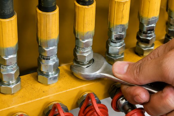
Depending on the approved inspection plan, compare across-flats, across-corners, bore roundness, thread condition, retaining geometry, nut length, shoulder position, and the clearance needed for swivel motion before seating. Inspect the mating thread, seat, and body at the same time because the nut may be responding to another component.
Use multiple orientations rather than one caliper reading. Wrench contact can raise local marks without changing the whole nut, and coating thickness can affect edge readings. Record measurement uncertainty near any limit. Do not invent a universal allowable dimensional change; acceptance must come from the drawing or approved engineering disposition.
Authorized disassembly protects evidence and safety
Disassembly may change contact marks, release elastic strain, or damage a connection intended for limited assembly cycles. Obtain approval before separating investigative samples, especially retained hose assemblies or installed parts. Identify which components may be reused, which must be quarantined, and which are destructive-analysis samples.
Photograph wrench flats, thread starts, nut face, shoulder, retainer, sealing surface, and mating part before cleaning. Then use the approved cleaning method and repeat inspection. Separate loose contamination, coating transfer, and base-metal deformation in the record.
Evaluate Assembly, Geometry, Material, and Change History
The symptom can have several interacting causes. Testing one explanation while ignoring the mating component or design revision can produce a false corrective action.
Assembly and mating conditions
Review cross-threading, insufficient hand engagement, angular misalignment, wrong mating thread, seat mismatch, bottoming, shoulder interference, damaged threads, trapped debris, prohibited sealant, lubrication difference, and incorrect wrench support. These conditions can raise resistance or redirect load before proper seating.
Thread identity alone is insufficient. Confirm diameter, pitch, straight or tapered form, male and female class or tolerance where applicable, seat angle, sealing face, and contact location. A nut may engage a wrong component far enough to appear plausible while transferring load through an unintended surface.
Component and design conditions
Compare controlled dimensions for the nut, body, retainer, mating part, and seat. Review material specification, heat treatment or hardness evidence when applicable, wall sections, transition radii, coating, and manufacturing records without assuming any is the cause. A material certificate alone does not prove final geometry or assembly behavior.
Check drawing and supplier revisions, tooling changes, coating changes, nut source, mating-component source, and any approved deviations. If older parts assemble normally and newer ones do not, that pattern guides the review but does not prove that the newest component is defective. Mixed revisions or changes on both sides can create the difference.
Keep Observations and Causes in Separate Columns
An evidence table prevents the team from treating a symptom as a verdict. Each observation should lead to one or more checks rather than a single automatic cause.
Evidence boundaries
| Observation | What it supports | What still requires proof |
| Nut does not rotate when fully seated | Connection is under restraint | Whether restraint is normal or damage exists |
| Binding begins before seat contact | Assembly path contains interference | Which feature or component causes it |
| Across-flats changes after disassembly | Possible permanent distortion | Acceptance, mechanism, and responsible condition |
| Coating cracks at wrench flats | Local surface loading occurred | Base-metal deformation or incorrect tool use |
| Torque tool reached its setting | Recorded input was reached | Correct procedure, clamp load, geometry, and sealing |
| Several traceable parts show the same pattern | A repeatable factor may exist | Whether it is design, process, mating part, or method |
Do not assign “operator overtightening” merely because the nut changed shape, and do not assign “design defect” merely because the condition repeated. The record must connect an observed mechanism to the applicable requirement and rule out competing explanations to the level required for disposition.
If leakage is also present, diagnose it as a related but separate outcome. The sealing interface, thread identity, contamination, alignment, and assembly condition all matter; the broader leakage-after-tightening guide addresses that problem without making leakage proof of nut deformation.
Contain, Correct, and Validate the Intended Assembly
Containment should preserve affected assemblies and potentially related stock by lot, revision, and mating configuration. Do not mix unused parts with tightened or returned samples.
Choose an approved disposition
Quality and engineering should define whether parts are rejected, replaced, retained for analysis, or eligible for an approved correction. A permanently distorted, cracked, heavily marked, or dimensionally uncertain nut should not be squeezed back into shape or machined for reuse. Retained hose assemblies need a specific disposition because replacing only the nut may not be possible or approved.
Correct the verified cause, not the preferred theory. Actions may involve the assembly instruction, training, tool setup, mating component, alignment control, drawing, material, geometry, coating, or change-control process. Every action should state which evidence it addresses and which characteristics require reinspection.
Validate under the intended conditions
Validation should use the exact approved components, revisions, cleanliness condition, lubrication or coating state, tooling, and assembly procedure. Inspect and measure before assembly, observe the tightening event, verify the seated connection by the product-specific criteria, and perform authorized post-disassembly evaluation on designated samples when necessary. A bench result with a substitute mating part cannot approve production use.
Prepare this assembly evidence checklist:
- complete nut, fitting, hose assembly, and mating-part identification;
- drawings, revisions, connection type, sealing method, and nut function;
- specified assembly procedure and product-specific tightening requirement;
- lubrication, coating, cleanliness, alignment, and tool configuration;
- before-and-after dimensions with methods and uncertainty;
- photographs and notes from each assembly stage;
- material, process, and change-history records relevant to the hypothesis; and
- containment, disposition, corrective action, and validation results.
Conclusion
Hydraulic fitting nut deformation must be demonstrated by permanent change or damage, not by the absence of free rotation in a seated joint. First identify the nut type and expected movement, then reconstruct the assembly event using the exact connection, mating part, instruction, lubrication condition, coating, alignment, and calibrated tool setup. Compare controlled dimensions before tightening and after authorized disassembly, and inspect the threads, seat, shoulders, and retaining features that transfer load. Treat torque as an input rather than proof of pressure capability, compliance, or blame. Separate observations from possible causes, preserve traceability, and never straighten or machine a damaged nut for reuse. Release a correction only after validation reproduces the intended assembly conditions and confirms the relevant geometry and functional requirements.
Frequently Asked Questions
Should a female swivel nut rotate after it is fully tightened?
Not necessarily. An assembly swivel may become restrained by final clamp load, while a live swivel has a different service function; use the exact product definition and instruction.
Does reaching the specified torque prove the connection is correct?
No. It confirms only the recorded input under the observed setup, while friction, binding, geometry, lubrication, coating, and tool configuration still affect the result.
Can across-flats measurement alone prove permanent deformation?
No, but a controlled before-and-after change can be useful evidence. Combine it with multiple orientations, uncertainty, other functional dimensions, surface inspection, and the approved acceptance criteria.
Should torque be reduced if the nut begins to distort?
Do not change the requirement arbitrarily. Stop the investigation safely, preserve the assembly, and determine whether the procedure, tool, alignment, mating geometry, or component condition is wrong.
Can a deformed nut be reshaped and reused?
Not without an explicit approved disposition, and damaged pressure-containing connection hardware commonly requires removal from service. Reshaping can hide cracks, change geometry, and leave its structural condition unverified.