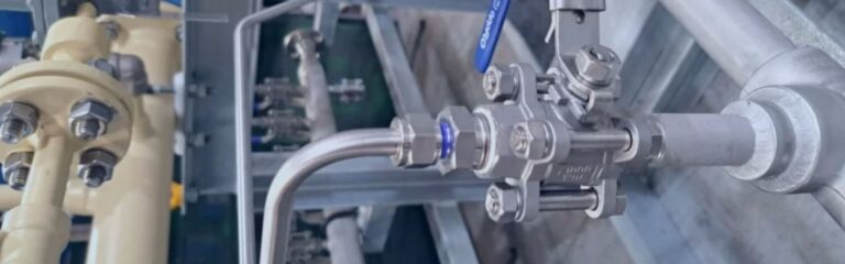
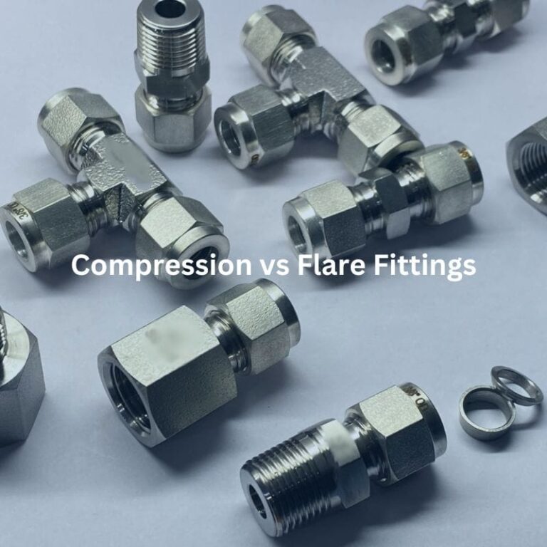
In the domain of fluid power and instrumentation, the selection of tube fittings is a critical engineering decision that dictates system integrity, leak-tight performance, and safety. While numerous specialized connectors exist, the industry fundamentally relies on two primary mechanical architectures: Compression (Bite-Type) Fittings and Flare Fittings.
Compression fittings, often referred to as “bite-type” fittings, are the standard for instrumentation and high-pressure process lines. Their primary advantage is that they require no specialized tube preparation beyond a square cut and deburring.
The mechanics of compression fittings rely on the axial movement of a nut to drive a ferrule (or ferrules) into a fitting body, creating a seal.

For a compression fitting to hold pressure, the ferrule must be harder than the tubing. As the nut is tightened, the ferrule undergoes elastic and then plastic deformation. The leading edge of the ferrule “bites” into the tube surface, displacing a small amount of material. This creates a mechanical interlock that can withstand pressures exceeding the burst pressure of the tubing itself.
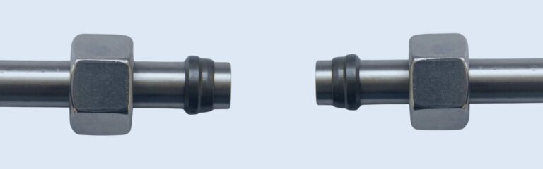
Flare fittings rely on the deformation of the tube end itself to create a seal. Unlike compression fittings, the tube must be “flared” using a specialized tool before assembly.
The Joint Industry Council (JIC) 37° flare is the most ubiquitous fitting in hydraulic systems. The seal is created by the metal-to-metal contact between the 37° flared end of the tube and the 37° nose of the fitting.
Commonly used in automotive, refrigeration, and low-pressure brass applications. The 45° angle provides a larger sealing surface area, which is beneficial for softer materials like copper or aluminum tubing, though it cannot reach the pressure ratings of the 37° JIC stainless steel equivalent.
The following table provides a quantitative and qualitative comparison to assist in the selection process during the design phase.
| Feature | Double-Ferrule Compression | JIC 37° Flare |
| Primary Seal Method | Plastic deformation of ferrule | Mating of flared tube surface |
| Tube Preparation | Square cut and deburr only | Square cut, deburr, and mechanical flare |
| Pressure Rating | Up to 15,000 PSI (dependent on wall) | Up to 7,500 PSI (size dependent) |
| Vibration Resistance | Excellent (Double ferrule colleting) | Good (Sleeve protects flare) |
| Gas-Tight Sealing | Superior (Standard for Helium/Hydrogen) | Moderate (Better for liquids) |
| Reusability | Limited (Ferrules are permanently set) | High (Tube can be re-flared if needed) |
| Governing Standards | ASME B31.3, ASTM F1387 | SAE J514, ISO 8434-2 |
| Common Materials | 316 SS, Monel, Hastelloy, PFA | Carbon Steel, Brass, 316 SS |
The longevity of a tube fitting is dictated by the interaction between the fitting material, the fluid medium, and the external environment.
The industry standard for process control. The “L” denotes low carbon content (<0.03%), which prevents intergranular corrosion during welding. The addition of 2-3% Molybdenum provides resistance to chlorides, making it essential for marine and offshore applications.
Composed of roughly 67% Nickel and 23% Copper. This material is specifically utilized in systems transporting hydrofluoric acid or in seawater environments where stainless steel may suffer from Pitting and Crevice Corrosion.

Predominant in hydraulic machinery. Modern standards require Zinc-Nickel (Zn-Ni) plating over traditional Hexavalent Chromium to provide >720 hours of salt spray resistance (ASTM B117), preventing red rust.
| Material | -20°F to 100°F | 200°F | 400°F | 600°F | 800°F | 1000°F |
| 316 Stainless | 1.00 | 1.00 | 0.93 | 0.82 | 0.76 | 0.69 |
| Carbon Steel | 1.00 | 0.95 | 0.88 | 0.79 | – | – |
| Brass | 1.00 | 0.85 | 0.50 | – | – | – |
| Alloy 400 | 1.00 | 0.87 | 0.79 | 0.79 | 0.75 | – |
Engineers must ensure the tube’s wall thickness is compatible with the fitting’s “bite” capability and the system’s working pressure.
| Tube OD | 0.028″ Wall | 0.035″ Wall | 0.049″ Wall | 0.065″ Wall | 0.083″ Wall | 0.095″ Wall |
| 1/4″ | 4,000 | 5,100 | 7,500 | 10,200 | – | – |
| 3/8″ | 2,600 | 3,300 | 4,800 | 6,500 | – | – |
| 1/2″ | – | 2,600 | 3,700 | 5,100 | 6,700 | – |
| 3/4″ | – | – | 2,400 | 3,300 | 4,200 | 4,900 |
| 1″ | – | – | – | 2,400 | 3,100 | 3,600 |
CRITICAL SAFETY NOTE: Never use “Thin Wall” tubing for high-pressure gas services as the ferrule may not achieve sufficient bite depth to prevent tube blowout.
Failure in tube fitting systems is rarely due to manufacturing defects; 90% of failures are attributed to improper installation.
The selection between compression and flare fittings hinges on a balance of pressure requirements, installation time, and the necessity for reusability. For high-integrity instrumentation where gas-tight sealing is paramount, the double-ferrule compression fitting remains the engineered choice. For rugged hydraulic systems subjected to mechanical shock and frequent maintenance, the 37° JIC flare fitting provides a reliable, metal-to-metal solution. Adherence to ASTM, SAE, and ASME standards during the installation and maintenance phases is non-negotiable for the preservation of industrial safety and operational efficiency.
The two main types of tube fittings are compression fittings and flare fittings.
Compression tube fittings use a ferrule that compresses around the tube to create a tight seal when tightened.
Flare tube fittings are used for high-pressure applications, where the tube’s end is flared and connected to the fitting to create a secure seal.
Yes, compression fittings are generally easier and quicker to install because they do not require flaring the tube before installation.
Flare fittings are often preferred for high-pressure applications because the flared end creates a stronger, more durable seal.
Compression fittings can be reused if they are not damaged, but the ferrule should be checked for wear to ensure a proper seal.
Find out more about Topa Blog and learn more about specialized hydraulic fittings.


