Ferrule cracking after hose crimping can come from insufficient material ductility, local wall geometry, surface or seam defects, stress concentration, uneven die loading, excessive deformation, or an incompatible hose-and-fitting condition. A crack’s appearance can direct the investigation, but it cannot confirm one root cause by itself. Stop work, isolate the assembly, document it before handling, and do not install, re-crimp, weld, grind, or reuse a cracked ferrule. The reliable approach is a fracture investigation that separates observations from possible contributors and preserves the evidence needed to test each branch.
Triage the Crack Before Evidence Is Lost
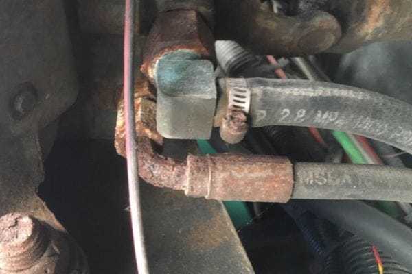
A cracked ferrule is a nonconforming safety-related condition, not a cosmetic issue to be worked around. The immediate goal is to prevent use and preserve the original state before cleaning, cutting, or repeated handling changes the fracture evidence.
Stop the crimp process and segregate the affected assembly, related components, and any other parts made under the same traceable conditions. Mark the item without writing across the crack. Record part numbers, lots, hose identity, fitting and ferrule series, machine, die set, crimp program or specification revision, operator record, date, and sequence position.
Preserve the original condition
Photograph the full assembly and then the crack at increasing magnification. Include orientation references showing the ferrule front, rear, die split locations, and fitting body. Record whether the crack was visible before crimping, appeared under load, appeared immediately after release, or was found later during inspection.
Do not force the crack open, remove plating, polish the surface, or section the only sample before an investigation plan is agreed. Those actions can destroy the origin, smear fracture features, or make a coating crack look like base-metal fracture. Preserve uncracked comparison parts from the same lot when available.
Classify Location, Direction, and Discovery Time
Classification converts “the ferrule cracked” into observations that can be compared with specific failure branches. It should describe what is visible without naming a cause prematurely.
Location and direction
Record whether the indication is at the rear entry, rear compression transition, main sleeve body, die-contact boundary, front transition, attachment region, or another controlled feature. Then describe direction: longitudinal along the ferrule axis, circumferential around it, diagonal, branched, or irregular.
Also record length qualitatively, whether the indication reaches an edge, whether it is open, and whether deformation surrounds it. Avoid calling it a hairline defect as if small width made it acceptable. Width can change after unloading and does not establish depth or material involvement.
When it appeared
A mark documented before crimping creates a different investigation path from a fracture first visible after closure. An indication that opens during crimping may have begun as a pre-existing discontinuity that propagated under deformation, or it may have initiated during the process. Discovery time alone does not decide between them.
If several sequential parts are available, record their order and condition without continuing production merely to create more failures. A single cracked sample is sufficient to stop and investigate; it is not evidence that every other part is good or that the event was random.
Material and Ductility Branch
The ferrule material must tolerate the plastic deformation required by its approved crimp design. If actual material condition does not match design intent, cracking can initiate where strain or stress is locally highest.
Possible material contributors
Possible contributors include unsuitable material identity, inconsistent heat-treatment condition, reduced ductility, local hard zones, inclusions, seams, laps, or other metallurgical discontinuities. Surface processing can also affect the local condition. These terms are hypotheses until supported by traceable material and laboratory evidence.
Do not infer material grade from color, spark appearance, magnet response, or one hardness impression. Likewise, a certificate linked only to a general order does not necessarily prove the tested sample came from the cracked ferrule. Traceability must connect the evidence to the actual lot and part.

Evidence for confirmation
Useful evidence can include controlled material records, positive material identification where appropriate, hardness mapping under a qualified plan, metallographic examination, fracture-surface analysis, and comparison with uncracked parts. Test selection should be made by competent engineering or laboratory personnel so sample preparation does not erase the feature being studied.
No universal hardness, elongation, or ductility value can be supplied for all ferrules. Compare results with the controlled drawing, material specification, process requirements, and validated design for that exact part.
Wall Geometry and Stress-Concentration Branch
Even suitable material can crack when local geometry concentrates deformation. Wall thickness, transitions, grooves, attachment features, and machining marks influence how the ferrule responds as the dies drive it inward.
Local section changes
A thin region may undergo a different strain path from an adjacent heavy section. An abrupt step or small transition radius can focus stress where the sleeve changes stiffness. Grooves or retention features may also change the effective cross-section. These features are not automatically defects, but they need to match controlled design intent.
Measure relevant geometry from defined datums using an appropriate method. An outside diameter alone cannot reveal eccentric wall thickness or an off-center bore. Compare multiple circumferential locations and uncracked samples rather than relying on one section through a favorable plane.
Machining and surface features
Tool marks, scratches, dents, burrs, seam-like indications, or damaged edges may act as local initiation sites. Their importance depends on orientation, depth, location, surrounding geometry, and the crimp deformation path. A mark parallel to expected deformation can behave differently from one crossing a highly strained transition.
Do not grind away the feature to see whether it disappears. Preserve it, photograph it, and use a planned examination that can distinguish a shallow surface condition from a deeper base-metal discontinuity.
Process Loading and Assembly-Compatibility Branch
Crimping can create cracking when the sleeve experiences more deformation or less uniform support than the design allows. Process evidence must separate machine commands from what the ferrule actually experienced.
Over-compression and uneven loading
Possible contributors include incorrect die identity, wrong machine setting, calibration error, improper axial position, debris at die contact, damaged tooling, or eccentric setup. Uneven segment contact may create localized high deformation, while an incorrect closure can exceed the approved ferrule path.
Final diameter is relevant but incomplete. Record location, orientation, roundness, instrument, timing, and calibration. Review die marks and compare machine records with the exact approved specification. Never compensate for a dimensional discrepancy by re-crimping the cracked sleeve.
Incompatible component stack
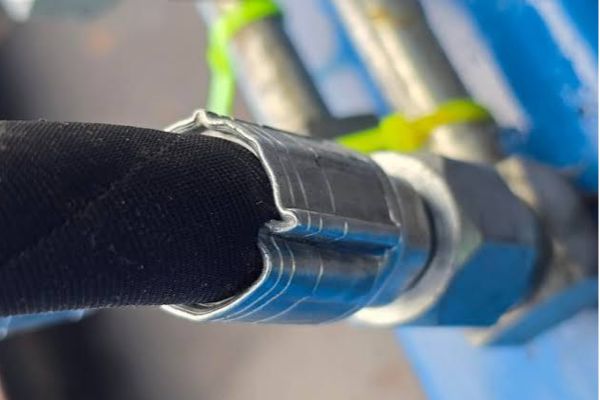
The wrong hose construction, fitting series, ferrule, stem, or preparation method can change support inside the sleeve. Excess material, insufficient internal support, incomplete insertion, or an unintended skive condition may alter how the ferrule closes. The same dash size does not prove compatibility.
Confirm hose manufacturer, series, ID, construction, fitting and ferrule identity, assembly preparation, insertion, machine, die, and current crimp data. A process may be correctly repeated yet still be wrong for the selected component combination.
Pre-Existing Defect or Crimp-Created Crack?
The investigation must distinguish a discontinuity that existed before crimping from one initiated by the crimp, while recognizing that a pre-existing flaw can grow during closure. These categories can overlap in the final fracture.
Review incoming inspection records and any pre-crimp photographs, but do not treat absence from a routine visual check as proof the defect did not exist. A subsurface discontinuity or closed surface seam may become visible only after deformation. Conversely, an initially sound surface may crack because of local strain, geometry, or process loading.
Test both origin paths
Coating indications require special care. Plating can crack or craze without the base metal being fractured, and base-metal cracks can also break the coating above them. Visual color or magnification alone may not separate the layers. A controlled cross-section or laboratory examination can determine depth, but destructive work should follow an evidence-preservation plan.
Lot comparison can strengthen the analysis. Examine uncrimped ferrules, normally crimped samples, and the failed item with traceable links. The goal is not to find a convenient difference; it is to test whether a proposed cause consistently explains origin, direction, location, and process history.
Fracture Location Guides but Does Not Prove Cause
Different crack locations expose different parts of the fault tree. They prioritize evidence collection, but similar-looking cracks can arise from different combinations of material, geometry, and load.
| Crack observation | Possible contributors | Evidence needed next |
| Crack at rear or front transition edge | Abrupt section change, edge defect, die-position error, local over-deformation | Controlled dimensions, die-contact map, axial position, surface and fracture examination |
| Longitudinal body crack | Material or seam discontinuity, eccentric wall, localized die loading | Wall map, lot traceability, fracture origin, tooling and roundness records |
| Circumferential indication | Local transition strain, machining feature, process-position issue | Drawing comparison, indication depth, section geometry, machine and die records |
| Coating-only network | Plating response, surface preparation, base-metal deformation beneath | Layer-depth examination and comparison with uncrimped controls |
| Crack aligned with a die boundary | Uneven segment contact, setup, tooling damage, or coincidental geometry feature | Die inspection, contact marks, machine calibration, repeated orientation evidence |
Use morphology to prioritize evidence
A transition-edge crack deserves a different first review from a longitudinal body crack because the former immediately raises questions about section change and axial crimp position. The latter makes wall continuity, seams, eccentricity, and circumferential loading higher-priority branches. Neither location confirms the answer.
Build a Root-Cause Evidence Package
A defensible conclusion links the fracture origin to a mechanism, shows why competing explanations are weaker, and remains traceable to the affected part and process. A list of possible causes is only the start.
Preserve the cracked item, uncrimped lot samples, nearby production samples, hose remnants, tooling condition, and machine records. Assemble controlled drawings, material and process specifications, receiving data, crimp instructions, calibration status, measurement records, photographs, and sample chain of custody.
Link each hypothesis to traceable proof
Define each hypothesis in testable language. For example, “uneven die loading initiated the fracture at a segment boundary” requires consistent orientation, contact evidence, tooling findings, and a fracture origin at the relevant location. “Low ductility caused the crack” requires material evidence connected to the part, not just a brittle-looking surface.
Check whether the proposed mechanism also explains the absence of cracking in comparison samples. Differences in lots, wall geometry, setup, or crimp sequence may narrow the branch, but correlation should not be presented as causation until the fracture origin and supporting records agree. Record negative findings because they prevent a later review from reopening branches already tested with suitable evidence.
Document confirmed facts, ruled-out branches, unresolved questions, containment scope, and the authority approving disposition. Do not release related assemblies merely because only one cracked sample was observed. The disposition must be based on the defined risk, evidence, and applicable quality system.
Conclusion
Ferrule cracking is best investigated as a branching fracture problem, not attributed to a single visible feature. First isolate the assembly and preserve its original condition. Then classify location, direction, and discovery time before examining material condition, wall geometry, surface features, die loading, axial position, and complete component compatibility. A transition-edge crack and a longitudinal body crack justify different first measurements, yet neither proves root cause. Coating cracks must also be separated from base-metal fracture through controlled evidence. For ferrule cracking after hose crimping, retain the failed and comparison parts, traceable lot records, drawings, crimp and calibration data, photographs, measurements, and qualified fracture-analysis results before deciding containment or corrective action.
FAQ
Is a hairline ferrule crack acceptable if it does not open?
No, a suspected crack must be treated as a nonconformity and investigated. Apparent width does not establish depth, material involvement, or safety.
How can plating cracks be distinguished from base-metal cracks?
Visual inspection alone may not distinguish them. A controlled layer-depth or cross-sectional examination should be planned without destroying the only fracture-origin evidence.
Can a cracked ferrule be re-crimped to close the crack?
No, re-crimping cannot restore verified material integrity and may worsen the fracture. Do not weld, grind, repair, install, or reuse the assembly.
Does one cracked sample prove the entire lot is defective?
No, but one sample is enough to stop and define containment. Lot disposition requires traceability, comparison evidence, process history, and a risk-based investigation.
What evidence should be preserved first?
Preserve the assembly, crack photographs, orientation, part and lot identities, hose and fitting data, die and machine records, crimp specification, measurements, and unmodified comparison samples.