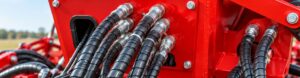
A one-piece hydraulic hose fitting can pull off when the hose, fitting, insertion, crimp, or assembly process is wrong. Preventing that failure requires all five checks below—not simply a tighter crimp. For a hose assembly shop, this approach reduces rework and helps keep an incorrectly built assembly from reaching a machine.
Why One-Piece Fittings Still Pull Off
The one-piece design removes one mismatch, not every mismatch
A one-piece fitting has a fitting body or stem and a ferrule preassembled or fixed as one assembly component; the exact construction varies by product series. This arrangement prevents an operator from selecting a separate, incorrect ferrule, which is a useful error reduction. It does not automatically make the fitting compatible with every hose of the same nominal size, create the correct crimp, or guarantee retention under pressure impulses and mechanical loading.
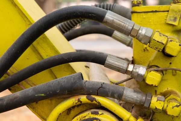
Pull-off is usually a system failure
Retention comes from a controlled relationship among the fitting stem profile, ferrule deformation, hose reinforcement, insertion depth, and finished crimp diameter. If any one of those relationships falls outside the qualified assembly specification, the fitting may move, leak, or separate. The five checks are therefore connected: passing four does not compensate for failing the fifth.
Before examining an assembly, shut down the equipment, release hydraulic pressure and stored energy, and follow the equipment and component manufacturers’ safety procedures. Never search for a pinhole leak with a hand, and never loosen a connection to “see whether pressure remains.” Fluid injection injuries and uncontrolled hose movement require immediate, serious treatment.
Check 1: Match the Hose Construction to the Fitting Series
Size alone cannot establish compatibility
The first check is whether the exact one-piece fitting series is approved for the specific hose manufacturer, hose series, size, and construction. Two hoses marked with the same dash size may differ in tube material, reinforcement type, reinforcement position, cover thickness, and outside diameter. Those differences affect how the stem enters the bore, how the ferrule compresses the hose, and whether the reinforcement is captured as intended.
Use current, traceable manufacturer crimp data rather than a visual comparison with an old assembly. A stem that appears to fit can still damage the tube, push reinforcement aside, or fail to develop retention. If the hose and fitting come from different product systems, do not assume cross-brand compatibility from dimensions or catalog language; obtain documented approval or use a validated combination.
Confirm the complete hose-and-fitting identity
Record the following before cutting or crimping:
- Hose manufacturer, full series designation, nominal ID or dash size, and relevant lot or date code when required by the shop’s traceability procedure.
- One-piece fitting manufacturer, complete part number, fitting series, end connection, material, and orientation.
- Approved skive or no-skive preparation, die set, crimp target and tolerance, and any specified measurement location.
- Application limits, including working pressure, temperature, fluid, impulse duty, bend behavior, and environmental exposure.
The working capability of the finished hydraulic hose assembly is governed by its lowest-rated component and by application conditions. A fitting’s catalog rating by itself does not qualify the complete assembly. When the combination is absent from the current crimp data, stop and resolve the gap rather than substituting a “close” series.
Check 2: Control Hose Preparation and Full Insertion
A correct crimp cannot recover missing insertion depth
The hose must reach the position defined by the assembly instructions before crimping. If it stops short, the ferrule may compress cover or reinforcement in the wrong zone, leaving too little effective engagement with the stem. Causes include an angled cut, debris in the bore, a damaged stem, incorrect skiving, insufficient lubrication where an approved lubricant is specified, or simple loss of the insertion mark during handling.
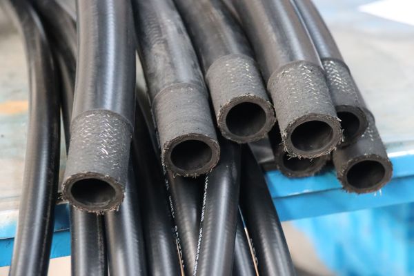
Cut the hose square with suitable equipment, inspect the bore, and clean it according to the required cleanliness process. Follow the exact preparation instruction for skiving, cover removal, cleaning, and approved lubricant; these details are series-specific. Over-skiving can remove material needed for support, while under-skiving can prevent insertion or change how the ferrule loads the reinforcement.
Mark insertion before the assembly enters the crimper
Use the manufacturer’s specified insertion depth or insertion reference and place a visible mark at the ferrule edge. After inserting the hose fully, verify the mark has not shifted before crimping and check it again afterward. Some product designs provide an inspection hole or other feature, but use it only as the manufacturer directs; it does not replace the specified depth check.
A practical insertion control should answer four questions:
- Was the hose cut and prepared by the specified method?
- Was the required insertion reference measured with a suitable tool rather than estimated?
- Did the hose remain at full insertion while the assembly was positioned in the dies?
- Does the post-crimp mark or inspection feature show any movement?
If the insertion mark moves, do not recrimp and release the assembly without an approved disposition. Determine whether the hose backed out, the fitting was mispositioned in the dies, or the preparation prevented full engagement. Rework rules must come from the applicable hose-and-fitting manufacturer because additional crimping can further damage reinforcement or distort the stem.
Check 3: Apply the Exact Crimp Specification
Crimp diameter is product-specific
The correct finished diameter, tolerance, die selection, and measurement location come from current data for the exact hose-and-fitting combination. There is no universal crimp diameter for a dash size, and “slightly smaller for more grip” is unsafe reasoning. Excessive crimp can damage reinforcement, restrict the tube, or deform the stem; insufficient crimp can leave inadequate ferrule engagement and allow pull-off or leakage.
Retrieve the approved specification at the workstation and confirm that the crimper, die set, and settings correspond to it. Crimp data can change with hose series, fitting family, size, production design, or tooling. A handwritten value copied without its source, revision, product scope, and measurement convention is not enough to release an assembly.
Measure the finished crimp correctly
Measure only after the assembly and measuring tool are in the condition required by the procedure. Use a calibrated instrument with suitable contact surfaces, take measurements at the specified location, and avoid distorted areas such as die impressions or part markings unless the instructions state otherwise. If the procedure calls for readings around the circumference, record them; a single favorable reading can hide taper or an uneven crimp.
| Verification point | What must match | Pull-off risk if wrong |
|---|---|---|
| Crimp target | Current value and tolerance for the exact combination | Too little retention or component damage |
| Die and tooling | Specified die set, machine setup, and condition | Taper, under-crimp, over-crimp, or uneven compression |
| Measurement method | Required location, orientation, tool, and timing | A false pass despite an out-of-spec crimp |
| Stem condition | No prohibited collapse, distortion, or internal damage | Restricted flow, damaged tube, or reduced joint integrity |
When a finished diameter is outside tolerance, quarantine the assembly and follow the documented nonconformance process. Do not average an out-of-limit reading into acceptance or change the target to match what the machine produced.
Check 4: Verify the Crimper, Tooling, and Process
Good parts can fail in an uncontrolled process
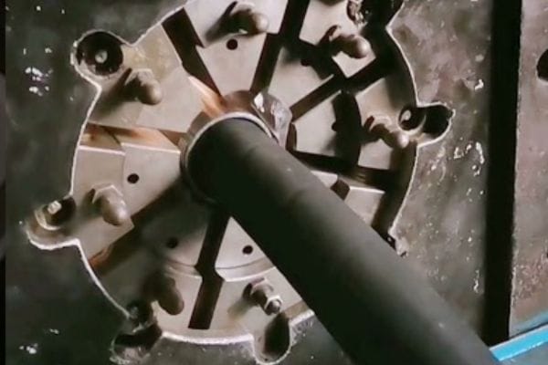
A correct hose and fitting can still produce a weak joint when the crimper is miscalibrated, the wrong dies are installed, tooling is worn or contaminated, or the fitting sits incorrectly in the die cage. Machine display values do not by themselves prove the resulting diameter. Verification must connect the selected program and tooling to a physical measurement of the finished crimp.
Establish a pre-use check covering machine status, calibration or verification status, die identity, die cleanliness, visible wear, and the correct setup for the fitting shape. Elbows and long-drop fittings may need particular positioning to prevent interference or side loading. Operators should also confirm that the ferrule is located at the intended crimp position rather than centered by appearance.
Lock the specification to the job traveler
The build record should carry enough information for another qualified person to reproduce and inspect the assembly. At minimum, connect the hose part number, fitting part number, preparation method, insertion control, crimp specification revision, machine, dies, measured results, and operator or station identity. Barcode scanning or controlled digital recipes can reduce transcription mistakes, but only when part labels and master data are accurate.
Use these process gates before releasing production:
- Verify the first completed assembly against the job specification before continuing the batch.
- Repeat checks at the frequency required by the quality plan and after a die, machine, setup, or material change.
- Segregate suspect output back to the last accepted verification point if a process check fails.
- Preserve records that link measured results to the parts and specification used.
These controls are especially valuable during urgent repairs, when speed creates pressure to rely on memory. A short pause to verify a recipe is faster than disassembling a machine again after leakage or pull-off.
Check 5: Inspect, Test, and Release the Finished Assembly
Inspection must look beyond the crimp number
A diameter within tolerance is necessary, but it is not the entire release decision. Inspect the insertion mark, ferrule position, crimp length and uniformity as applicable, exposed reinforcement, cracks, die damage, stem-bore distortion, hose twist, fitting orientation, cleanliness, and end-connection condition. Confirm that routing will not impose tension, excessive bend, abrasion, or side load near the fitting after installation.
Thread form and sealing method also deserve separate verification. JIC, SAE 45-degree flare, NPT/NPTF, BSPP/BSPT, ORFS, ORB, metric, DIN, and JIS connections are not interchangeable merely because they appear to mate. Measure diameter and pitch or TPI, distinguish straight from tapered threads, and identify the seat, sealing face, or O-ring arrangement; thread sealant cannot repair a mismatched thread or damaged sealing surface.
Testing follows the applicable procedure
Perform proof, pressure, cleanliness, electrical-continuity, or other testing only when required and according to the applicable manufacturer, customer, equipment, or quality procedure. Use guarded equipment and keep personnel away from a pressurized assembly. A shop-made pull test or arbitrary pressure test is not a substitute for a qualified hose-and-fitting system or for the specified production inspection.
Release the assembly only when its identification and records agree with the physical build. Cap or protect cleaned ends as required, prevent contamination during storage, and label the assembly so that a future replacement can be traced without guessing.
What to Do When Pull-Off or Hose Movement Is Found
Quarantine first, investigate by evidence
If a fitting has moved, leaked at the hose-to-fitting interface, or separated, stop the equipment, isolate energy, and quarantine the assembly and related production. Do not push the hose back into the ferrule, tighten an unrelated threaded connection, or add sealant. Preserve the hose, both fittings, labels, build record, machine data, dies used, and operating information so the failure can be assessed without destroying its clues.
The investigation should compare physical evidence with the five controls rather than jump to a single cause. Check whether the correct hose and fitting were used, whether insertion evidence remains, whether crimp measurements and tooling records are credible, whether the assembly shows twist or external loading, and whether operating pressure, impulse, temperature, fluid, and routing were within the qualified limits. Similar assemblies made since the last verified process check may also need controlled segregation and review.
Information needed for a reliable technical review
Prepare a concise evidence package:
- Hose manufacturer, series, size, markings, and available traceability details.
- Complete fitting part number, series, material, orientation, and clear photos of the whole fitting, ferrule, crimp, thread, and sealing face.
- Insertion requirement and evidence, crimp target and tolerance, actual readings, measurement location, dies, machine, and source revision for the crimp data.
- Working pressure, pressure spikes if known, temperature, fluid, equipment function, routing, bend radius condition, abrasion, movement, and time in service.
- Failure position and condition, including whether the hose slipped, reinforcement pulled out, ferrule cracked, stem deformed, or leakage appeared before separation.
This record supports a technical decision without assuming that every separation is caused by under-crimping. It also makes the next replacement faster: the shop can retrieve verified details instead of identifying a damaged part from one photograph. Where recurring failures involve routing, vibration, or abrasion, consult the equipment and hose manufacturers before changing fitting orientation, hose length, clamps, or protective measures.
A Practical Release Rule for One-Piece Fitting Pull-Off Prevention
Five passes are required
Release a one-piece hydraulic hose fitting assembly only after the hose/fitting match, preparation and insertion, crimp specification, controlled tooling process, and final inspection all pass against traceable requirements. One-piece construction reduces the chance of choosing a separate ferrule incorrectly, but it cannot compensate for an unapproved hose, shallow insertion, an incorrect crimp, uncontrolled tooling, or damaging installation conditions.
Before the next build or technical inquiry, prepare the exact hose and fitting part numbers, current manufacturer crimp data, insertion requirement, machine and die information, measured crimp results, application conditions, and clear component photos. Correct matching is more important than visual similarity, speed, or the lowest component price because the finished assembly must work as one qualified system.
Frequently Asked Questions
Can a one-piece fitting be recrimped if the hose moves after crimping?
Do not recrimp it unless the hose-and-fitting manufacturer provides an approved rework instruction for that exact condition. Quarantine the assembly, document the movement and measurements, and determine why insertion or retention failed.
Does the same dash size mean a different hose brand will fit?
No; dash size identifies nominal size, not complete hose construction or approved fitting compatibility. Confirm the exact hose series, fitting series, and current crimp data before assembly.
Can a smaller crimp diameter prevent pull-off?
Only the specified crimp target and tolerance may be used. Crimping smaller than specified can damage reinforcement, the tube, or the fitting stem without creating a safe joint.
Is pressure testing enough to prove fitting retention?
No; a production pressure test, when required, evaluates the assembly under the defined test conditions but does not excuse incorrect components or process results. Compatibility, insertion, crimp measurements, tooling control, and final inspection still need independent verification.
Should a separated assembly be cut apart immediately?
No; first isolate it, preserve its as-found condition, photograph it, and collect the build and application records. Cutting can destroy evidence needed to distinguish shallow insertion, incorrect crimping, incompatible components, or external loading.