
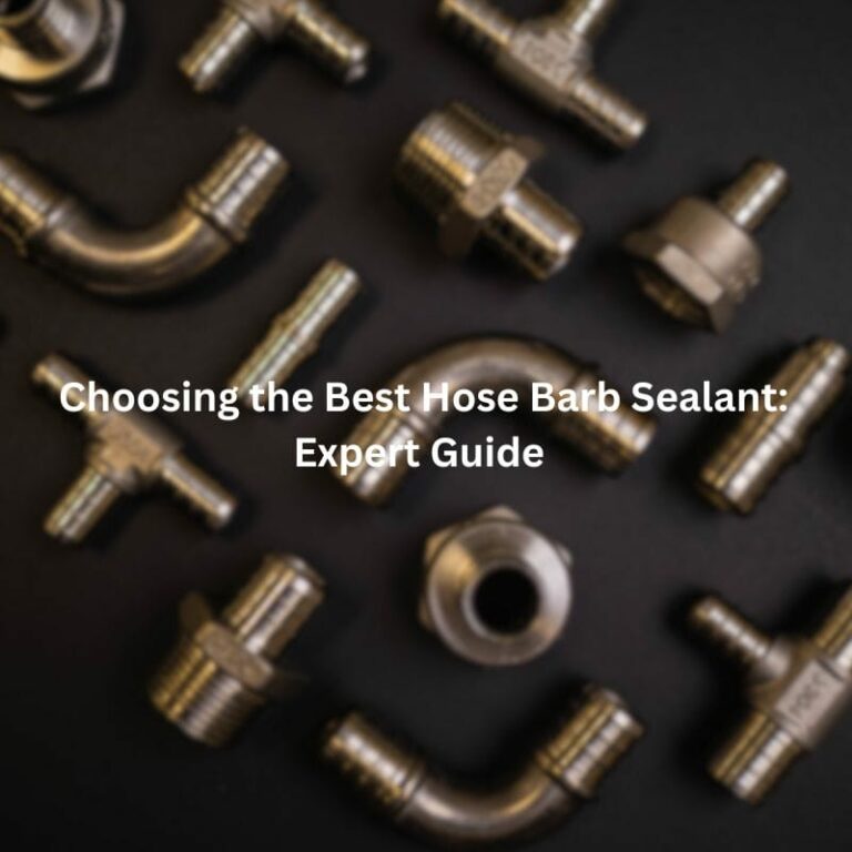
Choosing the Best Hose Barb Sealant: Expert Guide
Introduction
In the realm of fluid handling and mechanical assemblies, the role of sealants in hose barb fittings is paramount. These fittings, designed to securely connect hoses to various components, rely heavily on effective sealing to prevent leaks and ensure operational integrity. Sealants serve a crucial function in enhancing the sealing capabilities of hose barb fittings, particularly in applications where reliability and durability are critical. They help to bridge gaps, fill irregularities, and create a tight seal between mating surfaces, thereby preventing leakage of liquids or gases under pressure.
Understanding Hose Barb Connections
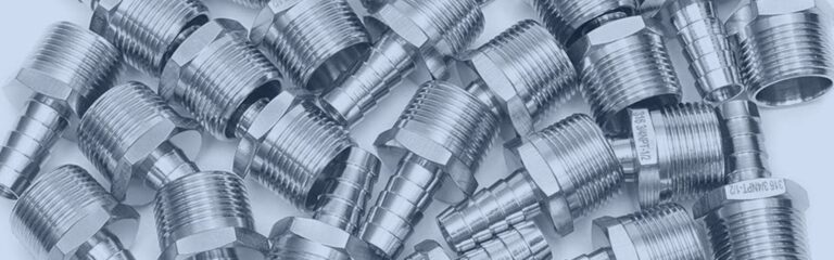
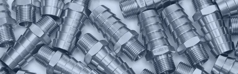
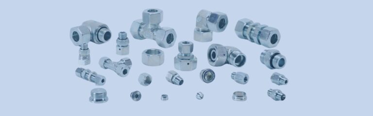
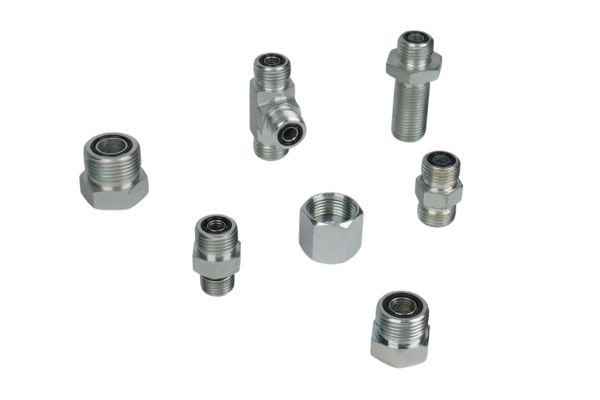
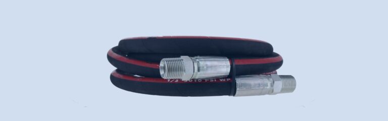
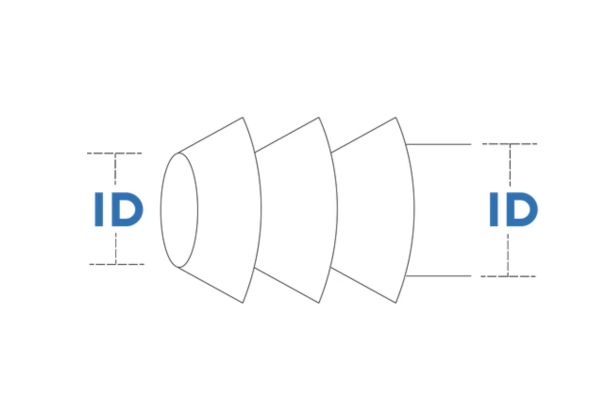
Hose barb fittings are integral components in fluid handling systems, designed with barbed ends that grip hoses securely. Their primary function is to create a reliable connection between hoses and other components without the need for additional tools or clamps.
The barbed ends feature ridges or serrations that provide a tight seal when inserted into the inner diameter of a hose, ensuring a secure fit that prevents leakage under pressure. This design also allows for flexibility in hose selection, accommodating various sizes and materials.

Common Applications in Various Industries
Hose barb fittings find widespread use across diverse industries due to their versatility and efficiency in fluid transfer applications. Some common industries and applications include:
Automotive: Used in coolant systems, fuel lines, and pneumatic systems.
Medical: Vital for connecting tubing in medical devices and equipment.
Agriculture: Employed in irrigation systems and pesticide delivery.
Industrial Manufacturing: Utilized in hydraulic systems, air compressors, and chemical processing.
Home and Garden: Found in water and gas plumbing connections, as well as in aquarium and pond setups.
Types of Hose Barb Sealants
Liquid Sealants
Characteristics and Application Methods:
Liquid sealants are highly versatile solutions applied directly onto hose barb fittings or threaded connections to establish a secure seal. Available in liquid or paste forms, they offer the following key characteristics:
Versatility: Suitable for a wide range of materials including metals, plastics, and elastomers, accommodating diverse application needs.
Ease of Application: Applied directly from a container or with a brush, allowing for precise and flexible coverage over mating surfaces.
Curing Time: Require sufficient drying or curing time to achieve optimal sealing effectiveness, ensuring a reliable bond.
Pros and Cons Compared to Other Types:
Pros: Provide a reliable seal without the need for mechanical compression, adapting well to irregular surfaces and complex geometries. They can be removed and reapplied if necessary, offering flexibility during assembly.
Cons: Vulnerable to degradation over time, especially in harsh environments with extreme temperatures or exposure to aggressive chemicals. Periodic re-application may be necessary after disassembly.
Thread Seal Tapes

How They Work with Hose Barb Fittings:
Thread seal tapes, also known as plumber’s tape or PTFE tape, are thin, flexible tapes wrapped around the male threads of hose barb fittings before assembly. Their primary function is to fill gaps and create a tight seal when threaded connections are tightened together.
Best Practices for Application:
Clean Threads: Ensure threads are thoroughly cleaned and free of dirt, debris, and old tape residue before applying new tape.
Correct Wrapping: Wrap the tape tightly around the male threads in the direction of assembly to prevent unraveling during installation.
Avoid Overlapping: Do not overlap the tape excessively as it may interfere with proper engagement of the threads and lead to leaks.
Anaerobic Sealants
Advantages of Sealing Threaded Connections:
Anaerobic sealants are formulated to cure in the absence of air (anaerobic conditions) when applied between closely fitted metal surfaces. They offer several key advantages:
High Strength: Provide strong, durable bonds that enhance joint integrity, particularly in applications prone to vibration and mechanical stress.
Chemical Resistance: Resist a wide range of chemicals and fluids, ensuring long-term sealing performance in demanding environments.
Temperature Resistance: Maintain effective sealing properties across a broad range of temperatures, from extreme cold to high heat.
Suitable Applications and Considerations:
Automotive and Industrial: Ideal for sealing hydraulic fittings, pipe threads, and other metal-to-metal connections where reliable, long-lasting seals are critical.
Assembly Requirements: Require clean, dry surfaces and metal-to-metal contact for proper curing. Ensure surfaces are free of oil, grease, and contaminants before application to maximize adhesion and sealing effectiveness.
Each type of hose barb sealant offers distinct advantages tailored to specific application requirements and environmental conditions. Choosing the right sealant involves careful consideration of material compatibility, durability needs, and ease of application to ensure optimal performance in fluid handling systems.
Factors to Consider When Choosing
Compatibility
Matching Sealant Type with Materials:
Selecting the right sealant involves ensuring compatibility with the materials of the hose barb fittings and the hoses themselves. Different sealants are formulated to adhere to specific materials, such as metals, plastics, and elastomers. For example, some sealants work well with brass and stainless steel fittings, while others are designed for plastic or rubber components. Using an incompatible sealant can lead to poor adhesion and potential leakage.
Impact on Seal Integrity Over Time:
The long-term performance of the sealant is crucial for maintaining the integrity of the hose barb connection. Factors such as material expansion, contraction, and potential chemical reactions must be considered. Sealants that degrade or lose effectiveness over time can compromise the seal, leading to leaks and system failures. It’s important to choose a sealant with proven durability for the specific application.
Environmental Conditions
Temperature:
The operational temperature range of the system is a key factor in sealant selection. Some sealants perform well in extreme cold or heat, while others may lose their sealing properties under such conditions. Ensuring the sealant can withstand the expected temperature range is essential for maintaining a reliable seal.
Pressure:
The pressure within the system also influences the choice of sealant. High-pressure applications require sealants that can maintain their integrity under stress. Sealants that are not designed for high-pressure environments may fail, leading to leaks and potential system damage.
Chemical Exposure:
The chemical compatibility of the sealant with the fluids or gases passing through the system is another critical consideration. Sealants exposed to harsh chemicals, solvents, or fuels must resist degradation and maintain their sealing properties. Using a sealant that reacts negatively with the system’s contents can result in seal failure and contamination.
Ease of Application
User-Friendly Application Methods:
The ease of applying the sealant can significantly impact the efficiency and reliability of the sealing process. Sealants that are simple to apply, such as those that come in convenient dispensers or brush-on formats, help ensure consistent coverage and reduce the risk of application errors.
Drying or Curing Times:
The required drying or curing time for the sealant to achieve full effectiveness should align with the assembly process and operational needs. Quick-drying sealants are beneficial for applications that require immediate use, while those with longer curing times may offer stronger bonds but necessitate longer wait times before the system can be pressurized or put into service. Balancing the need for rapid turnaround with the desired sealing strength is essential for choosing the appropriate sealant.
Step-by-Step Guide for Applying Different Sealant Types
Liquid Sealants
Preparation:
Begin by thoroughly cleaning the surfaces to be sealed. Remove any dirt, oil, or remnants of old sealant using a solvent or degreaser.
Application:
Use a brush or applicator to apply the liquid sealant directly onto the threads or mating surfaces of the hose barb fitting.
Apply a uniform coat, ensuring complete coverage without excess. Avoid applying too much sealant, as it can squeeze out and compromise the seal.
Curing:
Allow the sealant to dry or cure completely as per the manufacturer’s instructions. This ensures proper bonding and sealing effectiveness.
Wait until the recommended curing time has passed before pressurizing the system or exposing it to fluids to prevent premature failure.
Thread Seal Tapes
Preparation:
Start with clean, dry threads on the male end of the hose barb fitting. Remove any debris or old tape residue to ensure a clean surface for sealing.
Application:
Begin wrapping the thread seal tape tightly around the male threads in the direction of assembly (clockwise for right-hand threads).
Ensure each wrap overlaps slightly to provide complete coverage without gaps or exposed threads.
Finishing:
Smooth down the end of the tape to secure it in place and prevent it from unraveling during installation.
Be careful not to wrap the tape over the first thread to ensure proper engagement when connecting to the female fitting.
Anaerobic Sealants
Surface Preparation:
Before applying anaerobic sealant, clean all surfaces thoroughly to remove dirt, oil, and grease. Ensure the surfaces are dry to promote adhesion.
Application:
Apply a small amount of anaerobic sealant directly to the male threads of the hose barb fitting. Use a precision applicator or brush for controlled application.
Immediately assemble the components to allow the sealant to activate. The absence of air (anaerobic conditions) will initiate the curing process.
Tightening:
Tighten the connection to the recommended torque specifications using a calibrated torque wrench. Proper torque ensures a secure seal without damaging the components.
Cleanup:
Wipe off any excess sealant that squeezes out during assembly to prevent it from interfering with the system’s operation or aesthetics.
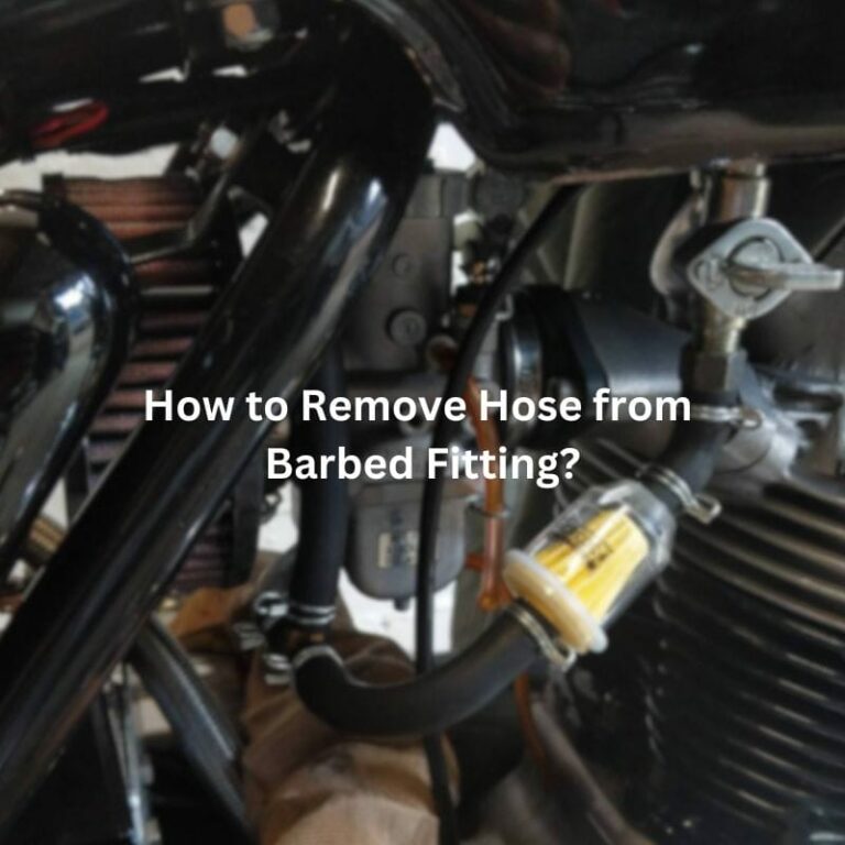
How to Remove a Stuck Hose Barb
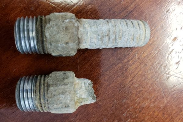
Removing a stuck hose barb can be challenging but with the right techniques, it can be done effectively:
Heat Application:
Process: Gently heat the surrounding area of the hose barb fitting using a heat gun or torch. Heat helps to expand the metal slightly, which can loosen the grip of corrosion or adhesive that may be holding the fitting in place.
Caution: Apply heat evenly and avoid excessive heating to prevent damage to surrounding components or hoses.
Penetrating Oil:
Application: Apply a generous amount of penetrating oil around the base of the hose barb where it meets the fitting. Allow the oil to soak in overnight or for several hours.
Purpose: Penetrating oil helps to lubricate and penetrate between the threads, loosening the stuck fitting over time.
Use of Tools:
Tools Needed: Use a pair of locking pliers, an adjustable wrench, or a specialized hose barb removal tool designed to grip the fitting securely.
Technique: Grip the hose barb firmly with the tool and apply steady, even pressure while twisting gently. This helps to break the bond between the fitting and the surrounding components.
Precaution: Avoid excessive force, which can damage the hose or fitting. Gradually increase pressure if necessary, but always prioritize gentle, controlled movements.
Cutting Method (Last Resort):
Approach: If all other methods fail, consider cutting the hose near the base of the barb using a sharp utility knife or hose cutter.
Safety: Exercise caution to avoid damaging the hose barb fitting or other nearby components.
Note: Cutting should be a last resort as it may necessitate replacing the hose and potentially the fitting, depending on the extent of damage.
Common Mistakes and How to Avoid Them
Over-tightening:
Mistake: Applying excessive torque to hose barb fittings can distort threads, crack components, or cause damage to the mating surfaces.
Prevention: Always adhere to the manufacturer’s recommended torque specifications when tightening hose barb fittings. Use a calibrated torque wrench to achieve the correct torque without over-stressing the components.
Incomplete Cleaning:
Mistake: Neglecting to thoroughly clean threads and mating surfaces before applying sealant can lead to poor adhesion and potential leaks.
Prevention: Before applying any sealant, ensure that all surfaces are clean, dry, and free of dirt, oil, or residue. Use appropriate cleaning agents and methods to remove contaminants effectively.
Using Wrong Sealant Type:
Mistake: Selecting a sealant that is incompatible with the materials or conditions of the application can result in ineffective sealing and system failures.
Prevention: Always verify the compatibility of the sealant with the specific materials (e.g., metals, plastics) and environmental conditions (e.g., temperature, chemical exposure) of your application. Refer to manufacturer guidelines and technical data sheets to confirm suitability before application.
Improper Application Technique:
Mistake: Rushing through the application process or applying sealant unevenly can lead to uneven seals, leaks, or inadequate bonding.
Prevention: Take time to apply sealants carefully and methodically. Follow the recommended procedures provided by the manufacturer, including proper mixing (if applicable), application techniques (e.g., brushing, spreading), and curing times. Ensure even coverage and avoid excess sealant that could interfere with assembly or compromise the seal’s integrity.
Conclusion
In selecting the best hose barb sealant, it’s crucial to prioritize compatibility with materials, environmental conditions, and ease of application. Following manufacturer guidelines for torque specifications and ensuring thorough surface cleaning before application helps prevent common pitfalls like over-tightening and inadequate adhesion. By staying informed and adopting best practices, you can optimize sealant selection and application processes, ensuring robust performance and longevity in their operations.
FAQ
A hose barb sealant is a substance applied to threaded or mating surfaces of hose barb fittings to create a tight seal, preventing leaks in fluid handling systems.
Consider the materials of your fittings and hoses, environmental conditions (such as temperature and chemical exposure), and ease of application. Match these factors with the sealant’s specifications for best results.
It depends on the type of sealant. Liquid sealants and thread seal tapes can sometimes be reapplied if removed carefully and surfaces are cleaned properly. Anaerobic sealants typically cure and bond permanently.
Use solvents or cleaners appropriate for the sealant type to dissolve and remove old residue. Mechanical methods like scraping or wire brushing may also be necessary.
Check for proper application techniques and ensure correct torque settings during assembly. Reapplying sealant or tightening fittings to recommended specifications may resolve the issue.
Not all sealants are suitable for food-grade applications. Look for sealants specifically rated and approved for use with food-contact surfaces if required for your application.


