Tri-Clamp Sizing 101 Everything You Need to Know banner

Tri-Clamp Sizing 101: Everything You Need to Know

Tri-clamps, also known as sanitary clamps, are essential components in a variety of industries where hygiene and efficiency are paramount. These fittings are commonly used in systems that require a high level of cleanliness, such as food and beverage processing, pharmaceuticals, and biotechnology. Tri-Clamps consist of three main parts: the clamp itself, a gasket, and a ferrule. Together, they create a secure, leak-proof connection between pipes and other components, ensuring smooth and uninterrupted flow.

Understanding Tri-Clamps

Definition and Purpose

A Tri-Clamp, also known as a sanitary clamp or tri-clover clamp, is a specialized fitting designed to provide a secure, leak-proof connection between pipes and other components in systems where hygiene and efficiency are critical. These fittings are particularly prevalent in industries such as food and beverage processing, pharmaceuticals, and biotechnology, where maintaining a sterile environment and ensuring seamless operation are paramount.

The primary purpose of a Tri-Clamp is to facilitate easy assembly and disassembly of pipe systems while ensuring a tight seal to prevent leaks and contamination. Tri-Clamps are essential for applications where regular cleaning, maintenance, or changes to the system are required. They allow for quick adjustments and replacements without the need for extensive downtime or complicated procedures, making them ideal for industries with stringent cleanliness standards.

Tri-Clamp Types

Components and Construction

Main Parts: Clamp, Gasket, and Ferrule

A typical Tri-Clamp assembly consists of three main components:

Clamp: The clamp is the external part that wraps around the pipe and the ferrule, securing them together. It usually features a hinged design with a tightening mechanism, such as a screw or latch, that allows for easy adjustment and secure fastening. The clamp ensures that the ferrule and gasket remain in place, creating a tight seal.

Gasket: The gasket is a crucial component that provides the sealing function within the Tri-Clamp assembly. Made from materials like rubber, silicone, or PTFE, the gasket compresses between the ferrule and the clamp, creating a leak-proof barrier. The choice of gasket material depends on the application’s requirements, including temperature, pressure, and chemical compatibility.

Ferrule: The ferrule is a ring-like component that fits over the end of the pipe. It is designed to create a smooth, even surface for the gasket to seal against. The ferrule is typically made from stainless steel, which provides durability and resistance to corrosion. Ferrules come in various sizes and configurations to match different pipe diameters and application needs.

Materials Used and Their Implications

Tri-Clamps are commonly made from high-quality materials to ensure durability, reliability, and resistance to environmental factors. The most common materials used include:

Stainless Steel: This is the most prevalent material for Tri-Clamps due to its excellent resistance to corrosion, high temperatures, and mechanical stress. Stainless steel grades such as 304 and 316 are frequently used, with 316 being preferred for more demanding applications due to its superior resistance to aggressive chemicals and extreme conditions.

Rubber and Elastomers: Gaskets are often made from rubber or elastomers such as EPDM, silicone, or nitrile. These materials are chosen based on their ability to maintain flexibility, resist compression set, and withstand the specific temperature and chemical conditions of the application.

PTFE (Polytetrafluoroethylene): PTFE gaskets are used in applications requiring high chemical resistance and low friction. PTFE is known for its ability to handle extreme temperatures and aggressive chemicals without degrading.

The choice of materials in a Tri-Clamp assembly directly impacts its performance, longevity, and suitability for different applications. For instance, stainless steel Tri-Clamps are ideal for high-pressure and high-temperature environments, while PTFE gaskets are suited for chemically aggressive substances.

Tri-Clamp Sizing Basics

Standard Sizes and Dimensions

Tri-Clamps are available in a range of standard sizes to accommodate various pipe diameters and system requirements. The sizing is typically denoted by the nominal diameter of the pipe that the clamp fits around. Common sizes include 1.5”, 2”, 2.5”, 3”, 4”, 6”, and up to larger diameters depending on the application. Each size corresponds to a specific outer diameter of the pipe and ferrule, ensuring compatibility across different systems.

Overview of Standard Sizes:

1.5” Tri-Clamp: Often used in smaller systems or where space is limited. Suitable for smaller pipes and low-to-moderate flow applications.

2” Tri-Clamp: A versatile size for many standard applications, including medium-sized pipes and moderate flow systems.

2.5” Tri-Clamp: Provides a larger connection for systems requiring higher flow rates or slightly larger pipes.

3” Tri-Clamp: Commonly used in larger systems, providing a robust connection for higher flow and pressure applications.

4” Tri-Clamp and Larger: Used in industrial applications where large volumes of fluids are handled, requiring more significant connections and robust fittings.

Measurement Guidelines for Each Component

Pipe Diameter: To determine the appropriate Tri-Clamp size, measure the outer diameter of the pipe accurately. This measurement is crucial for selecting the correct ferrule size and ensuring a proper fit. Use calipers or a pipe measuring tape to obtain precise dimensions.

Ferrule Dimensions: The ferrule should match the outer diameter of the pipe it is connecting. Ensure that the ferrule’s outer diameter corresponds to the nominal size of the Tri-Clamp. The ferrule’s thickness and length also play a role in the overall fit, so measure these dimensions carefully.

Clamp Size: The clamp itself should be sized to fit around the ferrule and pipe combination securely. Ensure that the clamp’s inner diameter matches the ferrule’s outer diameter and that it provides adequate compression on the gasket to form a leak-proof seal.

Gasket Size: The gasket should be slightly larger in diameter than the ferrule’s outer diameter to ensure a proper seal. Measure the gasket’s inner and outer diameters to ensure it fits snugly between the ferrule and the clamp.

Choosing the Right Size

Selecting the correct Tri-Clamp size is essential for maintaining system efficiency and safety. Several factors should be considered:

Pipe Diameter: The most critical factor is the diameter of the pipe. Ensure that the Tri-Clamp size matches the pipe’s outer diameter and the ferrule’s size. This ensures a secure fit and prevents leaks.

System Pressure: Different applications require different pressure ratings. Ensure that the selected Tri-Clamp can handle the system’s pressure requirements. Higher-pressure systems may require larger clamps or additional support to maintain integrity.

Flow Requirements: The size of the Tri-Clamp affects the flow rate through the system. Larger clamps allow for higher flow rates, while smaller clamps are suited for lower flow applications. Ensure that the chosen size meets the flow requirements of your system without causing restrictions or flow issues.

Compatibility with Other Components: Ensure that the Tri-Clamp size is compatible with other components in the system, such as hoses, valves, and fittings. Proper alignment and compatibility are essential for a functioning system.

Material Considerations: The material of the Tri-Clamp should match the requirements of the application. For example, stainless steel is ideal for high-pressure and high-temperature applications, while other materials may be suitable for less demanding environments.

Application-Specific Requirements: Different industries have specific standards and requirements for Tri-Clamp sizing. For instance, the food and beverage industry may have specific sanitary standards that must be met. Ensure that the Tri-Clamp size and material meet these industry standards.

Common Sizing Mistakes and How to Avoid Them

Overlooking Tolerances

Importance of Accounting for Tolerances in Manufacturing

When selecting Tri-Clamps, it’s crucial to consider manufacturing tolerances. Tolerances refer to the allowable variations in dimensions due to the manufacturing process. These variations can affect the fit and function of Tri-Clamps, potentially leading to issues such as leaks or improper seals.

Manufacturers produce Tri-Clamps to specific standards, but even with precise manufacturing, slight variations can occur. For instance, the outer diameter of a pipe may vary slightly from its nominal size due to tolerances in the pipe’s production. Similarly, ferrules and gaskets are subject to tolerances that can impact their fit within the clamp assembly.

To avoid issues arising from tolerances, ensure that your measurements are as precise as possible. Always account for these variations when selecting your Tri-Clamp size. It’s also advisable to use clamps and gaskets from the same manufacturer to ensure compatibility, as different manufacturers may have slightly different tolerances.

Tri-Clamp Sizing Applications

Incorrect Measurements

Common Errors in Measuring and How to Correct Them

Accurate measurements are fundamental to selecting the right Tri-Clamp size. Common measurement errors include:

Using Incorrect Tools: Using inappropriate measuring tools can lead to inaccurate dimensions. Ensure you use calipers or a pipe measuring tape for precise measurements. Avoid using tape measures that are not designed for this purpose, as they may provide less accurate results.

Measuring Pipe Diameter Incorrectly: When measuring the outer diameter of a pipe, ensure you measure at multiple points around the pipe to account for any irregularities. Pipes can sometimes have slight variations in diameter, so measuring at several points helps ensure accuracy.

Ignoring Pipe Wall Thickness: The wall thickness of the pipe can affect the overall size of the Tri-Clamp required. Ensure that you measure the pipe’s outer diameter accurately, including its wall thickness, to select the correct clamp and ferrule size.

Not Measuring Ferrule and Gasket Sizes: Ensure that you measure both the ferrule and gasket accurately. The ferrule’s outer diameter should match the clamp’s inner diameter, and the gasket should be sized appropriately to fit snugly between the ferrule and clamp.

To correct these errors, use precise measuring instruments, measure multiple times to confirm accuracy, and consult sizing charts or guidelines provided by manufacturers. If in doubt, consult with a professional or manufacturer for assistance.

Choosing Incompatible Sizes

Risks of Using Mismatched Tri-Clamp Sizes

Using mismatched Tri-Clamp sizes can lead to several risks and issues:

Leaks: Mismatched sizes can result in gaps between the ferrule and clamp or between the gasket and ferrule. This can cause leaks, which can lead to contamination, loss of fluid, and potential safety hazards.

Reduced System Efficiency: An incorrect size can cause restrictions or blockages in the system, affecting flow rates and overall efficiency. This can result in decreased performance and potential damage to the system.

Increased Maintenance Costs: Using incompatible sizes may lead to frequent maintenance and repairs. Leaks and inefficiencies can cause additional wear and tear on the system, increasing maintenance costs and downtime.

Safety Hazards: In systems handling hazardous or high-pressure fluids, using the wrong size Tri-Clamp can pose safety risks. Leaks or system failures can lead to dangerous conditions for operators and damage to equipment.

To avoid these risks, always ensure that the Tri-Clamp size matches the pipe and ferrule dimensions accurately. Verify that all components, including the clamp, ferrule, and gasket, are compatible and correctly sized for the application. Consulting with suppliers or manufacturers for guidance on sizing and compatibility can also help prevent issues.

Tri-Clamp Sizing for Different Applications

Food and Beverage Industry

Specific Requirements and Standards

In the food and beverage industry, maintaining sanitary conditions is paramount, making the correct sizing and selection of Tri-Clamps critical. This industry requires fittings that can withstand frequent cleaning, high temperatures, and exposure to various chemicals, all while preventing contamination. The key standards that govern the use of Tri-Clamps in this industry include the 3-A Sanitary Standards and the FDA (Food and Drug Administration) regulations.

3-A Sanitary Standards: These standards are designed to ensure that equipment used in food processing is cleanable, corrosion-resistant, and safe for contact with food. Tri-Clamps used in the food and beverage industry must comply with these standards, which specify requirements for material, surface finish, and ease of cleaning. Typically, 316L stainless steel is preferred due to its superior corrosion resistance and ease of cleaning.

FDA Compliance: All materials in contact with food or beverages must be FDA-approved. This includes not only the Tri-Clamp but also the gaskets and seals. Silicone and PTFE gaskets are commonly used because they meet FDA requirements for food safety.

Correct Sizing: The correct sizing of Tri-Clamps in the food and beverage industry is crucial to maintaining product integrity. Oversized or undersized clamps can lead to leaks, contamination, or inefficient cleaning processes. Properly sized Tri-Clamps ensure a tight seal, prevent bacterial growth, and allow for thorough cleaning and sanitization.

Tri-Clamp Sizing

Pharmaceuticals and Biotech

Sanitary Considerations and Compliance

In the pharmaceutical and biotech industries, the need for sterility and contamination control is even more stringent. Tri-Clamps used in these applications must meet rigorous standards to ensure that they do not compromise the safety or efficacy of the products being processed.

USP Class VI Compliance: The materials used in Tri-Clamps, especially the gaskets, must meet USP Class VI standards. This certification ensures that the materials are biocompatible and do not leach harmful substances into the product. PTFE and EPDM are common gasket materials that meet these requirements.

BPE (Bioprocessing Equipment) Standards: The ASME BPE standards specifically address the requirements for equipment used in bioprocessing and pharmaceutical manufacturing. Tri-Clamps must meet these standards, which include stringent requirements for surface finish, material, and cleanability. A surface finish with a roughness average (Ra) of 20 microinches or better is often required to minimize the risk of bacterial adhesion.

Correct Sizing: In pharmaceutical and biotech applications, precise sizing is critical to maintaining a sterile environment. Incorrectly sized clamps can create crevices where contaminants can accumulate, leading to product contamination. The correct Tri-Clamp size ensures a secure, leak-proof connection that is easy to sterilize and maintain.

Other Industries

Chemical Processing: In chemical processing, Tri-Clamps are used in systems that handle aggressive chemicals, high pressures, and extreme temperatures. The sizing of Tri-Clamps in this industry must account for these factors to ensure that the fittings can withstand the operating conditions without failing. In many cases, larger clamps made from specialized materials like Hastelloy or Monel may be required.

Dairy Industry: Similar to the food and beverage industry, the dairy industry requires Tri-Clamps that meet sanitary standards. However, the sizing in dairy applications often involves larger diameter pipes to handle the high flow rates needed for milk and other dairy products. The correct sizing ensures that the system can handle the volume without compromising on cleanliness or efficiency.

Brewing and Distilling: In brewing and distilling, Tri-Clamps are used to connect equipment like fermenters, stills, and transfer lines. The sizing must accommodate the specific needs of the process, such as high flow rates and temperature changes. Stainless steel Tri-Clamps with appropriate gaskets are commonly used to ensure durability and a proper seal in these applications.

Water Treatment: Tri-Clamps are also used in water treatment systems, where they connect pipes and components involved in filtration, chemical dosing, and other processes. The sizing requirements in this industry vary based on the system design and the types of fluids being handled. Properly sized Tri-Clamps help maintain the integrity of the water treatment process, ensuring that there are no leaks or contamination.

Conclusion

For accurate Tri-Clamp sizing, always ensure precise measurements and account for manufacturing tolerances. Verify that the sizes of clamps, ferrules, and gaskets match the dimensions of the pipes and fittings they connect. Consider the specific needs of your application, including pressure, flow rates, and regulatory standards, to choose the appropriate size and material. For complex requirements or uncertainties, don’t hesitate to consult with experts or refer to additional resources.


FAQ

What is a Tri-Clamp?

A Tri-Clamp is a type of sanitary fitting used to connect pipes and equipment in industries like food and beverage, pharmaceuticals, and biotech. It consists of a clamp, a ferrule, and a gasket to ensure a secure, leak-proof connection.

How do I measure for the correct Tri-Clamp size?

Measure the outer diameter of the pipe and the ferrule accurately. The Tri-Clamp size should match the ferrule’s outer diameter, and the gasket should fit snugly between the ferrule and clamp.

What materials are Tri-Clamps typically made from?

Tri-Clamps are commonly made from stainless steel (like 316L) for durability and corrosion resistance. Gaskets can be made from materials like silicone, PTFE, or EPDM, depending on the application.

Why is correct sizing important for Tri-Clamps?

Correct sizing ensures a proper fit, prevents leaks, maintains system efficiency, and meets regulatory standards. Incorrect sizing can lead to leaks, contamination, or system inefficiencies.

How can I avoid common sizing mistakes?

To avoid mistakes, use precise measuring tools, account for manufacturing tolerances, and ensure compatibility of all components. Double-check measurements and consult manufacturer guidelines if needed.

When should I consult with an expert for Tri-Clamp sizing?

Consult an expert if you have complex requirements, face difficulties in measurement, or need to ensure compliance with industry-specific standards.

Air Conditioning Hoses Fail banner

Air Conditioning Hoses Fail: Understanding the Warning Signs

Air conditioning hoses are crucial components in an automotive AC system. They are responsible for transporting refrigerant and other fluids between various parts of the system, such as the compressor, condenser, and evaporator. These hoses ensure that the refrigerant can circulate effectively, enabling the AC system to cool the vehicle’s interior efficiently. Without properly functioning hoses, the AC system cannot perform optimally, leading to potential breakdowns and decreased comfort.

Understanding Air Conditioning Hoses

The function of AC Hoses

Role in the AC System

Transporting Refrigerant: Air conditioning hoses play a critical role in moving refrigerant between the various components of the AC system. This refrigerant absorbs heat from the interior of the vehicle and releases it outside, which is essential for cooling the cabin.

Maintaining Pressure and Flow: Hoses ensure that refrigerant flows at the correct pressure and volume. Proper flow is crucial for the system’s efficiency and overall performance.

Providing Flexibility: They accommodate the movement and vibrations of the vehicle, allowing the AC system to remain functional despite the constant motion and changes in temperature.

Different Types of AC Hoses and Their Functions

High-Pressure Hoses: These hoses transport refrigerant from the compressor to the condenser. They are built to withstand high pressure and temperatures.

Low-Pressure Hoses: These carry refrigerant from the evaporator back to the compressor. They operate under lower pressure and are designed for different temperature conditions compared to high-pressure hoses.

Discharge Hoses: These connect the compressor to the condenser and are responsible for carrying the hot, high-pressure refrigerant.

Suction Hoses: These link the evaporator to the compressor and handle the cooler, low-pressure refrigerant.

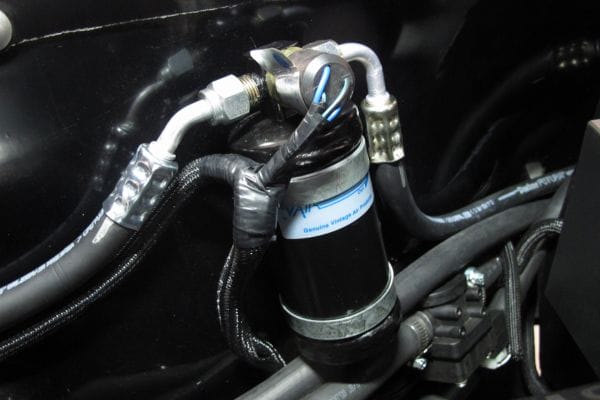
Air Conditioning Hoses maintain

B. Components of the AC System

Overview of Related Components

Compressor: Often referred to as the heart of the AC system, the compressor pumps refrigerant through the system, increasing its pressure and temperature. It is crucial for initiating the cooling process.

Condenser: Located at the front of the vehicle, the condenser cools the high-pressure refrigerant coming from the compressor, turning it from a gas into a liquid.

Evaporator: Inside the vehicle’s cabin, the evaporator absorbs heat from the air, causing the refrigerant to evaporate into a gas. This process cools the air that is blown into the cabin.

How Hoses Interact with These Components

Connection to the Compressor: High-pressure hoses connect the compressor to the condenser, transporting the pressurized refrigerant.

Link to the Condenser: From the condenser, refrigerant moves through the high-pressure hose to the expansion valve or orifice tube before reaching the evaporator.

Interaction with the Evaporator: Low-pressure hoses transport the refrigerant from the evaporator back to the compressor, completing the cycle.

System Integration: Hoses must be properly connected to ensure that refrigerant flows seamlessly through these components, maintaining the AC system’s efficiency and effectiveness.

Common Warning Signs of a Failing AC Hose

A. Visible Cracks and Leaks

How Cracks and Leaks Develop

Wear and Tear: Over time, AC hoses can deteriorate due to exposure to extreme temperatures, UV radiation, and physical abrasion. This wear and tear can cause the rubber or synthetic material to crack.

Pressure and Temperature Stress: Repeated exposure to high pressure and temperature fluctuations can weaken hose materials, leading to splits or leaks.

Chemical Damage: Exposure to chemicals or oil can degrade hose materials, resulting in cracks or leaks.

Identification: Where to Check for Visible Damage

Surface Inspection: Check the length of the hoses for visible cracks, bulges, or splits. Inspect the areas where the hose is connected to other components for signs of leakage.

Connection Points: Look closely at the connections to the compressor, condenser, and evaporator. Leaks often occur at these joints.

Under Vehicle: Examine the hoses underneath the vehicle for any signs of drips or puddles, which can indicate a leak.

Effect on the Overall AC System

Reduced Efficiency: Leaks or cracks can cause refrigerant loss, leading to decreased cooling efficiency and potential system failure.

System Damage: Prolonged leakage can cause damage to other AC components due to insufficient refrigerant, affecting overall performance and leading to costly repairs.

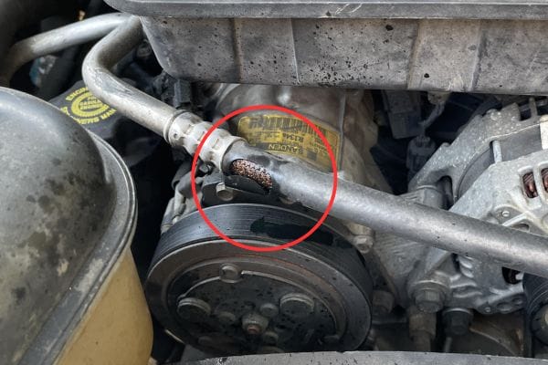
Air Conditioning Hoses fail

B. Loss of Cooling Efficiency

Symptoms of Reduced Cooling Performance

Insufficient Cooling: The AC system may not cool the cabin as effectively, resulting in warmer air blowing from the vents.

Temperature Fluctuations: Inconsistent or erratic cooling performance can be a sign of underlying hose issues.

How to Test for Efficiency Issues

Check Temperature Output: Use a thermometer to measure the air temperature coming out of the vents. Compare this with expected temperatures for the vehicle’s AC system.

Evaluate System Pressure: Use a pressure gauge to check the refrigerant pressure in both high and low-pressure sides of the system.

Potential Causes Related to Hose Problems

Refrigerant Loss: Leaky or damaged hoses can cause refrigerant to escape, leading to reduced cooling efficiency.

Pressure Imbalances: Hoses that are cracked or blocked can disrupt the proper flow and pressure of the refrigerant, affecting system performance.

C. Unusual Noises

Common Noises Indicating Hose Failure

Hissing: A hissing sound can indicate refrigerant escaping from a damaged hose or connection.

Whistling: Whistling noises may suggest air or refrigerant is being forced through a partially blocked or damaged hose.

How to Pinpoint the Source of the Noise

Listen Carefully: Pay attention to when and where the noises occur (e.g., during acceleration or while the AC is on).

Inspect the Hoses: Locate the source of the noise by visually inspecting and feeling along the hoses to find any irregularities or areas of damage.

Consequences for the AC System

Performance Issues: Unusual noises can indicate that the AC system is not operating as it should, potentially leading to reduced cooling efficiency.

Potential Damage: Ignoring these noises can lead to further damage to the AC system components due to improper refrigerant flow.

D. AC System Pressure Issues

Signs of Pressure Fluctuations or Low Pressure

Fluctuating Pressure: Inconsistent pressure readings can indicate problems with the hoses or other AC components.

Low Pressure: Persistently low pressure may signal a refrigerant leak or a blockage within the hose.

Tools and Methods to Measure System Pressure

Pressure Gauges: Use an AC manifold gauge set to measure the refrigerant pressure on both the high and low sides of the system.

Professional Diagnostic Tools: Advanced tools like electronic leak detectors can provide more precise measurements and detect leaks.

How Pressure Issues Relate to Hose Health

Flow Disruption: Pressure issues often result from hose damage or blockages, disrupting the flow of refrigerant and affecting system efficiency.

System Imbalance: Improper pressure can lead to an imbalance in the AC system, potentially causing further component damage.

E. Increased Refrigerant Consumption

Frequency of Refrigerant Refills

Frequent Refills: Regularly needing to add refrigerant may indicate that there is a leak or inefficiency in the AC system.

Gradual Decline: A gradual decrease in refrigerant levels over time is a common sign of hose issues.

How to Check for Leaks or Inefficiencies

Leak Detection: Use dye or electronic leak detectors to find where refrigerant might be escaping.

System Inspection: Check all hoses, connections, and components for signs of leakage or damage.

Long-Term Effects on the AC System

Increased Costs: Frequent refrigerant refills can become costly and indicate a need for more significant repairs.

System Wear: Constant low refrigerant levels can lead to increased wear on the compressor and other components, potentially causing system failure.

Diagnosing and Repairing AC Hose Issues

A. Diagnostic Tools and Methods

Visual Inspection

Surface Examination: Carefully inspect the entire length of each hose for visible signs of wear, such as cracks, bulges, or splits.

Connection Points: Examine the areas where hoses connect to other components for signs of leakage or damage. Look for oil spots or refrigerant residue.

Flexibility Check: Gently squeeze and bend the hoses to detect any stiffness or irregularities that might indicate internal damage.

Pressure Gauges

Manifold Gauge Set: Connect the manifold gauge set to the service ports on the AC system to measure high and low-pressure readings. Compare these readings to the manufacturer’s specifications.

Pressure Variations: Look for fluctuations or consistently low or high pressure, which can indicate issues with the hoses or other components.

Leak Detectors

Electronic Leak Detectors: Use electronic devices that can sense refrigerant gas leaks by detecting the specific chemical signatures of refrigerants.

UV Dye and Black Light: Inject UV dye into the AC system and use a black light to trace any leaks, as the dye will glow under UV light.

Soap Solution: Apply a soapy water solution to hose connections and look for bubbles that indicate escaping refrigerant.

B. Temporary Fixes

Methods

Sealant Tapes: Use rubber or silicone sealant tapes to cover small leaks or cracks as a short-term solution.

Clamps and Patches: Apply hose clamps or repair patches to temporarily seal damaged areas and prevent further leaks.

Refrigerant Additives: Some refrigerant additives are designed to temporarily seal minor leaks; however, these should not replace proper repairs.

Limitations

Temporary Nature: These fixes are not permanent and may only provide a brief respite before issues reoccur.

Potential for Further Damage: Temporary fixes can mask underlying problems, potentially leading to more significant damage or system failure if not addressed properly.

Efficiency Issues: Temporary solutions might not fully restore the system’s efficiency, leading to continued performance problems.

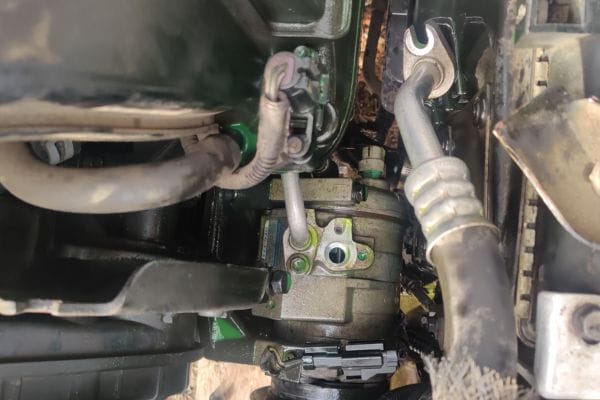
Air Conditioning Hoses broken

C. Professional Repair and Replacement

When to Seek Professional Help

Persistent Issues: If temporary fixes do not resolve the problem or if new symptoms arise, it’s time to consult a professional.

Complex Problems: For extensive damage, recurring leaks, or if multiple components are affected, professional expertise is required to address the issues properly.

System Diagnosis: When the source of the problem is not clear, a professional can provide a comprehensive diagnostic to pinpoint and resolve the issue.

Repair Options

Hose Replacement: Replacing damaged hoses with new, high-quality ones to ensure proper functionality and system efficiency.

Component Repair: Repairing or replacing other affected components, such as the compressor or condenser, if damage extends beyond the hoses.

System Flush and Refill: Flushing the AC system to remove contaminants and refilling with fresh refrigerant to restore optimal performance.

Costs and Considerations

Repair Costs: Costs can vary depending on the extent of the damage, the type of repair needed, and labor rates. Replacing hoses typically ranges from $150 to $400, depending on the vehicle and parts.

Replacement Costs: Full replacement of damaged components or the AC system can be more expensive, potentially ranging from $500 to $2,000 or more.

Long-Term Savings: Investing in professional repair ensures proper and lasting fixes, potentially saving money in the long run by preventing further damage and maintaining system efficiency.

Preventive Maintenance for AC Hoses

A. Regular Inspections

Frequency

Routine Checks: Perform visual inspections of AC hoses every 6 to 12 months, especially before and after extreme temperature changes or long drives.

Seasonal Inspections: Conduct thorough inspections at the start of the cooling and heating seasons to ensure hoses are in good condition.

Checklist

Visual Condition: Check for cracks, bulges, or wear on the hose surface. Ensure there are no visible signs of leakage.

Connection Points: Examine the hose connections for any signs of looseness or leakage.

Flexibility: Ensure hoses remain flexible and do not show signs of brittleness or stiffness.

Pressure Testing: Use a pressure gauge to check for proper pressure levels in the AC system.

B. Proper Usage and Care

Handling

Avoid Sharp Objects: Keep hoses away from sharp edges or objects that could cause punctures or abrasions.

Protect from Heat: Ensure hoses are not exposed to excessive heat sources, which can degrade their material.

Secure Installation: Properly secure hoses to prevent movement or rubbing that could lead to wear.

Storage

Clean Storage: Store hoses in a clean, dry area to avoid contamination and damage.

Avoid Kinking: Coil hoses loosely without kinking to maintain their integrity and flexibility.

Cover Hoses: Use protective covers or bags to shield hoses from dust and debris if they are temporarily removed.

C. Replacing Old Hoses

Signs of Aging

Cracking or Drying: Look for visible signs of cracking, drying, or hardening of the hose material, indicating that the hose is past its prime.

Leaking: Persistent leaks at connection points or along the hose length suggest it may need replacement.

Reduced Flexibility: Hoses that have lost their flexibility and become rigid may need to be replaced to prevent system issues.

Choosing New Hoses

Compatibility: Ensure the new hoses are compatible with your vehicle’s AC system specifications and refrigerant type.

Quality: Opt for high-quality hoses from reputable manufacturers to ensure durability and performance.

Fit and Installation: Verify that the hoses fit correctly and are easy to install, considering factors like length, diameter, and connector types.

Warranty: Consider hoses with a warranty for added assurance and protection against defects.

Conclusion

Taking proactive steps to monitor and maintain your AC system not only ensures comfort but also safeguards your investment in vehicle maintenance. Stay vigilant, address any signs of trouble promptly, and consult professionals when needed to keep your air conditioning system running at its best.


FAQ

What are the common signs of a failing AC hose?

Common signs include visible cracks and leaks, reduced cooling efficiency, unusual noises like hissing or whistling, pressure fluctuations, and increased refrigerant consumption.

How often should I inspect my AC hoses?

It’s recommended to inspect AC hoses every 6 to 12 months, especially before and after extreme temperature changes or long drives.

What tools are needed to diagnose AC hose issues?

Diagnostic tools include visual inspection techniques, pressure gauges, leak detectors, and UV dye for finding refrigerant leaks.

Can I temporarily fix a leaking AC hose?

Yes, temporary fixes include using sealant tapes, clamps, and refrigerant additives. However, these are not long-term solutions and proper repairs should be made as soon as possible.

When should I replace my AC hoses?

Replace AC hoses if they show signs of cracking, drying, leaking, or reduced flexibility. Old hoses that no longer perform effectively should be replaced to avoid system issues.

What should I consider when buying new AC hoses?

Consider compatibility with your vehicle’s AC system, the quality of the hose, correct fit and installation, and any warranties offered for added protection.

Hydraulic Fluid Leaks banner

Hydraulic Fluid Leaks: Causes, Consequences, and Solutions

Leaks not only impact the performance and efficiency of the system but also pose significant safety risks, environmental hazards, and financial costs. Uncontrolled leaks can lead to decreased hydraulic pressure, causing machinery to operate inefficiently or even fail. Additionally, they can result in safety incidents, such as slip hazards and fire risks, and contribute to environmental contamination.

Understanding Hydraulic Fluid Leaks

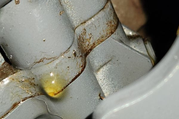
Fluid leaks refer to the unintentional escape of hydraulic fluid from a hydraulic system. These leaks occur when hydraulic fluid, which is essential for transferring force within the system, escapes through damaged or improperly sealed components. Leaks can range from small, barely noticeable drips to significant spills that compromise the system’s operation and safety. The causes of leaks can be varied, including physical damage, degradation of system components, and improper installation.

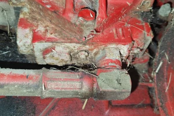
Topa Fluid Leaks

Overview of Hydraulic Fluid Systems and Their Components

Hydraulic fluid systems are designed to transmit energy through fluid under pressure. The primary components of these systems include:

Hydraulic Fluid: The medium through which force is transmitted. It must be clean, properly maintained, and free of contaminants to ensure efficient operation.

Pumps: These components pressurize the hydraulic fluid, converting mechanical energy into hydraulic energy.

Actuators (Cylinders and Motors): These components use the pressurized fluid to perform work, such as moving or controlling machinery parts.

Hoses and Tubing: Flexible or rigid conduits that transport hydraulic fluid throughout the system.

Valves: Devices that control the flow and direction of hydraulic fluid, regulating system pressure and movement.

Fittings and Connectors: Components that join hoses and tubing to various parts of the system, ensuring a secure and leak-free connection.

Filters: These remove contaminants from the hydraulic fluid, protecting the system from damage and maintaining performance.

Typical Locations Where Leaks Occur

Leaks can happen at various points in a hydraulic system. Common locations include:

Fittings and Connectors: These are prone to leaks due to improper tightening, wear, or damage. Seals within fittings can degrade over time, leading to fluid escape.

Hoses and Tubing: Flexible hoses and rigid tubes can develop leaks due to abrasion, chemical exposure, or pressure fluctuations. Cracks and tears in hoses are common sources of leaks.

Seals and Gaskets: Seals and gaskets are crucial for preventing fluid leakage at junctions and interfaces. They can fail due to age, contamination, or incorrect installation, allowing fluid to leak.

Pumps and Actuators: Leaks can occur around seals and joints in pumps and actuators, often resulting from wear and tear or maintenance issues.

Valves: Leakage can happen around the valve stems or in the valve body due to damaged seals or internal wear.

Causes of Fluid Leaks

a. Component Wear and Tear

Description of Common Components Prone to Wear

Hydraulic systems rely on various components that are susceptible to wear over time. Key components include:

Seals: Seals are used to prevent fluid from escaping at joints and interfaces. They can wear out due to pressure cycling, temperature extremes, or chemical interactions.

Hoses: Hydraulic hoses transport fluid under pressure and can degrade due to internal and external stresses. They are prone to damage from abrasion, bending, and high pressure.

Fittings: Fittings connect hoses and other components. They can wear out due to repeated connections and disconnections, leading to leaks at the connection points.

Factors Contributing to Wear

Several factors contribute to the wear and eventual failure of hydraulic components:

Pressure: High operating pressures exert significant stress on seals and hoses, accelerating wear. Frequent pressure surges or spikes can exacerbate this issue.

Temperature: Extreme temperatures can affect the material properties of seals and hoses. High temperatures can cause seals to harden and crack, while low temperatures can make them brittle and prone to failure.

Vibration: Constant vibration from machinery or pumps can lead to mechanical fatigue in hoses and fittings, causing premature wear and potential leaks.

Hose Fail environment

b. Improper Installation

Consequences of Incorrect Installation Techniques

Improper installation of hydraulic components can lead to a range of issues, including leaks. Consequences include:

Leakage: Incorrect installation techniques can result in inadequate sealing, leading to leaks. This can affect system performance and safety.

Reduced System Efficiency: Poorly installed components can disrupt fluid flow, leading to decreased efficiency and increased energy consumption.

Increased Maintenance Costs: Frequent repairs and replacements due to installation errors can increase maintenance costs and downtime.

Examples of Installation Errors

Common installation errors that can lead to leaks include:

Over-tightening: Excessive tightening of fittings can damage seals and threads, leading to leaks. Over-tightening can also cause stress fractures in hoses and connectors.

Misalignment: Misalignment of hoses and fittings can create stress points and lead to leaks. Proper alignment ensures that connections are secure and leak-free.

c. Damage and External Factors

Causes Such as Physical Damage

External factors can significantly impact the integrity of hydraulic components:

Physical Damage: Components can be damaged by impacts, abrasion, or collisions. For example, hoses can be cut or scratched by sharp objects, leading to leaks.

Chemical Exposure: Exposure to harsh chemicals or fluids can degrade materials used in hydraulic systems. For instance, certain chemicals can cause hoses to swell or soften, leading to leaks.

Environmental Conditions: Extreme weather conditions, such as high humidity, UV radiation, or temperature fluctuations, can affect hydraulic components. For example, UV exposure can deteriorate rubber hoses, while high humidity can lead to rust and corrosion in metal components.

Impact of External Factors on Hydraulic Components

External factors can lead to:

Material Degradation: Chemical exposure and environmental conditions can weaken materials, making them more susceptible to wear and failure.

Compromised Seals: Physical damage or environmental conditions can impair the effectiveness of seals, leading to leaks.

d. System Contamination

How Contaminants Affect Hydraulic Systems

Contaminants can have a detrimental effect on hydraulic systems. They can cause:

Abrasive Wear: Contaminants like dirt and debris can cause abrasive wear on internal components, leading to leaks and reduced efficiency.

Chemical Reactions: Contaminants can react with hydraulic fluid or component materials, leading to degradation and failure.

Types of Contaminants

Common types of contaminants include:

Dirt and Debris: Particulate matter can enter the system through unfiltered air or damaged components, causing abrasive wear and blockages.

Water: Water contamination can cause rust and corrosion in metal components and affect the fluid’s lubricating properties.

Chemicals: Chemical contaminants can interact with hydraulic fluid or component materials, leading to material degradation or chemical reactions.

Consequences of Hydraulic Fluid Leak

a. Decreased System Efficiency

Impact on Hydraulic Pressure and Overall Performance

Fluid leaks can significantly impair system efficiency by disrupting the intended pressure and flow within the hydraulic circuit. When fluid escapes from a leak, the system must work harder to maintain the required pressure, leading to:

Reduced Pressure: Loss of hydraulic fluid can cause a drop in system pressure, which impacts the ability of hydraulic components to perform effectively. This reduction can lead to sluggish operation or complete failure of hydraulic functions.

Erratic Performance: Leaks can cause fluctuations in pressure, leading to erratic performance of hydraulic machinery. This inconsistency affects precision and reliability in operations.

Examples of Reduced Efficiency in Various Applications

Manufacturing: In industrial machinery, such as presses or injection molding machines, reduced hydraulic pressure due to leaks can lead to inconsistent product quality and increased cycle times.

Construction: In construction equipment like excavators or loaders, leaks can reduce lifting capabilities and operational efficiency, causing delays and increasing project costs.

Hydraulic Fitting Fluid Leaks

b. Safety Hazards

Potential Safety Risks Associated with Hydraulic Fluid Leak

Fluid leaks pose several safety risks, including:

Fire Hazards: Many hydraulic fluids are flammable. Leaks can create a fire risk, especially in environments with high temperatures or sources of ignition.

Slip Hazards: Leaking hydraulic fluid can create slippery surfaces, increasing the risk of slips and falls. This is particularly dangerous in workplaces with high foot traffic.

Case Studies or Examples of Accidents Due to Leaks

Industrial Accident: In a manufacturing facility, a hydraulic leak caused a fire that resulted in significant damage to equipment and posed a serious safety risk to workers.

Construction Site Incident: At a construction site, a fluid leak led to a slip and fall accident, causing injuries to an employee and leading to costly medical expenses and downtime.

c. Increased Operational Costs

Cost Implications of Leaks

Hydraulic fluid leaks can lead to various financial impacts, including:

Repair Costs: Leaks require immediate repair to restore system functionality. The costs associated with diagnosing and fixing leaks can be significant, especially if they involve replacing components or extensive downtime.

Downtime: Leaks can cause machinery to be taken out of service, leading to operational delays and reduced productivity. The resulting downtime affects overall production schedules and can have a cascading effect on project timelines.

Long-Term Financial Impact on Operations

Increased Maintenance Costs: Frequent leaks and the associated repairs can lead to higher maintenance costs over time. Regular repairs and replacements can strain budgets and affect profitability.

Operational Inefficiencies: Persistent leaks lead to decreased system efficiency and higher energy consumption. The long-term impact on operational efficiency can result in increased costs and reduced competitiveness.

d. Environmental Impact

Environmental Risks and Pollution Concerns

Fluid leaks can have serious environmental consequences, including:

Soil and Water Contamination: Leaking hydraulic fluids can contaminate soil and water sources, leading to potential long-term environmental damage. Contaminated soil and water can affect plant and animal life and pose risks to human health.

Pollution: Spills and leaks contribute to pollution, which can lead to regulatory fines and damage to the company’s reputation. Environmental pollution can also have broader impacts on local ecosystems and communities.

Regulations and Standards Related to Hydraulic Fluid Management

Environmental Regulations: Various regulations govern the management and disposal of hydraulic fluids. Compliance with these regulations is crucial to avoid legal penalties and environmental damage. Examples include the Resource Conservation and Recovery Act (RCRA) in the U.S. and similar regulations in other countries.

Industry Standards: Adherence to industry standards for hydraulic fluid management helps mitigate environmental risks. Standards such as ISO 14001 for environmental management systems provide guidelines for reducing environmental impacts and improving sustainability.

Detecting Hydraulic Fluid Leak

a. Visual Inspections

Techniques for Spotting Leaks During Routine Checks

Visual inspections are a fundamental method for detecting fluid leaks. Effective techniques include:

Regular Walkthroughs: Conduct regular visual inspections of hydraulic systems during routine maintenance or operational checks. Look for signs of fluid accumulation, staining, or wetness around components.

System Monitoring: Inspect areas around hoses, fittings, seals, and connections for any visible signs of leakage. Pay close attention to potential problem areas, such as joints and bends.

Stains and Residues: Look for fluid stains or residues on machinery, floors, or nearby surfaces. These can indicate where the fluid is leaking and help trace the source of the leak.

Tools and Equipment Used for Visual Inspections

Inspection Mirrors: Small, handheld mirrors can help view difficult-to-access areas behind or under equipment.

Flashlights: Bright, focused lighting can illuminate dark areas and make it easier to spot leaks or fluid stains.

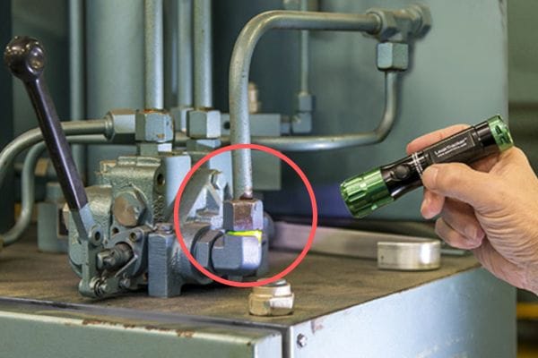
Leak Detection Dyes: Special dyes added to hydraulic fluids can make leaks more visible under UV light, aiding in detection.

b. Pressure Testing

Methods for Pressure Testing Hydraulic Systems

Pressure testing involves applying pressure to the hydraulic system to identify leaks. Common methods include:

Hydraulic Pressure Test: Increase the pressure in the system using a hydraulic pump while monitoring for pressure drops. A pressure drop indicates a potential leak.

Isolation Testing: Isolate sections of the hydraulic system and test each section separately. This method helps pinpoint the location of leaks by narrowing down the area under test.

System Bleed-Off Test: Allow the system to pressurize, then monitor the system as it depressurizes. A rapid or abnormal drop in pressure suggests a leak.

How Pressure Testing Helps Identify Leaks

Pressure testing helps detect leaks by:

Highlighting Weak Points: Applying pressure can cause leaks to become more apparent, especially if the leak is small or intermittent.

Locating Leaks: By isolating different parts of the system, pressure testing can help pinpoint the exact location of leaks, making it easier to address them.

c. Leak Detection Technologies

Overview of Advanced Leak Detection Technologies

Advanced leak detection technologies provide more precise and efficient methods for identifying fluid leaks. Key technologies include:

Ultrasonic Sensors: Ultrasonic sensors detect the sound of escaping fluids by converting high-frequency sound waves into audible signals. They can locate leaks by analyzing the frequency and intensity of the sound waves.

Advantages: Highly sensitive, can detect small leaks, and are effective in noisy environments.

Limitations: Requires calibration and may not be as effective in extremely noisy environments or where the leak is very small.

Dye Testing: Involves adding fluorescent dye to the hydraulic fluid, which becomes visible under UV light. This method helps to visually trace the path of the leak.

Advantages: Easy to use, provides a clear visual indication of leak paths, and is effective for pinpointing leaks in complex systems.

Limitations: May not be suitable for all types of hydraulic fluids and can be messy or require additional cleanup.

Infrared Thermography: Uses infrared cameras to detect temperature differences caused by fluid leaks. Leaking fluid can create temperature variations that are visible through thermal imaging.

Advantages: Non-contact method, can scan large areas, and identifies leaks based on temperature changes.

Limitations: Requires expertise to interpret thermal images and may be less effective in environments with uniform temperature distribution.

Acoustic Leak Detection: Uses microphones or acoustic sensors to detect the sound of fluid escaping. This method is similar to ultrasonic detection but focuses on lower-frequency sounds.

Advantages: Effective for detecting leaks in noisy environments and can be used in combination with other methods for enhanced accuracy.

Limitations: May require specialized equipment and training to use effectively.

Solutions and Preventive Measures

a. Repairing Hydraulic Fluid Leak

Step-by-Step Guide to Common Repair Techniques

Identify the Leak Source:

Use visual inspection, pressure testing, or advanced leak detection technologies to pinpoint the exact location of the leak.

Isolate the System:

Shut down the hydraulic system and relieve any residual pressure. This step ensures safety and prevents further leakage during repair.

Drain the Hydraulic Fluid:

Remove the hydraulic fluid from the affected area if necessary. This step might involve draining the entire system or just the section under repair.

Remove and Inspect Affected Components:

Disassemble the components where the leak is identified. Check for damage, wear, or contamination. Replace or repair damaged parts as needed.

Repair or Replace Components:

If the leak is due to a damaged seal, hose, or fitting, replace it with a new, compatible part. Ensure all replacement parts meet the specifications of the original components.

Reassemble and Test:

Reassemble the system, ensuring all connections are secure and components are properly aligned. Conduct a pressure test to confirm that the leak has been effectively repaired.

Refill and Inspect:

Refill the system with hydraulic fluid and check for any signs of leakage. Monitor the system closely during initial operation to ensure the repair is successful.

Tips for Selecting the Right Replacement Parts

Compatibility: Ensure that replacement parts are compatible with the existing hydraulic system in terms of size, pressure rating, and material.

Quality: Choose high-quality parts from reputable manufacturers to ensure reliability and longevity. Avoid using generic or low-quality components.

Specifications: Verify that replacement parts meet the original equipment specifications to maintain system performance and safety.

b. Preventive Maintenance Practices

Recommended Maintenance Routines to Prevent Leaks

Regular Inspections: Conduct routine inspections of hydraulic systems to identify early signs of wear or potential leaks. Check hoses, fittings, seals, and connections.

Fluid Analysis: Perform regular fluid analysis to monitor the condition of the hydraulic fluid and detect contaminants that could cause wear or leaks.

System Cleaning: Keep hydraulic systems clean and free of debris. Regularly clean components and areas around connections to prevent contamination and reduce the risk of leaks.

Importance of Regular System Inspections and Component Replacements

Early Detection: Regular inspections help detect issues before they become major problems, allowing for timely repairs and preventing leaks.

Component Longevity: Replacing worn or damaged components before they fail can extend the lifespan of the hydraulic system and reduce the likelihood of leaks.

System Efficiency: Regular maintenance ensures that the hydraulic system operates efficiently, reducing the risk of leaks and enhancing overall performance.

c. Upgrading and Improving Systems

Benefits of Upgrading Components to Reduce Leak Risks

Enhanced Durability: Upgrading to high-quality, modern components can improve durability and resistance to wear and leaks.

Improved Performance: Newer components often offer better performance and efficiency, reducing the risk of leaks and system failures.

Advanced Materials: Modern materials and technologies can offer better resistance to environmental conditions, chemical exposure, and pressure fluctuations.

Considerations for Improving System Design and Installation

Design Optimization: Review and optimize system design to minimize complex connections and potential leak points. Simplifying the system can reduce the likelihood of leaks.

Proper Installation: Ensure that all components are installed according to manufacturer guidelines and industry best practices. Proper installation can prevent common issues such as misalignment and over-tightening.

Conclusion

Managing hydraulic fluid leaks is crucial for maintaining system integrity, ensuring safety, controlling costs, and protecting the environment. Implementing regular maintenance routines, investing in high-quality components, and improving system design are key strategies to prevent and address leaks effectively. By following best practices and staying vigilant, you can enhance the reliability and performance of your hydraulic systems while minimizing the negative impacts of leaks.


FAQ

What are common signs of fluid leaks?

Common signs include visible fluid stains, wet spots around components, reduced system performance, and unusual noises.

How can I detect a hydraulic fluid leak?

Leaks can be detected through visual inspections, pressure testing, and advanced technologies like ultrasonic sensors or dye testing.

What causes fluid leaks?

Common causes include component wear and tear, improper installation, physical damage, and system contamination.

How can I prevent fluid leaks?

Prevent leaks by performing regular maintenance, using high-quality components, and ensuring proper system installation and cleaning.

What should I do if I find a hydraulic fluid leak?

Identify the leak source, isolate the system, repair or replace damaged components, and then test the system to ensure the leak is fixed.

Are fluid leaks dangerous?

Yes, they can pose safety risks, such as fire hazards and slip hazards, and can lead to increased operational costs and environmental damage.

Hydraulic Fluid Filtration banner

Hydraulic Fluid Filtration: Key Concepts Explained

Hydraulic fluids are susceptible to contamination from particles, debris, and other contaminants that can impair system performance and cause premature wear or failure of components. Filtration plays a pivotal role in safeguarding hydraulic systems by removing these contaminants. By ensuring that hydraulic fluid remains clean and free from harmful particles, filtration helps to enhance system reliability, reduce maintenance costs, and prolong the lifespan of hydraulic components.

Understanding Hydraulic Fluid Filtration

Definition and Purpose

Hydraulic fitting fluid filtration refers to the process of removing contaminants from hydraulic fluids to ensure the proper functioning of hydraulic systems. Hydraulic systems use fluids under pressure to transmit power and control machinery, making the quality of the hydraulic fluid crucial for system performance. Filtration involves using specialized filters to capture and remove particles, debris, and other impurities that could damage the system or affect its efficiency.

The primary purpose of fluid filtration is to protect hydraulic components, such as pumps, valves, and actuators, from wear and damage caused by contaminants. By maintaining clean hydraulic fluid, filtration helps to prevent issues such as blockages, reduced efficiency, and increased maintenance needs. It also plays a significant role in extending the lifespan of hydraulic components and ensuring the reliability of the system.

How Filtration Contributes to System Performance and Longevity

Effective filtration contributes to hydraulic system performance and longevity in several ways:

Prevents Component Wear and Damage: Contaminants such as metal particles, dirt, and debris can cause abrasion and wear on hydraulic components. By removing these impurities, filters help to minimize wear and prevent damage, ensuring that components operate smoothly and efficiently.

Reduces Maintenance and Downtime: Contaminated hydraulic fluid can lead to frequent maintenance and unexpected downtime due to component failures. Proper filtration reduces the risk of such issues by keeping the fluid clean, which in turn reduces the need for costly repairs and maintenance.

Maintains System Efficiency: Dirty or contaminated hydraulic fluid can hinder the flow of fluid through the system, leading to reduced efficiency and performance. By removing contaminants, filtration ensures that the hydraulic fluid flows smoothly and efficiently, optimizing the overall performance of the system.

Extends Component Lifespan: Regularly filtered hydraulic fluid helps to extend the lifespan of hydraulic components by reducing the amount of wear and tear they experience. This contributes to lower replacement costs and a more reliable hydraulic system over time.

Hydraulic Fluid Filtration

Overview of Common Contaminants in Hydraulic Fluids

Hydraulic fluids can become contaminated by a variety of substances, which can negatively impact system performance. Common contaminants include:

Particulate Contaminants: These are solid particles such as dirt, metal shavings, and dust that can enter the hydraulic fluid through various sources, including wear and tear of components, external environment, and poor maintenance practices. Particulate contaminants can cause abrasion and blockages, leading to reduced system efficiency and increased wear on components.

Water: Water can enter hydraulic fluids through condensation, leaks, or improper storage. The presence of water can lead to rust and corrosion of metal components, reduced lubrication properties, and the formation of sludge, which can hinder system performance.

Air: Air can become trapped in hydraulic fluids due to cavitation or leaks. Air bubbles can reduce the fluid’s effectiveness and cause erratic system behavior, including spongy or unresponsive controls.

Chemical Contaminants: These include substances such as acids or solvents that may enter the hydraulic fluid due to chemical reactions, improper fluid handling, or contamination from other sources. Chemical contaminants can degrade the fluid’s properties and damage hydraulic components.

Microbial Contaminants: Bacteria and fungi can grow in hydraulic fluids, particularly if water is present. Microbial growth can lead to the formation of sludge and other deposits that can clog filters and reduce system efficiency.

Types of Hydraulic Filters

Hydraulic filters are essential components in hydraulic systems, each designed to address specific filtration needs. Understanding the different types of filters and their applications can help in selecting the most appropriate filter for your system. Below, we explore the four main types of hydraulic filters: suction filters, pressure filters, return line filters, and offline/bypass filters.

Suction Filters

Suction filters are installed in the hydraulic system’s suction line, which is the line that draws fluid from the reservoir into the pump. The primary function of suction filters is to remove large contaminants before the hydraulic fluid reaches the pump. They are designed to protect the pump from damage caused by debris and other particles that could lead to wear or failure.

Advantages:

Prevents Pump Damage: By filtering out larger particles before the fluid reaches the pump, suction filters help to protect the pump from abrasion and wear.

Cost-Effective: Suction filters are generally less expensive than other types of filters due to their simpler design and lower filtration requirements.

Easy Maintenance: Suction filters are relatively easy to access and clean or replace, making maintenance straightforward.

Limitations:

Limited Filtration Capability: Suction filters typically have a larger micron rating, meaning they may not capture smaller particles that could still cause issues further down the hydraulic system.

Not Suitable for High-Pressure Systems: Suction filters are not designed to handle high-pressure environments, which may lead to filter failure or reduced performance in such applications.

Pressure Filters

Pressure filters are installed in the hydraulic system’s pressure line, which is the line that delivers fluid from the pump to various hydraulic components. These filters are designed to protect sensitive components such as valves and actuators from contaminants that could affect their performance. Pressure filters are crucial for maintaining the cleanliness of the fluid under high-pressure conditions.

Advantages:

High Filtration Efficiency: Pressure filters have finer filtration capabilities, often with lower micron ratings, which helps to remove smaller contaminants that could damage hydraulic components.

Protects Critical Components: By filtering the fluid under pressure, these filters safeguard sensitive components and help maintain overall system performance and reliability.

Limitations:

Higher Cost: Pressure filters are generally more expensive than suction filters due to their complex design and higher filtration capabilities.

Maintenance Requirements: Pressure filters may require more frequent maintenance and replacement due to the higher load and pressure conditions they operate under.

Return Line Filters

Return line filters are positioned in the return line, where the hydraulic fluid returns to the reservoir after circulating through the system. Their main function is to filter out contaminants from the fluid before it re-enters the reservoir. This helps to ensure that any particles that have accumulated during the fluid’s journey through the system are removed.

Advantages:

Improves Fluid Quality: Return line filters help to maintain the overall quality of the hydraulic fluid by removing contaminants before the fluid is recirculated.

Enhances System Longevity: By filtering the return fluid, these filters help to reduce wear and tear on components and extend the service life of the hydraulic system.

Limitations:

Limited Protection for Pump: Return line filters do not protect the pump directly, as they filter fluid only after it has passed through the pump and other components.

Potential for Clogging: Over time, return line filters can become clogged with debris, which may require regular maintenance to ensure continued effective filtration.

Offline/Bypass Filters

Offline or bypass filters are not integrated directly into the main hydraulic circuit. Instead, they operate independently, filtering fluid that is diverted from the main system. These filters are often used to provide additional filtration beyond what is offered by the primary filters or to maintain optimal fluid cleanliness in systems with high contamination levels.

Advantages:

High Filtration Efficiency: Offline filters can provide very fine filtration, often with lower micron ratings than primary filters, making them highly effective at removing even the smallest contaminants.

Reduced Load on Main Filters: By filtering fluid independently, offline filters can reduce the load and maintenance requirements for primary filters in the main system.

Limitations:

Complexity and Cost: Offline filters can be more complex and expensive due to their separate filtration system and additional components.

Space Requirements: These filters require additional space and installation considerations, which may not be feasible for all hydraulic systems.

Key Filter Specifications

Understanding key filter specifications is essential for selecting the right hydraulic filter and ensuring optimal system performance. Here, we explore four crucial filter specifications: filtration rating, flow rate, dirt holding capacity, and pressure drop.

Filtration Rating

Explanation of Micron Ratings and Beta Ratios

The filtration rating of a filter is a measure of its ability to remove particles from hydraulic fluid. It is commonly expressed in two ways: micron ratings and beta ratios.

Micron Ratings: This rating indicates the size of particles a filter can remove, typically measured in micrometers (microns). For example, a filter with a 10-micron rating can remove particles larger than 10 microns. Micron ratings help to determine the level of filtration provided by the filter. Lower micron ratings indicate finer filtration, meaning the filter can remove smaller particles.

Beta Ratios: Beta ratios provide a more comprehensive understanding of a filter’s performance. The beta ratio (β) is calculated based on the ratio of the number of particles upstream of the filter to the number of particles downstream. For example, a β10 of 75 means that for every 100 particles larger than 10 microns entering the filter, only 4 will exit, indicating a high level of filtration efficiency. Beta ratios are useful for understanding how effectively a filter removes particles of various sizes.

Importance: The filtration rating is crucial for ensuring that the filter meets the specific needs of the hydraulic system. Selecting a filter with the appropriate micron rating and beta ratio helps to protect system components from contamination and maintain optimal performance.

Flow Rate

Importance and Impact on System Efficiency

The Flow rate refers to the volume of hydraulic fluid that passes through the filter in a given period, usually measured in liters per minute (L/min) or gallons per minute (GPM). It is a critical specification because it affects the filter’s ability to handle the system’s fluid flow without compromising performance.

Importance: The flow rate must match the hydraulic system’s requirements to ensure that the filter does not restrict fluid flow, which could lead to reduced system efficiency or pressure drops. An undersized filter can cause excessive pressure drop, while an oversized filter might be unnecessarily costly and complex.

Impact on System Efficiency: A filter with an inadequate flow rate can lead to higher pressure drops and reduced system performance. Conversely, a filter with a flow rate that exceeds system requirements can increase operational costs and potentially affect the filter’s ability to effectively remove contaminants. Ensuring that the filter’s flow rate aligns with the system’s needs is essential for maintaining efficiency and performance.

Dirt Holding Capacity

Definition and Relevance to Filter Life

Dirt holding capacity refers to the amount of contaminant a filter can retain before it needs to be replaced. It is a measure of how much dirt and debris a filter can capture and hold without becoming clogged or losing its effectiveness.

Definition: The dirt holding capacity is typically expressed in grams or pounds. It indicates the filter’s ability to accumulate contaminants while still performing its filtration function effectively.

Relevance to Filter Life: A higher dirt holding capacity means that the filter can operate for a longer period before requiring maintenance or replacement. Filters with a greater dirt holding capacity are particularly important in systems with high levels of contamination, as they can handle more debris before becoming saturated. Selecting a filter with an appropriate dirt holding capacity helps to reduce maintenance frequency and ensure continuous system operation.

Pressure Drop

How Pressure Drop Affects System Performance

Pressure drop is the reduction in hydraulic pressure that occurs as the fluid flows through the filter. It is a critical specification because it impacts the overall efficiency of the hydraulic system.

Definition: Pressure drop is usually measured in psi (pounds per square inch) or bar and represents the difference in pressure between the inlet and outlet of the filter. A higher pressure drop indicates greater resistance to fluid flow.

Impact on System Performance: A high pressure drop can lead to several issues, including reduced system efficiency, increased energy consumption, and potential damage to hydraulic components. Excessive pressure drop can also cause overheating and reduced fluid flow, which may affect the performance of the entire hydraulic system. Ensuring that the filter has an acceptable pressure drop relative to the system’s operating pressure is essential for maintaining optimal performance and preventing undue strain on the hydraulic components.

Choosing the Right Filter

Selecting the appropriate hydraulic filter involves evaluating several factors to ensure that the filter meets the system’s specific needs and operational conditions. Here’s how to approach the selection process:

Factors to Consider When Selecting a Hydraulic Filter

System Requirements: Consider the hydraulic system’s specifications, including flow rate, operating pressure, and fluid type. The filter must be capable of handling the system’s flow and pressure without causing significant pressure drops or restricting fluid flow.

Contaminant Type and Size: Identify the types of contaminants present in the hydraulic fluid, such as particulate matter, water, or chemicals. The filter’s micron rating and beta ratio should be chosen based on the size and nature of these contaminants to ensure effective filtration.

Operating Conditions: Assess the environmental conditions where the filter will be used. Factors such as temperature, vibration, and exposure to external elements can impact filter performance and durability. Ensure that the filter materials and design are suitable for the operating environment.

Maintenance and Replacement Needs: Evaluate the ease of access for maintenance and filter replacement. Filters with higher dirt holding capacity or those designed for longer service intervals can reduce maintenance frequency and system downtime.

How to Match Filter Type and Specifications with System Requirements

Filter Type: Choose the filter type based on where it will be installed in the hydraulic system:

Suction Filters for protecting the pump by removing large contaminants before fluid enters the pump.

Pressure Filters for safeguarding critical components by filtering fluid under high pressure.

Return Line Filters for maintaining fluid cleanliness before it re-enters the reservoir.

Offline/Bypass Filters for providing additional filtration and handling high contamination levels.

Micron Rating and Beta Ratio: Match the filter’s micron rating and beta ratio to the size of contaminants and the required level of filtration. Lower micron ratings and higher beta ratios are needed for systems with smaller contaminants or higher filtration requirements.

Flow Rate and Pressure Drop: Ensure that the filter’s flow rate capacity aligns with the hydraulic system’s needs and that the pressure drop is within acceptable limits. An improperly matched filter can lead to reduced system efficiency or increased operational costs.

Dirt Holding Capacity: Select a filter with a dirt holding capacity that suits the expected contamination levels and maintenance schedule. A higher dirt holding capacity is advantageous for systems with high contamination or longer service intervals.

Recommendations for Different Applications

High-Pressure Systems: For systems operating under high pressures, such as in aerospace or heavy machinery, use pressure filters with high dirt holding capacity and low pressure drop. Ensure that the filter can handle the high pressure without compromising performance.

Industrial Machinery: In industrial environments with moderate contamination levels, return line filters with appropriate micron ratings can effectively maintain fluid cleanliness and system performance. Consider filters with ease of maintenance and high dirt-holding capacity.

Mobile Equipment: For mobile equipment exposed to varying environmental conditions, suction filters with robust construction and adequate dirt holding capacity are recommended to protect pumps from damage and ensure reliable operation.

Severe Contamination Environments: In applications with severe contamination, such as mining or construction, offline/bypass filters can provide additional filtration beyond primary filters. This helps to manage high levels of contaminants and prolong the life of primary filters.

Conclusion

Choosing the appropriate filter ensures effective contamination control, protects critical components, and optimizes system efficiency. Regular maintenance and timely replacement of filters further contribute to the overall health of the hydraulic system, preventing potential issues and extending component life. By optimizing your fluid filtration, you can enhance system performance, reduce downtime, and ensure reliable operation.


FAQ

What is hydraulic fluid filtration?

Hydraulic fluids filtration is the process of removing contaminants from hydraulic fluid to ensure the proper functioning and longevity of hydraulic systems. Filters are used to capture particles, dirt, and debris that could damage system components or affect performance.

Why is fluid filtration important?

Proper filtration is essential to protect hydraulic components from wear and damage, maintain system efficiency, and prevent system failures. Clean hydraulic fluid helps ensure smooth operation and prolongs the lifespan of the equipment.

What are the different types of hydraulic filters?

The main types of hydraulic filters are suction filters, pressure filters, return line filters, and offline/bypass filters. Each type serves a specific purpose and is used in different parts of the hydraulic system.

How do I choose the right hydraulic filter?

Select a hydraulic filter based on your system’s requirements, including flow rate, pressure, contaminant types, and operating conditions. Consider factors like micron rating, dirt holding capacity, and pressure drop to ensure the filter matches your system’s needs.

How often should hydraulic filters be replaced?

The replacement frequency of hydraulic filters depends on factors such as contamination levels, filter type, and system usage. Regular monitoring and maintenance schedules should be followed to ensure filters are replaced before they become clogged or ineffective.

What are the common issues with hydraulic filters?

Common issues include clogging, high pressure drop, and inadequate filtration. These problems can lead to reduced system performance, increased maintenance needs, and potential damage to hydraulic components.

Hydraulic Fluid Contamination banner

Hydraulic Fluid Contamination: Key Prevention Tips

Hydraulic fluid contamination occurs when unwanted substances, such as particles, water, or microorganisms, enter the hydraulic fluid, impairing its performance. Particles can cause abrasive damage, water can degrade lubrication and cause rust, and microorganisms can lead to sludge buildup. Preventing contamination is crucial as it affects system performance, leading to inefficiencies and increased wear. Additionally, contamination results in higher maintenance and repair costs, reduced equipment lifespan, and potential operational downtime, impacting overall productivity and financial outlay.

Types of Hydraulic Fluid Contamination

Hydraulic fitting fluid contamination is a critical issue that can significantly impact the performance and longevity of hydraulic systems. Understanding the different types of contamination, their sources and their effects is essential for maintaining hydraulic system integrity. Here’s a detailed look at the primary types of hydraulic fluids contamination:

Particulate Contamination

Sources:

Wear Particles: These particles originate from the friction between moving parts within hydraulic components. For example, metal particles can be generated from the internal surfaces of pumps, motors, and valves as they operate.

Dirt and Dust: Environmental factors, such as dust storms or industrial environments, can introduce dirt particles into the hydraulic system. Poor sealing or maintenance practices can also allow these contaminants to enter.

Effects:

Abrasion: Abrasive wear caused by particulate contamination can significantly shorten the life of hydraulic components. For instance, if wear particles are present in the hydraulic fluid, they can erode the internal surfaces of pumps, causing performance degradation and potential failure.

Clogging: Over time, particulates can accumulate and block filters, hoses, and valves. This blockage can lead to increased pressure drops, reduced flow rates, and potential overheating of the hydraulic fluid. If filters become too clogged, they can bypass contaminants directly into the system, exacerbating the problem.

Mitigation Strategies:

Filtration: Use high-quality filters and regularly inspect and replace them to prevent particle contamination.

System Maintenance: Implement routine maintenance checks to identify and address sources of wear and potential entry points for external contaminants.

Hydraulic Fluid Contamination

Water Contamination

Sources:

Condensation: In systems where temperature fluctuations are common, water vapor in the air can condense into the hydraulic fluid, especially if the fluid reservoir is not properly sealed.

Leaks: Leaks from seals, gaskets, or joints can allow water from the environment or from other sources to mix with the hydraulic fluid.

Improper Handling: During fluid changes or maintenance, water can be inadvertently introduced if containers or tools are not clean and dry.

Effects:

Corrosion: The presence of water accelerates the corrosion of metal components within the hydraulic system. Rust formation can damage parts like cylinders and pumps, reducing their effectiveness and causing potential failures.

Reduced Lubrication: Water compromises the lubricating properties of hydraulic fluids, leading to increased friction and heat generation. This can result in reduced system efficiency and increased wear on components.

Mitigation Strategies:

Seal Integrity: Regularly check and replace seals and gaskets to prevent leaks.

Water Separation: Use water-absorbing filters or separators designed to remove water from hydraulic fluid.

Chemical Contamination

Sources:

Incompatible Fluids: Mixing hydraulic fluids that have different chemical properties can lead to undesirable reactions. For example, mixing different brands or types of fluids can result in chemical incompatibility.

Additives: Adding incorrect or excessive additives to the hydraulic fluid can alter its chemical balance. This can include adding anti-foaming agents, rust inhibitors, or other chemicals that might not be suitable for the system.

Effects:

Chemical Reactions: These reactions can degrade the hydraulic fluid and damage system components. For instance, some chemical reactions can cause seal materials to swell or deteriorate, leading to leaks.

Degradation: The hydraulic fluid may lose its necessary properties, such as viscosity or lubrication capabilities, due to chemical degradation. This degradation can impact overall system performance and reliability.

Mitigation Strategies:

Fluid Compatibility: Always ensure that hydraulic fluids and additives are compatible with the system’s specifications and with each other.

Monitoring: Regularly test the hydraulic fluid for chemical properties to ensure it remains within the recommended ranges.

Biological Contamination

Sources:

Microorganisms: Bacteria and fungi can thrive in hydraulic fluids, particularly those with high water content or organic compounds. They can enter the system through vents, filters, or during fluid changes.

Algae: Algae can grow in hydraulic fluids, especially if they are exposed to light or stored in warm environments.

Effects:

Growth in Fluids: Biological growth can lead to the formation of sludge and biofilms, which can impair fluid flow and lead to system blockages.

System Fouling: Microbial growth can result in fouling of internal components, such as pumps and valves, reducing their efficiency and potentially leading to failures.

Mitigation Strategies:

Fluid Selection: Use hydraulic fluids with biocides or additives that inhibit microbial growth.

Storage and Handling: Store hydraulic fluids in clean, sealed containers and ensure that the system is properly sealed to prevent microbial contamination.

Understanding and addressing these types of contamination can help maintain the hydraulic system’s efficiency, prevent premature failures, and extend the life of the equipment. Regular monitoring, proper maintenance, and appropriate handling practices are essential to mitigating contamination risks.

Prevention Strategies

Preventing fluid contamination is crucial for maintaining the efficiency and longevity of hydraulic systems. Implementing effective prevention strategies involves regular monitoring, proper filtration, thoughtful system design, diligent fluid handling practices, and thorough maintenance procedures. Here’s an expanded look at each of these prevention strategies:

Regular Monitoring and Testing

Importance of Fluid Analysis:

Early Detection: Regular fluid analysis is essential for identifying contamination and fluid degradation early. By monitoring indicators such as particle count, moisture levels, and chemical composition, potential issues can be addressed before they cause significant damage. Early detection helps in avoiding costly repairs and downtime.

Performance Monitoring: Analyzing hydraulic fluid provides valuable insights into its performance attributes, including lubrication effectiveness, heat transfer capabilities, and corrosion resistance. This information is critical for ensuring that the fluid continues to meet operational requirements and maintain system efficiency.

Decision Making: Fluid analysis data supports informed decision-making regarding fluid changes and system maintenance. It helps determine the optimal timing for fluid replacement, identify the need for additional filtration, and guide adjustments in system operation to maintain peak performance.

Recommended Testing Intervals and Methods:

Testing Intervals: The frequency of fluid testing depends on factors such as the criticality of the system, operating conditions, and the type of fluid used. For high-risk or mission-critical systems, testing should be conducted monthly or quarterly. For less critical applications, testing may be done semi-annually or annually.

Testing Methods:

Visual Inspection: Regularly inspect the hydraulic fluid’s color, clarity, and the presence of particulates. Changes in appearance can indicate contamination or degradation.

Spectrometric Analysis: Use spectrometric methods to measure metal particles in the fluid. This analysis helps assess wear levels and identify the presence of contaminants.

Water Content Analysis: Employ techniques like Karl Fischer titration to accurately measure water content in the hydraulic fluid. High water levels can lead to corrosion and reduced lubrication.

Particle Counting: Utilize laser particle counters to determine the number and size of particles in the fluid. This method helps assess the effectiveness of filtration and identify contamination levels.

Proper Filtration

Types of Filters:

Mechanical Filters: Mechanical filters, including pleated paper filters, mesh screens, and cartridge filters, capture particulate contaminants from the fluid. They are essential for preventing debris from entering sensitive components.

Magnetic Filters: Magnetic filters use magnetic fields to attract and remove ferrous particles from the fluid. These filters are effective in reducing wear and protecting components from damage caused by metal debris.

Electronic Filters: Electronic filters incorporate sensors and control systems to dynamically monitor and adjust filtration processes. They provide real-time feedback on fluid cleanliness and automatically adjust filtering based on contamination levels.

Filter Maintenance and Replacement:

Regular Inspection: Conduct routine inspections of filters to check for clogging, damage, or leaks. Effective filtration is crucial for maintaining fluid purity and system performance.

Replacement Schedule: Follow the manufacturer’s guidelines for filter replacement intervals. Timely replacement prevents bypassing of contaminants and ensures consistent filtration efficiency.

Cleaning Procedures: For reusable filters, implement a cleaning procedure to remove contaminants and restore filter effectiveness. Regular cleaning helps extend the life of the filter and maintains optimal system performance.

Hydraulic Fluid Contamination leak

System Design Considerations

Sealing and Enclosure Designs to Prevent Ingress:

Seals and Gaskets: Use high-quality seals and gaskets that are designed to withstand the operating conditions of the hydraulic system. Regularly inspect and replace seals that show signs of wear or damage to prevent leaks and contamination.

Enclosures: Design enclosures to shield the hydraulic system from environmental contaminants such as dust, dirt, and moisture. Ensure that enclosures are properly sealed and maintained to prevent the ingress of contaminants.

Proper Component Materials and Finishes:

Material Selection: Choose materials for hydraulic components that are resistant to corrosion, wear, and chemical reactions. This reduces the likelihood of contamination and extends the life of the components.

Finishes: Apply protective coatings and finishes to hydraulic components to enhance their resistance to wear and environmental factors. Regularly inspect and maintain these finishes to prevent deterioration and protect the underlying materials.

Fluid Handling Practices

Clean Handling and Storage Procedures:

Handling: Utilize clean equipment and containers for transferring hydraulic fluid. Prevent contamination by ensuring that all handling practices minimize exposure to dirt, dust, and other potential contaminants.

Storage: Store hydraulic fluids in clean, sealed containers to prevent contamination from external sources. Maintain storage areas free from dust, moisture, and other contaminants that could compromise the fluid quality.

Avoiding Cross-Contamination with Other Fluids:

Separate Storage: Store different types of hydraulic fluids separately to avoid accidental mixing. Clearly label containers to indicate the type of fluid they contain and prevent cross-contamination.

Dedicated Equipment: Use dedicated equipment for handling and transferring hydraulic fluids to avoid cross-contamination. Thoroughly clean equipment between uses to ensure that contaminants from previous fluids do not affect new fluids.

Maintenance Procedures

Regular System Inspections and Maintenance Routines:

Inspection Schedule: Implement a regular inspection schedule to assess the hydraulic system for signs of contamination, wear, and other issues. Include checks for fluid condition, filter status, and the integrity of components.

Maintenance Tasks: Perform routine maintenance tasks such as changing filters, cleaning components, and replacing worn parts according to a preventive maintenance plan. Address issues proactively to prevent system failures and ensure continued reliability.

Procedures for Handling Leaks and Spills:

Leak Detection: Install systems for early leak detection, such as pressure sensors or visual inspection protocols. Promptly address leaks to prevent contamination and damage to the hydraulic system.

Spill Response: Develop and implement procedures for effectively cleaning up spills. Use appropriate absorbent materials and follow proper disposal methods for contaminated fluids. Ensure that spill response equipment is readily available and that staff are trained to handle spills efficiently.

Best Practices for Fluid Management

Training and Awareness

Educating Staff on Contamination Risks and Prevention:

Contamination Awareness: Train employees on the types of contamination, their sources, and the potential effects on hydraulic systems. Understanding these aspects helps in recognizing and mitigating risks.

Prevention Techniques: Provide training on proper fluid handling, filtration, and maintenance procedures to minimize contamination. Ensure staff are familiar with best practices for maintaining system cleanliness.

Safety Protocols: Educate staff on safety protocols related to fluid handling, including the use of personal protective equipment (PPE) and safe work practices to prevent accidental exposure or spills.

Documentation and Records

Keeping Detailed Records of Fluid Condition and Maintenance:

Fluid Analysis Records: Maintain comprehensive records of fluid analysis results, including test dates, findings, and any corrective actions taken. This helps in tracking trends and making informed decisions about fluid management.

Maintenance Logs: Document all maintenance activities, including filter changes, seal replacements, and system inspections. Include details on the frequency of maintenance and any issues encountered.

Incident Reports: Keep records of any contamination incidents, including the causes, responses, and outcomes. Analyzing these reports can help in improving prevention strategies and response procedures.

Emergency Response

Procedures for Dealing with Contamination Incidents:

Immediate Actions: Develop and implement procedures for immediate response to contamination incidents, such as isolating the affected area, stopping fluid flow, and containing spills. Quick action helps minimize damage and prevent further contamination.

Containment and Cleanup: Use appropriate containment materials and techniques to control and clean up spills. Follow established protocols for disposing of contaminated fluids and materials by environmental regulations.

Root Cause Analysis: After addressing the immediate incident, conduct a root cause analysis to determine how the contamination occurred. Identify any system or procedural weaknesses that contributed to the incident and implement corrective measures to prevent recurrence.

Communication: Ensure clear communication with all relevant stakeholders during and after an incident. Provide updates on the situation, actions taken, and any changes to procedures or policies as needed.

Conclusion

Actively applying these prevention strategies will significantly reduce the risk of fluid contamination and enhance system reliability. Regularly review and update your contamination control measures to adapt to evolving operational conditions and technological advancements. By prioritizing these practices, you ensure the longevity and optimal performance of your hydraulic systems.


FAQ

What is hydraulic fluids contamination?

Hydraulic fluids contamination occurs when unwanted substances, such as particles, water, chemicals, or microorganisms, enter the hydraulic fluid, affecting system performance and longevity.

How can I prevent particulate contamination in hydraulic systems?

Prevent particulate contamination by using high-quality filters, regularly inspecting and maintaining them, and ensuring clean handling and storage of hydraulic fluids.

What are the common sources of water contamination in hydraulic fluids?

Common sources include condensation due to temperature fluctuations, leaks from seals and gaskets, and improper handling during fluid changes.

What are the effects of chemical contamination on hydraulic systems?

Chemical contamination can lead to adverse reactions between fluids or additives, causing fluid degradation and potential damage to system components.

How can I identify biological contamination in hydraulic fluids?

Signs of biological contamination include unusual odors, visible sludge or biomass, and reduced fluid performance. Regular fluid analysis can help detect microbial growth.

What should I do if a contamination incident occurs?

Immediately contain and clean up the spill, stop the fluid flow if possible, and follow established procedures for disposal. Perform a root cause analysis to prevent future occurrences.

Contact Topa

Save 30% on maintenance costs with our easy-install hydraulic fittings. Contact Now!