You select a flange that seems to fit, but a persistent leak leads to costly downtime and safety risks. Over 35% of industrial piping failures stem from incorrect flange selection.
The right flange is not just a connector; it’s a critical component engineered for specific pressures, temperatures, and media. Choosing correctly, from a simple Slip-On to a high-pressure Weld Neck, is essential for system integrity, longevity, and safety, potentially extending system life by 2-3 times.
When Should You Use a Rigid, Welded Flange?
You need a strong, permanent connection, but the choice between weld types is confusing. Picking the wrong one can create a weak point that fails under pressure, compromising your entire system.
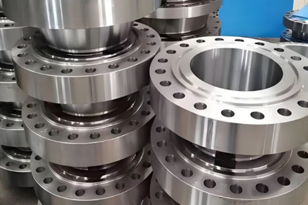
Welded flanges are the foundation of industrial piping. You choose a Slip-On (Plate) flange for low-cost, low-pressure applications, and a Weld Neck flange for high-pressure, high-stress, or critical systems where strength and reliability are non-negotiable.
This is one of the most common decisions an engineer has to make. The choice between these two “basic” flanges sets the tone for the system’s performance and cost. I often explain to customers that while a Slip-On flange might save money initially, the Weld Neck flange is a better long-term investment for any demanding application. Let’s break down exactly why.
Slip-On (SO) or Plate (PL) Flange
The Slip-On flange is the workhorse for low-demand systems. As its name suggests, the pipe literally “slips on” and into the flange center. It is then secured with two fillet welds: one on the outside and one on the inside. This design is simple to manufacture and easy to align during installation. Its main drawback is its lower strength compared to a Weld Neck. The lack of a tapered neck means that stress is concentrated at the welding point, making it unsuitable for high pressures, extreme temperature fluctuations, or high fatigue conditions. We see these used extensively in low-pressure water treatment systems and HVAC circulating lines where the media is non-corrosive and the operating conditions are stable. A chemical plant client of ours in the Philippines successfully switched to PN16 Slip-On flanges for their cooling water system, and it cut their initial investment by 18% and construction time by 30%.
Weld Neck (WN) Flange
The Weld Neck flange is the gold standard for strength and integrity. It features a long, tapered hub or “neck” that is butt-welded directly to the end of the pipe. This design accomplishes two critical things. First, the V-shaped butt weld is as strong as the pipe itself, creating a continuous, high-integrity connection. Second, the tapered neck smoothly transfers stress from the flange to the pipe, dramatically reducing stress concentration at the base. This makes it the ideal choice for high-pressure steam lines, oil and gas pipelines, and any system subject to bending, vibration, or extreme temperatures (both hot and cold).
| Feature | Slip-On (PL) Flange | Weld Neck (WN) Flange |
| Connection | Pipe slips into flange; two fillet welds | Flange neck is butt-welded to pipe |
| Strength | Lower; ~1/3 the fatigue life of WN | High; equal to the pipe itself |
| Pressure Rating | Low to Medium (e.g., up to Class 300) | Full Range (e.g., up to Class 2500) |
| Cost | Lower initial cost (~40% less) | Higher initial cost |
| Best Use Case | Low-pressure water, air, non-critical lines | High-pressure, high-temp, critical systems |
What Makes “Loose-Fit” Flanges a Flexible Solution?
Welding isn’t always practical or even possible, especially with certain pipe materials or in tight spaces. Forcing a traditional flange connection can lead to alignment issues or damage to the pipe itself.
Loose-fit flanges, like Lap Joint and Threaded types, provide clever solutions for systems that need flexibility. They allow for connections without welding the flange directly to the pipe, making installation and maintenance much easier.
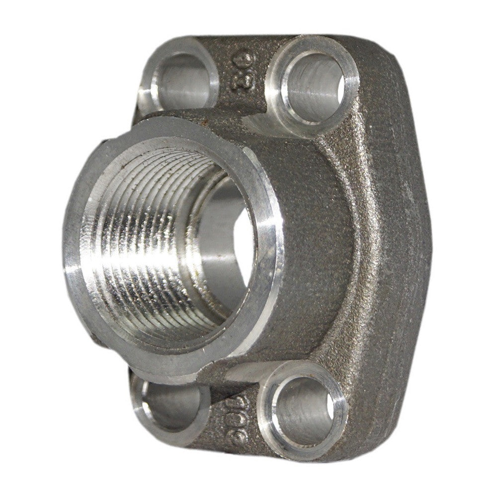
These two flange types solve very different problems, but both are about avoiding a direct weld. This is crucial for buyers working with specialized materials or in environments where “hot work” (welding) is restricted. It’s a perfect example of how the right component choice simplifies a complex installation.
Lap Joint (LJ) Flange
A Lap Joint flange assembly consists of two parts: the flange itself, which looks like a Slip-On flange, and a “stub end,” which is a short piece of pipe with a flared end that is butt-welded to the main pipe. The flange then slips over the stub end and is free to rotate. This design is brilliant for several reasons. First, because the flange itself never touches the process fluid, it can be made from a cheaper material (like carbon steel) while the stub end is made from a more expensive, corrosion-resistant material (like stainless steel). Second, the ability to rotate the flange makes aligning bolt holes incredibly easy, which is a lifesaver in complex piping runs. It’s the go-to solution for non-metallic pipes (PVC, PVDF, fiberglass) or expensive alloy pipes where you want to minimize costs and simplify assembly.
Threaded (TH) Flange
The Threaded flange is the simplest of all: it has internal threads (like NPT or BSPT) that screw directly onto a pipe with matching external threads. Its biggest advantage is speed and simplicity—no welding is required at all. This makes it ideal for small-diameter pipe systems where welding is impractical or in explosive environments where any spark is a hazard. We often supply these for fire protection systems using galvanized steel pipe or for instrument air lines. However, its reliance on threads makes it less suitable for systems with high pressures, high temperatures, or significant vibration, as these forces can cause the threaded connection to leak over time.
Why Choose a Socket Weld Flange for High-Integrity Small Pipes?
You’re working with a small-bore pipe under high pressure. A Slip-On isn’t strong enough, a Threaded flange could leak, and a Weld Neck seems like expensive overkill. You need a better option.
A Socket Weld (SW) flange is the perfect middle ground. It’s a compact, high-strength solution specifically designed for small-diameter piping in high-pressure and high-temperature services, offering a much more reliable connection than a threaded equivalent.
The Socket Weld flange is a smart piece of engineering. It combines the ease of a fillet weld with the structural integrity of a socketed connection. This design provides a smooth flow path and excellent resistance to stress. It’s a detail-oriented choice for applications where leaks are not an option.
Socket Weld (SW) Flange: The Precision Connection
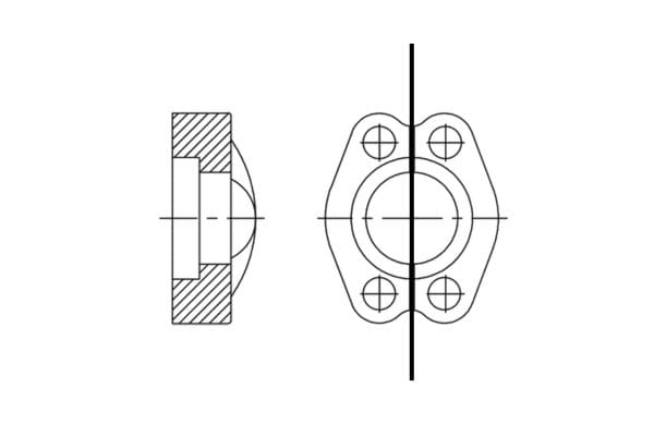
The design of a Socket Weld flange is unique. It has a recessed shoulder, or “socket,” machined into its center. The pipe is inserted into this socket until it bottoms out against the shoulder. It is then backed off slightly (about 1/16″ or 1.5mm) to allow for thermal expansion during welding before a fillet weld is applied around the outside hub. This design creates a very strong, leak-proof connection that is much stronger than a Slip-On flange and twice as strong as a threaded connection. The internal socket also helps ensure a smooth flow path for the fluid, reducing turbulence and erosion. Because of this, SW flanges are the preferred choice for small-bore (typically 3″ and under) process lines in chemical plants and power stations, such as for boiler feedwater or high-temperature steam lines where connection integrity is paramount. Its performance against vibration is also far superior to that of a Slip-On flange.
Are Special-Structure Flanges the Answer for Extreme Conditions?
Your project involves cryogenic temperatures or ultra-high pressures that exceed the limits of any standard flange. Using a conventional part is not just risky; it’s a guarantee of failure.
This is where purpose-built, special-structure flanges are essential. A Long Weld Neck (WNX) flange tackles extreme cold, while an Integral Flange (IF) is forged to handle immense pressure, providing solutions where nothing else can.
Long Weld Neck (WNX) Flange: The Cryogenic Specialist
A Long Weld Neck flange looks like a standard Weld Neck, but its neck is significantly elongated, often 1.5 to 2 times the length. This extended neck serves a critical purpose in cryogenic (ultra-low temperature) applications, such as LNG or liquid nitrogen lines. It moves the actual weld joint away from the extremely cold flange face. This creates a thermal distance piece, protecting the integrity of the weld from the stresses induced by cryogenic temperatures. It also provides the necessary space to apply thick insulation around the pipe without covering the flange bolts, allowing for proper maintenance.
Integral Flange (IF): The Ultimate Strength for High Pressure
An Integral Flange is not a separate part that is welded on; it is forged as a single, continuous piece with the vessel nozzle or pipe section. This completely eliminates the butt weld, which is often the weakest point in an ultra-high-pressure assembly. By forging the flange and body together, you create a component with superior mechanical strength and no risk of weld defects. These are specified for the most extreme pressure applications imaginable, such as the nozzles on nuclear reactor pressure vessels or high-pressure polyethylene reactors, where operating pressures can reach thousands of PSI. These flanges, manufactured under strict standards like ASME BPVC Section VIII, require extensive non-destructive testing (NDT), such as ultrasonic testing (UT), to guarantee there are no internal flaws in the forging. They are the definition of strength and safety.
How Do You Navigate International Flange Standards?
You’re working on a global project. The pump is from the USA, the valves are from Germany, and the pipe is sourced locally in Asia. Nothing fits together. This is a supply chain nightmare.
Understanding the two major international flange standards is the key to global compatibility. ASME/ANSI from the USA and EN/DIN from Europe are the “universal languages” of flange connection, but they are not the same.
ASME B16.5: The North American Standard
The American Society of Mechanical Engineers (ASME) B16.5 is the dominant standard in North America and many other parts of the world influenced by the US oil and gas industry. Its key feature is the pressure rating system, called “Class.” The common classes are 150, 300, 600, 900, 1500, and 2500. A higher class number means the flange can withstand higher pressures at increasing temperatures. This standard specifies dimensions for all flange types, including Weld Neck, Slip-On, Threaded, etc., and defines standard sealing faces like Raised Face (RF), Male-Female (MFM), and Tongue-and-Groove (TG). If you are buying for a project in the Americas or for the oil and gas sector, you are almost certainly working with the ASME standard.
EN 1092-1: The European Standard
The EN 1092-1 standard is the primary specification used throughout the European Union, replacing older national standards like the German DIN. The European system uses a “PN” rating, which stands for Pression Nominale (Nominal Pressure). This number indicates the approximate maximum pressure in bar that the flange can withstand at room temperature. Common ratings are PN6, PN10, PN16, PN25, and PN40. While a PN rating can sometimes be roughly correlated to an ASME Class (e.g., Class 150 is similar to PN20), they are **not interchangeable**. An EN flange will have different dimensions—such as thickness, bolt circle diameter, or number of bolts—than an ASME flange of a similar pressure class. We worked on one multinational chemical project where specifying ASME B16.5 for all equipment from the start was the crucial decision that allowed machinery from China, the USA, and Europe to be connected seamlessly on-site.
What Are the Go-To Flanges for Specialized Industries?
A standard flange won’t work. Your application in food processing requires perfect hygiene, your oil tank needs a high-integrity seal, or you simply need to connect two different pipe sizes together.
This is where application-specific and custom flanges come in. Sanitary flanges for clean industries, API 6A flanges for oil and gas, and Reducing flanges for changing pipe diameters are all tailored solutions for unique problems.
These flanges show how versatile this simple component can be. The fundamental design is adapted to solve very specific challenges. For us as a supplier, offering standard, custom, and specialty products is what enables true one-stop sourcing for detail-oriented buyers across all industries.
Sanitary Flanges (e.g., DIN 11851): The Clean Connection
In the food, beverage, and pharmaceutical industries, cleanliness is everything. A standard industrial flange has crevices and rough surfaces where bacteria can grow. Sanitary flanges, often called “Tri-Clamp” or hygienic flanges, are designed to eliminate this risk. They are made from high-grade stainless steel (like 316L) and polished to a very smooth surface finish (Ra ≤ 0.8μm) with no dead corners. Instead of bolts, they use a quick-release clamp that compresses a gasket (usually silicone or EPDM) between two flange faces, creating a smooth, hygienic, and easily disassembled joint for cleaning-in-place (CIP) systems.
API 6A Flanges: The Oil & Gas Seal Expert
The American Petroleum Institute (API) 6A standard governs equipment for wellhead and Christmas tree applications in oil and gas. These flanges are built for extremely high pressures (from 2,000 to 20,000 psi) and demanding service. Their key feature is the use of a Ring Type Joint (RTJ) sealing face. Instead of a flat gasket, they use a solid metal ring (often octagonal in shape) that sits in a specially machined groove. When the bolts are tightened, the soft metal ring deforms and creates an intense metal-to-metal seal that is far more robust and reliable under immense pressure and temperature than any soft gasket. These are the mandatory choice for high-pressure storage tanks, offshore platforms, and anywhere a leak could be catastrophic.
Reducing Flanges: The Simple Transition
A reducing flange is a straightforward solution for a common problem: connecting a larger pipe to a smaller pipe. It is essentially a flange with one specified diameter but a smaller bore. This saves space and reduces cost by eliminating the need for a separate reducer fitting and a standard flange. They can be concentric (where the bore is centered) for vertical pipe runs, or eccentric (where the bore is offset) for horizontal runs. The eccentric design, with the flat side typically at the bottom (“Bottom Flat”), prevents an accumulation of fluid or air at the transition point. When ordering, it’s critical to specify both the main flange size and the smaller bore size (e.g., DN300 to DN200), and for eccentric types, the direction of the offset.
Conclusion
Flange selection is a crucial engineering decision driven by pressure, temperature, media, and application. Mastering these 12 types ensures a safe, efficient, and long-lasting industrial piping system. If you need high quality hydraulic flanges, contact Topa and we’ll arrange them for you!


