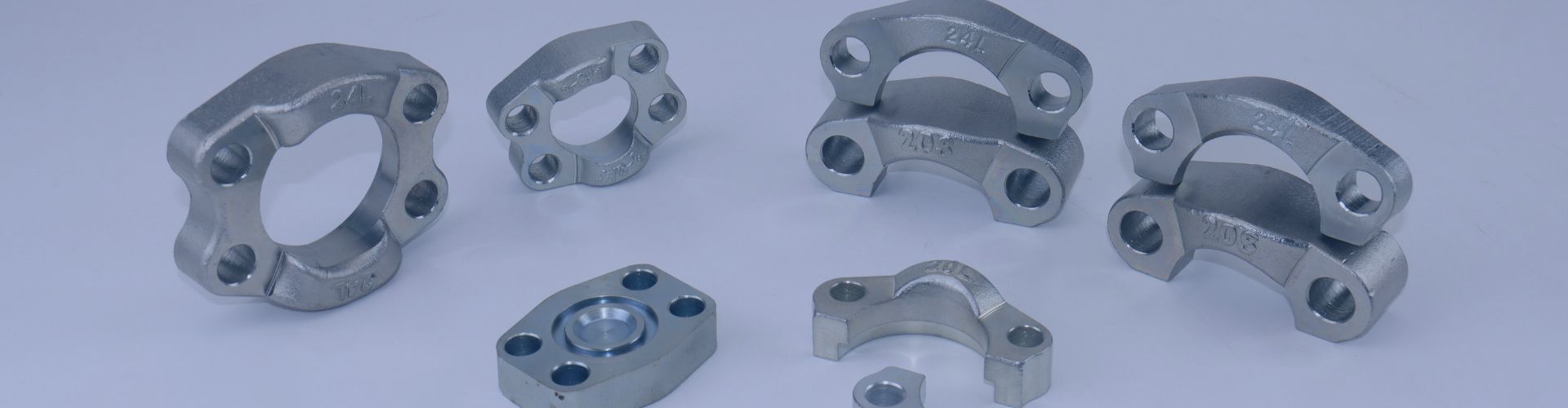
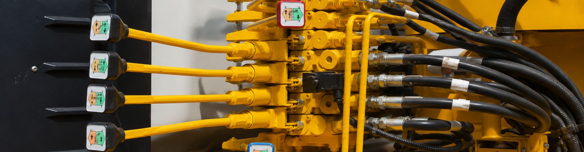
How Do You Choose the Right Flange for Your Piping System

How Do You Choose the Right Flange for Your Piping System?

You select a flange that seems to fit, but a persistent leak leads to costly downtime and safety risks. Over 35% of industrial piping failures stem from incorrect flange selection.

The right flange is not just a connector; it’s a critical component engineered for specific pressures, temperatures, and media. Choosing correctly, from a simple Slip-On to a high-pressure Weld Neck, is essential for system integrity, longevity, and safety, potentially extending system life by 2-3 times.

DIN Hydraulic Flange Standards

When Should You Use a Rigid, Welded Flange?

You need a strong, permanent connection, but the choice between weld types is confusing. Picking the wrong one can create a weak point that fails under pressure, compromising your entire system.

Welded flanges are the foundation of industrial piping. You choose a Slip-On (Plate) flange for low-cost, low-pressure applications, and a Weld Neck flange for high-pressure, high-stress, or critical systems where strength and reliability are non-negotiable.

cut split hydralic flange Topa

This is one of the most common decisions an engineer has to make. The choice between these two “basic” flanges sets the tone for the system’s performance and cost. I often explain to customers that while a Slip-On flange might save money initially, the Weld Neck flange is a better long-term investment for any demanding application. Let’s break down exactly why.

Slip-On (SO) or Plate (PL) Flange

The Slip-On flange is the workhorse for low-demand systems. As its name suggests, the pipe literally “slips on” and into the flange center. It is then secured with two fillet welds: one on the outside and one on the inside. This design is simple to manufacture and easy to align during installation. Its main drawback is its lower strength compared to a Weld Neck. The lack of a tapered neck means that stress is concentrated at the welding point, making it unsuitable for high pressures, extreme temperature fluctuations, or high fatigue conditions. We see these used extensively in low-pressure water treatment systems and HVAC circulating lines where the media is non-corrosive and the operating conditions are stable. A chemical plant client of ours in the Philippines successfully switched to PN16 Slip-On flanges for their cooling water system, and it cut their initial investment by 18% and construction time by 30%.

Weld Neck (WN) Flange

The Weld Neck flange is the gold standard for strength and integrity. It features a long, tapered hub or “neck” that is butt-welded directly to the end of the pipe. This design accomplishes two critical things. First, the V-shaped butt weld is as strong as the pipe itself, creating a continuous, high-integrity connection. Second, the tapered neck smoothly transfers stress from the flange to the pipe, dramatically reducing stress concentration at the base. This makes it the ideal choice for high-pressure steam lines, oil and gas pipelines, and any system subject to bending, vibration, or extreme temperatures (both hot and cold).

What Makes “Loose-Fit” Flanges a Flexible Solution?

Welding isn’t always practical or even possible, especially with certain pipe materials or in tight spaces. Forcing a traditional flange connection can lead to alignment issues or damage to the pipe itself.

Loose-fit flanges, like Lap Joint and Threaded types, provide clever solutions for systems that need flexibility. They allow for connections without welding the flange directly to the pipe, making installation and maintenance much easier.

NPT SAE Flange

These two flange types solve very different problems, but both are about avoiding a direct weld. This is crucial for buyers working with specialized materials or in environments where “hot work” (welding) is restricted. It’s a perfect example of how the right component choice simplifies a complex installation.

Lap Joint (LJ) Flange

A Lap Joint flange assembly consists of two parts: the flange itself, which looks like a Slip-On flange, and a “stub end,” which is a short piece of pipe with a flared end that is butt-welded to the main pipe. The flange then slips over the stub end and is free to rotate. This design is brilliant for several reasons. First, because the flange itself never touches the process fluid, it can be made from a cheaper material (like carbon steel) while the stub end is made from a more expensive, corrosion-resistant material (like stainless steel). Second, the ability to rotate the flange makes aligning bolt holes incredibly easy, which is a lifesaver in complex piping runs. It’s the go-to solution for non-metallic pipes (PVC, PVDF, fiberglass) or expensive alloy pipes where you want to minimize costs and simplify assembly.

Threaded (TH) Flange

The Threaded flange is the simplest of all: it has internal threads (like NPT or BSPT) that screw directly onto a pipe with matching external threads. Its biggest advantage is speed and simplicity—no welding is required at all. This makes it ideal for small-diameter pipe systems where welding is impractical or in explosive environments where any spark is a hazard. We often supply these for fire protection systems using galvanized steel pipe or for instrument air lines. However, its reliance on threads makes it less suitable for systems with high pressures, high temperatures, or significant vibration, as these forces can cause the threaded connection to leak over time.

Why Choose a Socket Weld Flange for High-Integrity Small Pipes?

You’re working with a small-bore pipe under high pressure. A Slip-On isn’t strong enough, a Threaded flange could leak, and a Weld Neck seems like expensive overkill. You need a better option.

A Socket Weld (SW) flange is the perfect middle ground. It’s a compact, high-strength solution specifically designed for small-diameter piping in high-pressure and high-temperature services, offering a much more reliable connection than a threaded equivalent.

The Socket Weld flange is a smart piece of engineering. It combines the ease of a fillet weld with the structural integrity of a socketed connection. This design provides a smooth flow path and excellent resistance to stress. It’s a detail-oriented choice for applications where leaks are not an option.

Socket Weld (SW) Flange: The Precision Connection

The design of a Socket Weld flange is unique. It has a recessed shoulder, or “socket,” machined into its center. The pipe is inserted into this socket until it bottoms out against the shoulder. It is then backed off slightly (about 1/16″ or 1.5mm) to allow for thermal expansion during welding before a fillet weld is applied around the outside hub. This design creates a very strong, leak-proof connection that is much stronger than a Slip-On flange and twice as strong as a threaded connection. The internal socket also helps ensure a smooth flow path for the fluid, reducing turbulence and erosion. Because of this, SW flanges are the preferred choice for small-bore (typically 3″ and under) process lines in chemical plants and power stations, such as for boiler feedwater or high-temperature steam lines where connection integrity is paramount. Its performance against vibration is also far superior to that of a Slip-On flange.

Are Special-Structure Flanges the Answer for Extreme Conditions?

Your project involves cryogenic temperatures or ultra-high pressures that exceed the limits of any standard flange. Using a conventional part is not just risky; it’s a guarantee of failure.

This is where purpose-built, special-structure flanges are essential. A Long Weld Neck (WNX) flange tackles extreme cold, while an Integral Flange (IF) is forged to handle immense pressure, providing solutions where nothing else can.

Long Weld Neck (WNX) Flange: The Cryogenic Specialist

A Long Weld Neck flange looks like a standard Weld Neck, but its neck is significantly elongated, often 1.5 to 2 times the length. This extended neck serves a critical purpose in cryogenic (ultra-low temperature) applications, such as LNG or liquid nitrogen lines. It moves the actual weld joint away from the extremely cold flange face. This creates a thermal distance piece, protecting the integrity of the weld from the stresses induced by cryogenic temperatures. It also provides the necessary space to apply thick insulation around the pipe without covering the flange bolts, allowing for proper maintenance.

Integral Flange (IF): The Ultimate Strength for High Pressure

An Integral Flange is not a separate part that is welded on; it is forged as a single, continuous piece with the vessel nozzle or pipe section. This completely eliminates the butt weld, which is often the weakest point in an ultra-high-pressure assembly. By forging the flange and body together, you create a component with superior mechanical strength and no risk of weld defects. These are specified for the most extreme pressure applications imaginable, such as the nozzles on nuclear reactor pressure vessels or high-pressure polyethylene reactors, where operating pressures can reach thousands of PSI. These flanges, manufactured under strict standards like ASME BPVC Section VIII, require extensive non-destructive testing (NDT), such as ultrasonic testing (UT), to guarantee there are no internal flaws in the forging. They are the definition of strength and safety.

How Do You Navigate International Flange Standards?

You’re working on a global project. The pump is from the USA, the valves are from Germany, and the pipe is sourced locally in Asia. Nothing fits together. This is a supply chain nightmare.

Understanding the two major international flange standards is the key to global compatibility. ASME/ANSI from the USA and EN/DIN from Europe are the “universal languages” of flange connection, but they are not the same.

Hydraulic Flange Standards

ASME B16.5: The North American Standard

The American Society of Mechanical Engineers (ASME) B16.5 is the dominant standard in North America and many other parts of the world influenced by the US oil and gas industry. Its key feature is the pressure rating system, called “Class.” The common classes are 150, 300, 600, 900, 1500, and 2500. A higher class number means the flange can withstand higher pressures at increasing temperatures. This standard specifies dimensions for all flange types, including Weld Neck, Slip-On, Threaded, etc., and defines standard sealing faces like Raised Face (RF), Male-Female (MFM), and Tongue-and-Groove (TG). If you are buying for a project in the Americas or for the oil and gas sector, you are almost certainly working with the ASME standard.

EN 1092-1: The European Standard

The EN 1092-1 standard is the primary specification used throughout the European Union, replacing older national standards like the German DIN. The European system uses a “PN” rating, which stands for Pression Nominale (Nominal Pressure). This number indicates the approximate maximum pressure in bar that the flange can withstand at room temperature. Common ratings are PN6, PN10, PN16, PN25, and PN40. While a PN rating can sometimes be roughly correlated to an ASME Class (e.g., Class 150 is similar to PN20), they are **not interchangeable**. An EN flange will have different dimensions—such as thickness, bolt circle diameter, or number of bolts—than an ASME flange of a similar pressure class. We worked on one multinational chemical project where specifying ASME B16.5 for all equipment from the start was the crucial decision that allowed machinery from China, the USA, and Europe to be connected seamlessly on-site.

What Are the Go-To Flanges for Specialized Industries?

A standard flange won’t work. Your application in food processing requires perfect hygiene, your oil tank needs a high-integrity seal, or you simply need to connect two different pipe sizes together.

This is where application-specific and custom flanges come in. Sanitary flanges for clean industries, API 6A flanges for oil and gas, and Reducing flanges for changing pipe diameters are all tailored solutions for unique problems.

These flanges show how versatile this simple component can be. The fundamental design is adapted to solve very specific challenges. For us as a supplier, offering standard, custom, and specialty products is what enables true one-stop sourcing for detail-oriented buyers across all industries.

Sanitary Flanges (e.g., DIN 11851): The Clean Connection

In the food, beverage, and pharmaceutical industries, cleanliness is everything. A standard industrial flange has crevices and rough surfaces where bacteria can grow. Sanitary flanges, often called “Tri-Clamp” or hygienic flanges, are designed to eliminate this risk. They are made from high-grade stainless steel (like 316L) and polished to a very smooth surface finish (Ra ≤ 0.8μm) with no dead corners. Instead of bolts, they use a quick-release clamp that compresses a gasket (usually silicone or EPDM) between two flange faces, creating a smooth, hygienic, and easily disassembled joint for cleaning-in-place (CIP) systems.

API 6A Flanges: The Oil & Gas Seal Expert

The American Petroleum Institute (API) 6A standard governs equipment for wellhead and Christmas tree applications in oil and gas. These flanges are built for extremely high pressures (from 2,000 to 20,000 psi) and demanding service. Their key feature is the use of a Ring Type Joint (RTJ) sealing face. Instead of a flat gasket, they use a solid metal ring (often octagonal in shape) that sits in a specially machined groove. When the bolts are tightened, the soft metal ring deforms and creates an intense metal-to-metal seal that is far more robust and reliable under immense pressure and temperature than any soft gasket. These are the mandatory choice for high-pressure storage tanks, offshore platforms, and anywhere a leak could be catastrophic.

Reducing Flanges: The Simple Transition

A reducing flange is a straightforward solution for a common problem: connecting a larger pipe to a smaller pipe. It is essentially a flange with one specified diameter but a smaller bore. This saves space and reduces cost by eliminating the need for a separate reducer fitting and a standard flange. They can be concentric (where the bore is centered) for vertical pipe runs, or eccentric (where the bore is offset) for horizontal runs. The eccentric design, with the flat side typically at the bottom (“Bottom Flat”), prevents an accumulation of fluid or air at the transition point. When ordering, it’s critical to specify both the main flange size and the smaller bore size (e.g., DN300 to DN200), and for eccentric types, the direction of the offset.

Conclusion

Flange selection is a crucial engineering decision driven by pressure, temperature, media, and application. Mastering these 12 types ensures a safe, efficient, and long-lasting industrial piping system. If you need high quality hydraulic flanges, contact Topa and we’ll arrange them for you!

Hydraulic Flange Installation banner

Hydraulic Flange Installation: Torque Specs & Best Practices

Proper hydraulic flange installation is critical for maintaining the safety, reliability, and performance of your hydraulic system. Even small installation errors can lead to leaks, decreased efficiency, or severe system failures. By ensuring correct alignment, following accurate torque specifications, and using recommended flange assembly procedures, you can significantly enhance equipment longevity, prevent costly downtime, and safeguard workers from potential hazards. Ultimately, mastering the best practices for hydraulic flange installation is key to running a robust, leak-free, and efficient hydraulic system.

Understanding Hydraulic Flange Fittings

What Are Hydraulic Flange Fittings?

Hydraulic flange fittings are specialized connectors designed for joining tubes, hoses, and pipes in high-pressure hydraulic systems. Unlike traditional threaded fittings, these flanges use bolts and flat surfaces for sealing, creating connections that can reliably withstand extreme pressure and vibration. Typically consisting of a flange head, gasket (usually an O-ring), bolts, and clamp halves, these fittings provide robust sealing solutions that ensure leak-proof, secure connections. Hydraulic flange fittings are favored in various industries because they simplify assembly, facilitate easy maintenance, and offer enhanced sealing capabilities compared to traditional fittings.

split Hydraulic Flange Installation

SAE J518 Standard: Code 61 vs. Code 62 Flanges

When dealing with hydraulic flange fittings, it’s crucial to understand the SAE J518 standard, which classifies flanges into two primary types: Code 61 and Code 62.

Code 61 Flanges are designed for applications with pressure ratings up to approximately 3000–5000 PSI. They have a lighter-duty bolt pattern and thinner flange thickness, suitable for moderate hydraulic pressures and general industrial equipment.

Code 62 Flanges, in contrast, are intended for more demanding high-pressure applications, accommodating pressures up to 6000 PSI. They feature heavier, more robust construction with a thicker flange and a bolt pattern designed to withstand significantly greater stresses and pressures.

It’s vital to note that despite visual similarities, Code 61 and Code 62 flanges are not interchangeable due to their differing bolt patterns, dimensions, and sealing requirements. Incorrectly interchanging them can lead to leaks, premature failure, or even safety hazards.

Applications: From High-Pressure Flanges to Hydraulic Hose Fittings

Hydraulic flange fittings are widely utilized across numerous industries, particularly in environments requiring high-pressure performance and vibration resistance. Typical applications include construction equipment, heavy machinery, mining operations, industrial hydraulic presses, agricultural machinery, oil and gas installations, and marine systems.

In hydraulic systems requiring high-pressure flanges, such as heavy-duty earthmoving machinery or drilling equipment, Code 62 flanges are preferred due to their enhanced strength and sealing capabilities. Conversely, Code 61 flanges are suitable for less extreme applications, like industrial hydraulic power units and moderate-pressure mobile equipment.

Additionally, hydraulic flange fittings are commonly paired with hydraulic hoses, offering secure and robust connections that can be easily serviced and maintained. They play a critical role in ensuring system integrity, reducing maintenance downtime, and improving overall reliability.

Essential Tools & Equipment for Hydraulic Flange Installation

Torque Wrench Settings: Ensuring Accuracy

Accurate torque wrench settings are the cornerstone of successful hydraulic flange installations. A torque wrench precisely measures the amount of force applied when tightening bolts, ensuring each bolt meets the manufacturer’s exact torque specifications. Using the correct torque wrench settings helps you achieve optimal sealing without risking damage to the flange or bolts. Improper torque can lead to overtightening, causing distortion, stress fractures, or under-tightening, which results in leaks or even bolt loosening during operation. To achieve consistent and reliable results, always follow the recommended torque specifications outlined in the flange torque chart provided by the manufacturer or the SAE J518 standard.

Importance of Torque Calibration and Verification

Regular calibration and verification of your torque wrench are essential yet frequently overlooked aspects of hydraulic flange installation. Even minor inaccuracies in your torque wrench can lead to substantial deviations in bolt tightness, significantly affecting flange performance and system reliability. Calibration ensures your torque wrench accurately applies the specified torque, safeguarding flange joints against potential leaks and failures. Regular verification, ideally at scheduled intervals or before critical installations, guarantees consistent accuracy and dependable outcomes. By prioritizing torque wrench accuracy, you’ll protect the integrity of your hydraulic connections, improve operational safety, and minimize maintenance costs over the long term.

Selecting the Right Bolts: ISO 616 Bolts & Beyond

Choosing the right bolts for your hydraulic flange installation is just as critical as using proper torque settings. ISO 616 bolts, widely recognized in hydraulic systems, are specially designed to provide superior strength, corrosion resistance, and reliability under high-pressure and vibration conditions. Selecting bolts compliant with ISO 616 standards or equivalent ensures compatibility, optimal load distribution, and lasting integrity of the flange connection. Beyond standardization, it’s crucial to match bolt length, material strength, and thread lubrication to your specific application. Proper bolt selection combined with accurate torque settings reduces the risk of mechanical failure, leakage, and costly downtime. Always refer to industry guidelines, flange specifications, and torque tables to choose bolts that meet your system’s exact requirements and operating environment.

Step-by-Step Flange Assembly Procedure

Preparing Flange Surfaces: Ensuring Proper Flange Alignment

Hydraulic Flange Installation steps

Gasket Installation: O-Ring Flanges and Flange Sealing Methods

Thread Lubrication: Small Detail, Big Difference

Bolt Torque Sequence & Tightening Patterns

Understanding Tightening Torque Specifications

Accurately understanding tightening torque specifications is essential to creating secure, leak-proof hydraulic flange installations. Torque specifications indicate the precise amount of rotational force required to tighten bolts, ensuring optimal flange sealing without risking damage. These specifications vary depending on flange type, bolt size, and the material involved. Adhering strictly to these guidelines helps prevent uneven bolt loads, flange distortion, and potential leaks or failures under pressure. Always consult the manufacturer’s specifications or SAE J518 standards to ensure you’re applying the correct torque settings.

Torque Table Guide: Quick Reference for Code 61 & Code 62 Flanges

Having a clear and accessible torque table simplifies your hydraulic flange installation, especially when dealing with Code 61 and Code 62 flanges. Here’s a quick-reference guide based on common flange sizes:

Code 61 (3000–5000 PSI):

Code 62 (6000 PSI):

Keep this torque table handy during installations to quickly verify torque values and streamline your flange assembly process.

Tightening Cross Pattern: Ensuring Uniform Pressure

The tightening cross pattern is essential for evenly distributing bolt pressure across the flange surfaces. Applying torque in a cross or diagonal sequence ensures the flange surfaces compress evenly, significantly reducing the risk of leaks, flange distortion, or gasket damage. Follow these steps:

Consistently using this tightening pattern guarantees balanced pressure, enhances sealing performance, and ensures long-term flange reliability.

Preventing Hydraulic Connection Leaks & Failures

Leakage Prevention: Hydraulic Sealing Technology Explained

Hydraulic sealing technology plays a crucial role in preventing leaks within hydraulic flange connections. Effective sealing solutions typically rely on precision-engineered components, such as O-ring gaskets, which are specifically designed to withstand high pressures and dynamic operating conditions. Here’s how you can maximize sealing effectiveness:

Ensuring Vibration Resistance and Durability

Hydraulic systems often operate in high-vibration environments, which can weaken connections over time. To enhance flange durability and resist vibration-induced failures:

Hydraulic Flange Installation tools

Flange Inspection Techniques: Spotting Issues Early

Proactive inspection is your best defense against leaks and hydraulic failures. Regular flange inspections enable early detection and swift correction of potential issues:

By consistently applying these flange inspection techniques, you’ll maintain reliable hydraulic connections, extend equipment lifespan, and significantly reduce downtime.

Troubleshooting Common Hydraulic Flange Issues

Diagnosing and Correcting Flange Alignment Problems

Flange misalignment is a frequent issue causing leaks and system inefficiencies. Identifying alignment problems early and correcting them effectively is critical:

Addressing Bolted Joint Assembly Failures

Failures in bolted flange joints can lead to serious hydraulic leaks or operational hazards. Here’s how to diagnose and resolve these issues quickly:

Quick Fixes vs. Professional Solutions: Making the Right Call

Deciding whether to apply quick fixes or seek professional assistance is essential for effective troubleshooting:

Knowing when to choose immediate corrective actions or invest in professional servicing can save significant downtime and costs, ensuring long-term reliability and safety for your hydraulic system.

Conclusion

Remember, investing in accurate tools, following recommended torque practices, and staying vigilant about routine inspections isn’t merely beneficial—it’s essential. Adopting these best practices ensures your hydraulic flange installations remain robust and dependable under pressure, ultimately contributing to a safer and more productive workplace.

If you need high quality hydraulic flanges, welcome to contact Topa, we can provide the highest quality products!


FAQ

What is the difference between Code 61 and Code 62 flanges?

Code 61 flanges handle lower pressures (up to around 3000–5000 PSI), while Code 62 flanges are designed for high-pressure applications (up to 6000 PSI).

How often should I check the torque on hydraulic flange bolts?

It’s best to verify bolt torque after initial installation, after the first operational cycle, and periodically (every 6–12 months) thereafter.

Why is thread lubrication important in flange installations?

Lubrication reduces friction, ensures accurate torque application, prevents thread galling, and helps maintain consistent bolt tightness.

Can improper flange alignment cause leaks?

Yes, even slight misalignment can lead to uneven gasket pressure, resulting in leaks and eventual system failures.

What are common signs of flange installation errors?

Visible leaks, loose bolts, uneven flange gaps, vibration issues, and premature gasket wear are typical signs of installation problems.

Can I reuse flange bolts and gaskets?

It’s not recommended—always use new gaskets and inspect bolts thoroughly. Replace bolts that show signs of damage, corrosion, or thread wear.

Hydraulic Flange Standards Banner

Hydraulic Flange Standards: Key Global Variations

Imagine installing a brand-new hydraulic system—only to realize the flanges don’t align. Bolts won’t fit, pressure ratings mismatch, and now your project is delayed for weeks. Sound familiar? That’s the risk of mixing incompatible flange standards. Every flange standard dictates critical details like size, pressure capacity, and bolt pattern. Get it wrong, and you’re facing leaks, system failures, or costly rework. Whether you’re working on heavy machinery in the U.S. or exporting equipment to Europe, understanding which hydraulic flange standard to follow isn’t optional—it’s the key to a reliable, headache-free connection. So, which standards should you trust? Let’s break it down.

What Are Hydraulic Flange Standards?

Hydraulic flange standards are the rulebooks that define how flanges should be designed, measured, and manufactured to ensure a perfect, pressure-tight connection in fluid power systems. They exist to make sure parts from different manufacturers can fit together seamlessly, reducing guesswork, errors, and compatibility issues during installation.

These standards cover everything from flange dimensions (inner and outer diameters, bolt circle, thickness) to tolerances, pressure ratings, bolt hole layout, and seal surface configurations. Whether you’re using slip-on, weld-neck, or socket-weld types, the flange’s exact design must match the standard you’re working with.

In hydraulic systems, flanges act as mission-critical connection points between pipes, hoses, pumps, and valves. They’re often used in high-pressure applications, where leakage or misalignment can result in serious safety risks, downtime, or mechanical damage. A properly standardized flange ensures reliable performance, easier maintenance, and global interchangeability—especially in systems that operate under extreme pressure and vibration.

Hydraulic Flange Standards

The Big Four: Most Widely Used Flange Standards

When it comes to hydraulic systems, flange compatibility isn’t just a detail—it’s everything. Let’s look at the four most common hydraulic flange standards used around the world, how they differ, and why choosing the right one matters.

SAE J518 (Code 61 / Code 62)

SAE J518 is a U.S.-based standard specifically designed for high-pressure hydraulic systems. You’ll find it everywhere—from construction machinery to oil rigs. It comes in two pressure ratings:

Both types use inch-based measurements and share similar bolt hole patterns, but they’re not interchangeable due to differences in flange thickness and pressure capabilities.

Typical use cases include agricultural equipment, mobile hydraulics, and mining operations—anywhere durability and leak-proof connections are non-negotiable.

ISO 6162

ISO 6162 is the international counterpart to SAE J518, using metric dimensions but based on the same design principles.

While the two standards appear nearly identical, don’t assume they’re fully interchangeable—minor dimensional differences can cause seal issues. If your components are sourced internationally, double-check you’re matching ISO with ISO—not mixing with SAE unless you’re using compatible adapters.

ANSI / ASME B16.5

This is the go-to flange standard in the U.S. for general industrial use—not limited to hydraulics. It covers a wide range of applications, including oil & gas, chemical processing, and power generation.

Its strength is versatility, but its major downside? It’s completely incompatible with European DIN flanges, despite some visual similarities.

EN 1092 / DIN

This European standard is built for metric-based hydraulic and industrial systems. It’s widely used in Europe, Asia, and international maritime systems. DIN flanges are often required when you’re working on ships, European factories, or global equipment brands.

Major Differences Between American and European Flanges

When someone says, “A flange is a flange,” they’ve clearly never tried matching an ANSI flange to a DIN one. At first glance, American and European flanges might seem similar—but the devil’s in the details. Let’s break down where these standards truly part ways.

Unit of Measurement: Inches vs Millimeters

American standards like ANSI/ASME B16.5 use inches for all dimensions—diameter, bolt spacing, thickness, everything. On the other hand, European standards such as EN 1092-1 / DIN follow the metric system, measuring in millimeters.

This alone makes them tricky to swap. A flange marked 6 inches isn’t the same as DN150—even if they look roughly the same size.

Pressure Ratings: Class vs PN

ANSI flanges rate pressure with Class numbers—like Class 150, 300, 600, all the way up to 2500. These numbers are tied to PSI ratings and vary with temperature.

DIN/EN flanges, however, use PN (Pressure Nominale) values—like PN10, PN16, or PN40—which are pressure ratings measured in bar, typically at ambient temperature.

So even if the physical size matches, a Class 300 flange isn’t automatically equal to a PN40. Mismatching pressure specs can lead to serious system failures.

Bolt Pattern, Thickness & Sealing Face Design

This is where it gets messier.

These subtle differences make them mechanically incompatible—even if you manage to get the bolts through.

Regional Engineering Preferences

So if you’re exporting or sourcing globally, knowing your destination’s preferred standard is just as important as knowing the specs.

Why They’re Not Interchangeable

To put it simply: just because two flanges have similar diameters doesn’t mean they fit the same system. Pressure mismatches, sealing issues, and even minor misalignment can lead to leaks, blowouts, or permanent damage.

Bottom line? ANSI and DIN are two different languages, and trying to “translate” between them without adapters or proper redesign usually leads to expensive mistakes.

Compatibility Issues: Why Mixing Standards Is Risky

Mixing hydraulic flange standards might seem like a clever shortcut—especially when you’re in a pinch and the parts look “close enough.” But here’s the harsh truth: in hydraulics, close doesn’t cut it. When you’re dealing with high-pressure systems, even tiny differences in dimensions can spell disaster.

Whether it’s a mismatch in bolt hole layout, a slight variance in flange thickness, or a seal face that doesn’t quite align, the result is the same: leaks, mechanical failures, or catastrophic blowouts. And by the time those issues surface, the damage is already done.

Bolt Misalignment and Sealing Failures

Let’s get specific. Imagine you’ve got an ANSI Class 300 flange, and you’re trying to mate it with a DIN PN40 flange. At a glance, the bolt holes seem to be in the right spot. You grab your wrench and get to work.

But what you don’t see is that the bolt circle diameter (BCD) is slightly off. The holes are a few millimeters too tight, or the thickness of the flanges causes your gaskets to misseat. The sealing face types might also differ—raised face (RF) on the ANSI side vs. a flat face (FF) on the DIN side. These variations may not be visible to the naked eye, but they matter—a lot.

You manage to tighten everything down. No leaks. System starts. Looks like a win… until two weeks later, under full load, a slow drip appears. That drip becomes a leak. Then, under pressure, it blows—releasing high-pressure hydraulic fluid and shutting the system down.

This kind of failure is 100% avoidable—but only if you recognize that standards aren’t suggestions.

DIN Hydraulic Flange Standards

Real-World Scenario: The “Forced Fit” Disaster

A marine contractor once tried to retrofit a U.S.-built hydraulic pump onto a European-manufactured ship system. The pump flange followed ANSI Class 600, while the ship’s piping was built to EN 1092 PN40 specs. Instead of sourcing the correct adapter, they took matters into their own hands.

They redrilled the flange holes manually and “forced” the connection into place. It seemed to work at first—until sea trials began.

Just an hour into operation, the flange started leaking. Under pressure, the mismatch caused the seal to shear, resulting in a significant spill. Not only did the ship fail its inspection, but the repair involved dry-docking the vessel, replacing both flange sets, and re-certifying the system.

Total cost: $15,000 in parts and labor, plus three days of lost time. That’s a massive price to pay for trying to skip over standards.

What About Adapters?

Okay, but what if you’re stuck between two systems—say, an American pump and European piping? Are you out of luck?

Not quite. Adapters and transition flanges can bridge the gap—but only if they’re properly designed.

Here’s what a reliable adapter must do:

But let’s be clear—adapters add cost, increase complexity, and introduce extra failure points. If they’re not properly engineered, they can end up being the weakest part of your system.

If you’re designing a new hydraulic setup or even expanding an existing one, it’s almost always smarter to standardize from the start. Pick one system—SAE, DIN, ISO, or ANSI—and make sure every fitting, flange, and gasket lines up with it. Your future self will thank you.

How to Choose the Right Hydraulic Flange Standard

Choosing the right flange standard isn’t just about ticking boxes on a spec sheet—it’s about preventing future problems, ensuring system integrity, and saving time and money down the road. Here’s how to make the right call, step by step.

Step 1: Where Is the Project Located?

The first question to ask is: Where will this system operate?

Local standards are more likely to be supported by contractors, inspectors, and regional suppliers. That means faster sourcing and fewer headaches during installation.

Step 2: What’s the Pressure Requirement?

This is where things get real. If you’re working with high-pressure hydraulic applications, your flange needs to match the load.

If you’re running a 4000+ PSI system and try to cut corners with PN16 parts, you’re risking a blowout. Match the pressure, not just the size.

Step 3: Is the System Already Using a Standard?

Don’t mix standards.

If you’re connecting to an existing system, stick with the flange standard that’s already in use—whether that’s DIN, SAE, or ANSI. Swapping one part often leads to a domino effect of incompatibility, and you’ll end up needing adapters or reworking everything.

Step 4: What’s Available Through Your Supply Chain?

Let’s be practical. Even if you want ISO flanges, if your local supplier only stocks ANSI, you’re going to face lead times and cost issues.

Ask yourself:

Sometimes, availability drives the decision—just don’t compromise on safety or compatibility.

Final Tip: Match the Application, Not Just the Location

While geography and supply are important, the working conditions should lead to the decision. Here’s a simple priority guide:

Choose the standard that can handle your workload safely, integrate with your current setup seamlessly, and be supported reliably over the long term.

Final Conclusion

In high-pressure hydraulic systems, flange standards aren’t just technical details—they’re the backbone of safe, reliable performance. Whether you’re building a new system or maintaining an existing one, using the correct standard—SAE, ISO, ANSI, or DIN—ensures compatibility, prevents costly failures, and keeps operations running smoothly. Mixing flanges may seem convenient, but it often leads to leaks, downtime, and unexpected expenses.

Need hydraulic flanges that meet global standards and ship fast? Topa offers a full range of SAE, ISO, DIN, and ANSI flanges—precision-machined, pressure-tested, and ready to go. Contact us today to get expert support and high-quality products that fit right the first time.


FAQ

Can I use a DIN flange with an ANSI flange?

No, they are not compatible due to differences in dimensions, bolt patterns, and sealing faces.

What does “PN” mean in DIN flange standards?

PN stands for “Pressure Nominale” and indicates the pressure rating in bar (e.g., PN16 = 16 bar).

What is the difference between SAE Code 61 and Code 62?

Code 61 is rated for 3000 PSI, while Code 62 is for higher-pressure systems up to 6000 PSI.

Are ISO 6162 flanges the same as SAE flanges?

They are very similar. ISO 6162-1 matches SAE Code 61, and ISO 6162-2 matches Code 62, but dimensions may vary slightly.

Can I mix flange standards using an adapter?

Yes, but only if the adapter is professionally engineered and pressure-rated for both standards.

Which flange standard is best for high-pressure systems?

SAE Code 62 and ISO 6162-2 are ideal for systems up to 6000 PSI.

threaded vs socket weld flanges banner

Threaded vs Socket Weld Flanges: Which Offers a Better Seal?

Flanges allow sections of a system to be joined or separated easily, simplifying everything from installation to inspection and routine maintenance. However, not all flanges are created equal. Choosing the wrong type for your application can lead to inefficiencies, unexpected leaks, or even system failure. In this article, we’ll focus on two common flange types: threaded flanges and socket weld flanges. Let’s break down how they work, where they shine, and which one gives you the most reliable seal in real-world conditions.

Overview of Threaded Flanges

Design and Structure

Threaded flanges—sometimes called screwed flanges—are designed with internal threads that allow them to be screwed directly onto pipes with external (male) threads. This mechanical connection eliminates the need for welding, making them a go-to option in systems where welding is not practical or permitted (such as in explosive environments). Most threaded flanges conform to standards like ANSI B16.5 and are commonly used in smaller pipe sizes, typically 2 inches and below.

The key appeal of this design lies in its simplicity. The flange slips over the pipe, the threads engage, and you’ve got a connection. A gasket is typically added between the flange face and the mating component to enhance the seal, especially in liquid systems.

threaded flanges Topa

Advantages of Threaded Flanges

Limitations of Threaded Flanges

Threaded flanges serve a clear purpose in the flange world: quick, low-pressure, no-weld connections. But when the stakes are high—when pressure and reliability are everything—you may want to explore stronger options like socket weld flanges, which we’ll cover next.

Overview of Socket Weld Flanges

Design and Structure

Socket weld flanges are engineered for strength and stability. Unlike threaded flanges, they do not rely on mechanical engagement. Instead, these flanges have a recessed socket into which the pipe is inserted. Once the pipe bottoms out (with a small gap to allow for expansion), a fillet weld is applied around the outer edge of the pipe, permanently securing it to the flange.

This design creates a smooth inner bore, allowing for uninterrupted fluid flow and reduced turbulence—something especially important in high-velocity systems. Socket weld flanges are commonly used in small-bore piping (typically under 2 inches) and are found in high-pressure hydraulic, steam, and chemical process systems where leaks simply aren’t an option.

socket weld flanges

Advantages of Socket Weld Flanges

Limitations of Socket Weld Flanges

Socket weld flanges are the heavyweight champions when it comes to sealing strength and system integrity, but that strength comes at a cost—higher labor and lower flexibility. They’re best used in permanent, high-pressure systems where safety, performance, and durability outweigh the convenience of easy disassembly. Up next, we’ll directly compare both types so you can decide which one’s the right fit for your setup.

Comparative Analysis: Threaded vs Socket Weld Flanges

Choosing between threaded and socket weld flanges comes down to one thing: what your system needs most—flexibility or sealing strength. Both flange types serve different roles, and neither is universally better than the other. Instead, the “better seal” depends entirely on the environment you’re working in. Let’s compare them head to head:

Sealing Performance

Installation and Disassembly

Durability and Strength

Which Flange Offers a Better Seal?

Socket weld flanges typically offer superior sealing performance compared to threaded flanges. Their welded design eliminates the risk of leaks through thread paths, making them a more dependable option for high-pressure systems.

They also hold up better under thermal expansion and mechanical stress, while threaded flanges are more prone to loosening or misalignment over time.

That said, choosing between threaded and socket weld flanges should be based on your system’s needs. If quick installation and the ability to disassemble are important, threaded flanges are the more convenient option. But if a strong, leak-tight connection is critical, socket weld flanges are the better choice.

Factors to Consider When Choosing Between Threaded and Socket Weld Flanges

Selecting the right flange type isn’t just a technical decision—it’s a practical one. The wrong choice can mean costly leaks, downtime, or constant rework. Before you decide between threaded and socket weld flanges, here are the key factors you should seriously weigh:

System Pressure and Temperature

This is priority number one. The operating conditions of your system—specifically pressure and temperature—should dictate your flange choice from the start.

Installation and Maintenance Requirements

Think about who’s installing the system—and how often you’ll need to take it apart.

Install Hydraulic Flange Hose Fittings

Cost Implications

Cost isn’t just about the flange price tag—it’s about the total project cost including materials, labor, maintenance, and potential downtime.

Quick Tip

Ask yourself:

Conclusion

Choose threaded flanges if you need flexibility, and ease of disassembly, and you’re working with a low-stress, low-pressure system. Choose socket weld flanges when sealing integrity, pressure resistance and long-term durability are top priorities—and you’re okay with a permanent connection. Still weighing your options? Let your system’s pressure rating, maintenance expectations, and installation environment guide your decision.


FAQ

Which flange type offers a better seal?

Socket weld flanges provide a stronger, more leak-resistant seal than threaded flanges.

Are threaded flanges suitable for high-pressure systems?

No, threaded flanges are typically used in low-pressure applications.

Can socket weld flanges be easily removed?

No, they require cutting for removal since they are permanently welded.

Do threaded flanges need welding?

No, they are screwed onto the pipe and require no welding.

When should I use socket weld flanges?

Use them in high-pressure, high-temperature, or vibration-heavy environments.

Are threaded flanges easier to install?

Yes, they can be installed quickly without specialized tools or welding.

DIN vs ANSI Hydraulic Flanges banner

DIN vs ANSI Hydraulic Flanges: Key Differences

Hydraulic flanges are critical components used to connect and seal various elements within a hydraulic system, particularly in high-pressure environments. These flanges play a pivotal role in ensuring that the flow of hydraulic fluid is contained and directed efficiently, preventing leaks and maintaining the integrity of the system. By joining hoses, pipes, or tubes, hydraulic flanges help manage the flow of hydraulic fluids under extreme pressures, making them indispensable in industries such as construction, manufacturing, oil and gas, and power generation.

What are Hydraulic Flanges?

Definition and Function of Hydraulic Flanges

Hydraulic flanges are mechanical components designed to connect, align, and seal two hydraulic system parts—such as hoses, pipes, or tubes—while maintaining a leak-proof connection under high pressure. These flanges function as connectors typically bolted together and are sealed using gaskets or O-rings to prevent fluid leakage, ensuring that the hydraulic fluid is contained and directed as intended. Hydraulic flanges are essential for maintaining system integrity, especially in situations where the piping must be connected or disconnected for maintenance or system modifications.

Flanges are used in various hydraulic systems and are commonly found in critical points such as pipelines, valves, pumps, and pressure vessels. They are often chosen for their ability to handle high-pressure and high-temperature environments, which would otherwise cause standard connectors to fail. Hydraulic flanges are typically made of durable materials like stainless steel, carbon steel, or alloy steel, ensuring they can withstand extreme forces over extended periods.

DIN vs ANSI Hydraulic Flanges Applications

Overview of High-Pressure Applications

Hydraulic flanges are indispensable in industries where high-pressure systems are the norm. These industries include:

Construction: Hydraulic systems are used to power heavy machinery like excavators, bulldozers, and cranes. These machines require hydraulic flanges that can withstand the immense pressures exerted during operation.

Oil and Gas: The oil and gas industry involves the extraction, transportation, and refinement of petroleum products. Hydraulic flanges in this sector must endure high-pressure fluids and corrosive environments, making them crucial for safety and efficiency in pipelines, pumps, and drilling equipment.

Nuclear Power: In nuclear power plants, hydraulic flanges are used in critical pressure vessels and cooling systems. The high-pressure environment, combined with extreme heat, makes it essential to use robust, reliable flanges that meet stringent safety standards.

Manufacturing: In manufacturing, hydraulic flanges are used in various processes where pressurized fluids power machines, such as metal stamping or injection molding. Flanges in these applications help maintain the continuous operation of machinery, ensuring minimal downtime and optimal performance.

Why Different Standards Exist: DIN vs. ANSI

The existence of different flange standards, such as DIN and ANSI, can be traced back to the unique industrial practices and needs of different regions. DIN (Deutsches Institut für Normung), the German Institute for Standardization, established its standards to meet the needs of European industries. These standards were developed with a focus on precision and efficiency, which have become synonymous with European manufacturing and engineering practices.

On the other hand, ANSI (American National Standards Institute) created standards that catered to North American industries, particularly focusing on the oil, gas, and construction sectors. ANSI flanges reflect the industrial scale and practices common in the U.S., emphasizing durability and the ability to handle substantial forces over large-scale operations.

These standards evolved due to regional differences in industrial growth, technological advancements, and specific material requirements. While both standards are widely accepted and respected globally, they are not interchangeable due to differences in measurement units (metric vs. imperial), material specifications, and design philosophies. As a result, professionals working in international markets must be aware of these distinctions to ensure proper compatibility and performance when selecting hydraulic flanges for high-pressure applications.

DIN Hydraulic Flanges

Introduction to DIN Standard

DIN is the German Institute for Standardization, responsible for developing and maintaining industrial standards in Germany and throughout Europe. The DIN standard is renowned for its emphasis on precision, efficiency, and high quality, particularly in the engineering and manufacturing sectors. DIN standards apply to a wide range of products, but they are particularly relevant in hydraulic systems, where the demand for reliability and precision is paramount.

DIN hydraulic flanges are designed according to stringent guidelines set forth by the institute, ensuring that they meet the necessary safety and performance requirements for high-pressure applications. These flanges are widely used throughout Europe and in other regions that adhere to metric standards, such as Asia, parts of Africa, and the Middle East. In particular, countries like Germany, France, Italy, and the Scandinavian nations rely heavily on DIN flanges for their industrial hydraulic systems due to their consistent quality and reliable performance.

Material and Manufacturing Standards for DIN Flanges

DIN hydraulic flanges are manufactured using high-quality materials such as stainless steel, carbon steel, and alloy steel, which are selected based on the specific requirements of the application. These materials are chosen for their ability to withstand extreme pressure, temperature variations, and corrosive environments that are typical in industries like oil and gas, construction, and power generation.

One of the key factors that set DIN flanges apart is their strict adherence to tolerance and precision standards. DIN flanges are produced with tight dimensional tolerances, ensuring that they fit precisely within a hydraulic system. This level of precision helps to minimize the risk of leaks and system failures, making DIN flanges an ideal choice for high-pressure environments. The manufacturing process also often includes surface treatments and coatings that enhance corrosion resistance, further increasing the lifespan and reliability of the flanges in demanding conditions.

Measurement Units and Sizing of DIN Flanges

DIN hydraulic flanges are measured using the metric system, with all dimensions specified in millimeters (mm). The use of the metric system ensures a high degree of consistency in the sizing and design of the flanges, making it easier for engineers and technicians to ensure compatibility with other components within a hydraulic system.

DIN flanges come in a variety of sizes, with the most common dimensions ranging from DN 10 to DN 400 (nominal diameters). These sizes correspond to the outside diameter of the pipes or tubes that the flanges are designed to connect. In terms of pressure ratings, DIN flanges are typically classified into several pressure classes, including PN 10, PN 16, PN 25, PN 40, PN 64, PN 100, and PN 160. These pressure ratings indicate the maximum pressure that the flange can safely handle in a given application, making it essential for engineers to select the appropriate pressure class based on the requirements of their system.

Applications of DIN Flanges in High-Pressure Environments

Due to their precision, durability, and adherence to strict standards, DIN hydraulic flanges are preferred in a wide range of high-pressure applications. Some of the industries where DIN flanges are commonly used include:

Automotive Manufacturing: In the automotive sector, particularly in European countries, DIN flanges are used in hydraulic systems within manufacturing machinery, robotics, and vehicle assembly processes. Their precision ensures smooth and reliable operation in high-pressure environments.

Renewable Energy: In industries such as wind and solar energy, DIN flanges are often used in hydraulic systems that require precise control and durability to withstand fluctuating pressures. These flanges help ensure the reliability and safety of hydraulic systems in extreme environmental conditions.

Power Generation: The nuclear and conventional power generation sectors use DIN hydraulic flanges in various high-pressure applications, including cooling systems and turbines, where precision and resistance to high pressure are critical to maintaining operational integrity.

ANSI Hydraulic Flanges

Introduction to ANSI Standard

The American National Standards Institute (ANSI) plays a significant role in establishing and maintaining standards for a wide range of industries across the United States. ANSI hydraulic flanges are designed according to standards that ensure consistency, safety, and reliability in industrial applications, particularly those involving high-pressure systems. These standards have a profound influence not only in the U.S. but also across North America and other regions where American-made equipment is prevalent.

ANSI standards are rooted in the industrial needs of the U.S., where large-scale operations in industries like oil and gas, construction, and manufacturing require durable, high-performance hydraulic components. Countries where ANSI flanges dominate include the United States, Canada, and parts of Latin America, though they can also be found in international operations that use U.S.-based equipment or follow American design specifications. Due to their wide adoption in North American industries, ANSI flanges are considered a critical component in various high-pressure hydraulic systems.

Material and Manufacturing Standards for ANSI Flanges

ANSI hydraulic flanges are typically made from high-grade materials that are designed to withstand intense pressure, high temperatures, and corrosive environments. Common materials include carbon steel, stainless steel, and alloy steel, each chosen based on the specific requirements of the application. For example, stainless steel is often used in highly corrosive environments, while carbon steel provides strength and durability in heavy-duty applications.

The manufacturing process for ANSI flanges involves precision machining to achieve the required dimensional tolerances. Given the demands of high-pressure systems, the tolerances for ANSI flanges must be tightly controlled to ensure a proper fit and prevent leaks or system failure. The surface of the flange is often treated with protective coatings to enhance its resistance to corrosion and wear, further extending its lifespan in harsh industrial environments.

ANSI flanges are subject to rigorous testing and inspection to ensure they meet industry standards. This includes pressure testing to confirm that the flange can safely withstand the pressures for which it was designed, as well as non-destructive testing methods such as ultrasonic or radiographic inspections to detect any flaws or weaknesses in the material.

Measurement Units and Sizing of ANSI Flanges

ANSI hydraulic flanges are measured using the imperial system, with all dimensions specified in inches (in). This system is widely used in North America and many other regions that have adopted U.S.-based equipment and standards. The use of inches allows for compatibility with other components in hydraulic systems that follow the imperial system.

ANSI flanges are available in a variety of sizes, with nominal pipe sizes (NPS) ranging from NPS 1/2″ to NPS 24″. These sizes correspond to the outside diameter of the pipes that the flanges are designed to connect. The pressure ratings for ANSI flanges are categorized into several pressure classes, including Class 150, Class 300, Class 600, Class 900, Class 1500, and Class 2500. Each class represents the maximum pressure the flange can handle, with higher class numbers indicating the ability to withstand greater pressure.

ANSI flanges are designed to meet the specific requirements of high-pressure applications, and the choice of size and pressure class is critical to ensuring the safe and reliable operation of the system. Engineers must carefully consider the operating conditions, including temperature and pressure when selecting the appropriate ANSI flange for their system.

Applications of ANSI Flanges in High-Pressure Environments

ANSI hydraulic flanges are widely used in various high-pressure industries across North America and beyond. Some of the key sectors where ANSI flanges are predominantly used include:

Oil and Gas: In the oil and gas industry, ANSI flanges are commonly found in pipelines, pumps, and compressors, where they help to manage the flow of high-pressure fluids. Their strength and durability make them a preferred choice for operations that involve transporting crude oil, natural gas, and other petroleum products under extreme pressure and temperature conditions.

Petrochemical Industry: ANSI flanges are also heavily used in the petrochemical sector, where they are essential for connecting piping systems that transport chemicals, gases, and other materials under high pressure. The ability to withstand corrosive substances makes ANSI flanges particularly valuable in this industry.

Power Generation: In power plants, including nuclear and fossil fuel plants, ANSI flanges are used in high-pressure steam systems and cooling systems. The flanges must be able to handle extreme temperatures and pressures while maintaining a secure connection to prevent leaks that could compromise the safety and efficiency of the plant.

Choosing the Right Flange for Your High-Pressure Application

Factors to Consider When Choosing a Flange

Selecting the correct flange for your high-pressure hydraulic system is crucial to ensuring safety, reliability, and efficiency. Several factors should be considered when making this decision:

Pressure Ratings and Temperature Compatibility: One of the primary factors in choosing a flange is its pressure rating. Flanges must be able to withstand the maximum pressure of the system without failing. ANSI flanges, for example, have multiple pressure classes, ranging from Class 150 to Class 2500, while DIN flanges offer different pressure ratings like PN 10, PN 16, and PN 40. Similarly, temperature compatibility is important, as flanges may be exposed to extreme heat or cold depending on the application. Ensuring that the material and design of the flange can handle these conditions is vital to avoid potential system breakdowns.

Location of Equipment and Regional Standards: The geographical location of your equipment can play a significant role in determining which flange standard to use. In North America, ANSI flanges are the norm, while in Europe and many other regions, DIN flanges dominate. It is important to align your choice of flange with the regional standards to ensure compatibility with local equipment, supply chains, and maintenance practices.

Selecting the right flange means balancing pressure and temperature requirements with geographical considerations, ensuring that the system is set up for long-term performance.

OEM Specifications and Regional Preferences

Impact of OEM Specifications on Flange Selection: Original Equipment Manufacturer (OEM) specifications are often the determining factor in flange selection. Many hydraulic systems are designed with specific flange types in mind, and deviating from these specifications can lead to compatibility issues, warranty voids, or reduced system performance. When an OEM specifies a certain type of flange—whether DIN or ANSI—it is usually based on a detailed analysis of the system’s operating environment, pressures, and materials.

Regional Preferences in Flange Selection: Regional preferences can also significantly impact the selection of flanges. For example, European manufacturers might favor DIN flanges due to their familiarity with the metric system and their regional standardization, while North American companies will more likely choose ANSI flanges to align with local standards. Understanding these regional preferences and adhering to them is crucial, especially in global supply chains where different standards may come into play across borders.

Taking into account both OEM specifications and regional preferences ensures that the flange selection process will lead to a system that is optimized for both performance and long-term maintainability.

Interchangeability and Compatibility Issues

Challenges in Switching Between DIN and ANSI Flanges: Switching between DIN and ANSI flanges can present a variety of challenges due to differences in measurement units, pressure ratings, and design specifications. These two standards are not directly interchangeable, as DIN flanges are based on the metric system while ANSI flanges follow the imperial system. This difference in sizing can make it difficult to mix and match components from the two standards without creating potential compatibility issues.

Ensuring Compatibility Across Different Standards: To ensure compatibility when switching between DIN and ANSI flanges, it is important to use conversion adapters or intermediary components specifically designed to bridge the gap between the two standards. Engineers must carefully calculate the pressure ratings and ensure that the chosen flanges meet the system’s requirements without compromising performance. Additionally, consulting with hydraulic system experts or suppliers is highly recommended to ensure that the correct components are used and that the transition between standards is seamless.

Conclusion

The proper selection of flanges involves not only understanding the standards and materials but also ensuring that the chosen components can withstand the system’s pressure and temperature demands without compromising performance. Consulting with hydraulic experts is strongly recommended to ensure that the most suitable flange is selected for each unique scenario. By doing so, businesses can prevent potential failures, optimize the efficiency of their high-pressure systems, and enhance overall safety, thus contributing to the long-term success and reliability of their operations.


FAQ

What is the main difference between DIN and ANSI hydraulic flanges?

The main difference is that DIN flanges use the metric system and are common in Europe, while ANSI flanges use the imperial system and are widely used in North America.

Can I use DIN and ANSI flanges interchangeably?

No, DIN and ANSI flanges are not directly interchangeable due to differences in sizing, measurements, and pressure ratings.

How do I know which flange standard to choose for my system?

Choose based on regional standards (DIN for Europe, ANSI for North America) and consult with OEM specifications or hydraulic experts to ensure the right fit for your system.

What materials are commonly used for DIN and ANSI flanges?

Both DIN and ANSI flanges are typically made from materials like stainless steel, carbon steel, and alloy steel, depending on the application.

What pressure classes are available for ANSI flanges?

ANSI flanges come in pressure classes such as Class 150, Class 300, Class 600, Class 900, Class 1500, and Class 2500.

Are DIN flanges suitable for high-pressure environments?

Yes, DIN flanges are designed with precision and tight tolerances, making them highly suitable for high-pressure environments across various industries.

Why Hydraulic Flanges Prevent Leaks in Tough System

Why Hydraulic Flanges Prevent Leaks in Tough Systems

Why Hydraulic Flanges Prevent Leaks in Tough Systems

Introduction

At the heart of effective leak prevention within hydraulic systems are hydraulic flanges. These components play a vital role in creating secure connections between various parts of the system, such as pumps, cylinders, and hoses. Unlike threaded or welded connections, flange fittings are specifically designed to withstand high pressures and resist the vibrations and mechanical stresses that can lead to leaks. The purpose of this post is to delve into the reasons why flange fittings are so effective at preventing leaks in tough systems.

Understanding Hydraulic Flanges

What Are Hydraulic Flange Fittings?

Flange fittings are critical components in hydraulic systems, designed to create strong, leak-resistant connections between different parts of the system, such as pipes, hoses, and cylinders. Unlike threaded or welded connections, flange fittings provide a more robust and secure solution, particularly in systems that operate under high pressure, extreme temperatures, or significant mechanical stress. The flange connection typically consists of two matching flanges, which are secured together with bolts, and a sealing element, such as an O-ring or gasket, that sits between them. This combination ensures a tight seal that can withstand the demanding conditions often found in hydraulic applications.

One of the key advantages of flange fittings over other connection types is their ability to maintain a leak-free seal under high pressure and vibration. Threaded connections, while common, can be prone to loosening over time, especially in environments with significant vibration or pressure fluctuations, leading to potential leaks. Welded connections, on the other hand, offer strength but lack the flexibility for easy disassembly and maintenance. Flange fittings strike a balance by providing both the strength required to withstand high pressures and the convenience of easy assembly, disassembly, and maintenance, making them a preferred choice in many industrial applications.

Types of Hydraulic Flange

SAE Code 61 Flanges

SAE Code 61 flanges are one of the most commonly used types in hydraulic systems, designed to handle pressures up to 3,000 PSI. These flanges are typically used in general industrial applications where moderate pressure levels are encountered. Their design includes a standard bolt pattern and an O-ring groove, which ensures a secure seal when the flanges are bolted together. Applications for SAE Code 61 flanges include construction machinery, agricultural equipment, and various industrial hydraulic systems where reliable performance is essential.

SAE Code 62 Flanges

SAE Code 62 flanges are designed for higher pressure applications, capable of handling up to 6,000 PSI. These flanges share a similar design to SAE Code 61 but are built to withstand more demanding environments. The increased pressure capacity makes SAE Code 62 flanges ideal for heavy-duty applications such as mining equipment, high-pressure hydraulic presses, and other systems where high-pressure performance is critical. The robust construction and secure sealing provided by these flanges make them indispensable in systems where safety and reliability are paramount.

ISO 6162 Flanges

ISO 6162 flanges are internationally recognized standards that are equivalent to SAE flanges but are used more widely in global markets. These flanges are available in two pressure ratings: ISO 6162-1 (similar to SAE Code 61) for pressures up to 3,000 PSI and ISO 6162-2 (similar to SAE Code 62) for pressures up to 6,000 PSI. The global adoption of ISO 6162 flanges makes them an ideal choice for systems that are manufactured or operated across different regions, ensuring compatibility and standardization in international projects.

Hydraulic flange fittings China Manufacturer Topa in China

Materials Used

Hydraulic flange fittings are typically made from materials that can withstand the demanding conditions of hydraulic systems. The most common materials include carbon steel, stainless steel, and other alloys, each chosen based on the specific requirements of the application.

Carbon Steel: Carbon steel flanges are widely used due to their strength, durability, and cost-effectiveness. They are suitable for general industrial applications where corrosion resistance is not a primary concern but strength and affordability are important.

Stainless Steel: Stainless steel flanges offer excellent corrosion resistance, making them ideal for applications in corrosive environments such as marine, chemical processing, and food and beverage industries. The high corrosion resistance ensures long-lasting performance even in harsh conditions.

The Science Behind Leak Prevention  

How Leaks Occur in Hydraulic Systems

Leaks in hydraulic systems are a common issue that can arise due to various factors. Understanding the causes of these leaks is essential for designing and maintaining systems that remain leak-free even under the most demanding conditions.

Vibration: One of the most common causes of leaks is vibration, which occurs frequently in hydraulic systems, particularly those used in heavy machinery and mobile equipment. Vibration can cause connections to loosen over time, compromising the integrity of the seal and leading to leaks. This issue is particularly pronounced in threaded connections, where repeated vibration can cause the threads to back off, creating a gap through which hydraulic fluid can escape.

Pressure Fluctuations: Hydraulic systems often operate under varying pressure conditions, which can also lead to leaks. Rapid changes in pressure can cause the components of the system, including connections and seals, to expand and contract. Over time, this constant pressure cycling can wear down seals, gaskets, and O-rings, making them less effective and more prone to leaks. High-pressure spikes can be particularly damaging, exerting forces that exceed the design limits of connections and causing immediate seal failure.

Improper Installation: Leaks can also occur due to improper installation of hydraulic components. If connections are not properly aligned, or if bolts are not tightened to the correct torque specifications, the integrity of the seal can be compromised. Even slight misalignments or variations in bolt tension can create weak points in the connection, where leaks are likely to develop.

Material Degradation: Over time, the materials used in hydraulic seals and connections can degrade due to exposure to heat, chemicals, or simply through wear and tear. This degradation reduces the effectiveness of seals and can lead to leaks. For example, rubber O-rings may become brittle and crack, or metal surfaces may corrode, creating paths for fluid to escape. flange fittings a superior choice for leak prevention. They are particularly well-suited for high-pressure, high-vibration environments where other connection types might fail. This reliability is why flange fittings are often the preferred choice in critical applications, from industrial machinery to aerospace systems.

Role of Hydraulic Flange in Leak Prevention

Flange Design

The design of flange fittings plays a crucial role in preventing leaks. Unlike threaded or welded connections, flanges are engineered to provide a high-strength, leak-resistant connection that can withstand the stresses of high-pressure and high-vibration environments.

Precise Engineering: The success of a flange in preventing leaks begins with its design and engineering. Flanges are designed with precise tolerances to ensure that when the two flange halves are bolted together, they form a tight and secure connection. The geometry of the flange, including the placement of the bolt holes and the design of the sealing surface, is critical in creating an even distribution of forces across the connection. This even distribution prevents weak points from developing, which could lead to leaks.

Sealing Efficiency: The geometry of the flange itself also contributes to its sealing efficiency. The flat, broad surfaces of the flange provide a large area for the seal to rest against, allowing for a more uniform and secure seal compared to other connection types. This helps to maintain the integrity of the seal even under high-pressure conditions.

1803 Hydraulic Elbow 45° JIC Code62 Flange fitting

Sealing Mechanisms

The sealing mechanisms used in conjunction with flange fittings are another key factor in leak prevention.

O-Rings and Gaskets: Hydraulic flange hose fittings typically use O-rings or gaskets to create a seal between the two flange halves. O-rings, made from materials such as rubber or synthetic polymers, are placed in a groove on the flange face. When the flanges are bolted together, the O-ring is compressed, creating a tight seal that prevents fluid from escaping. Gaskets, which are flat sealing components, work similarly by compressing between the flange faces to form a seal.

Surface Finishes and Fit: The effectiveness of the seal also depends on the surface finish and fit of the flange faces. A smooth, finely finished surface ensures that the O-ring or gasket can sit evenly, without gaps or irregularities that could compromise the seal. Proper fit and finish are essential for maintaining the pressure integrity of the system and preventing leaks.

Bolting and Clamping Forces

The final piece of the puzzle in flange leak prevention is the proper application of bolting and clamping forces.

Bolt Tension: Ensuring that the bolts holding the flange together are tightened to the correct torque is crucial. If bolts are under-tightened, the flange faces may not compress the seal adequately, leading to leaks. Conversely, over-tightening can damage the seal or the flange itself, also resulting in leaks. Proper torque specifications must be followed to ensure that the clamping force is just right to maintain a secure, leak-free connection.

Clamping Force Distribution: The even distribution of clamping forces across all the bolts is equally important. Uneven bolt tension can lead to an uneven seal, with some parts of the flange being more compressed than others. This uneven compression creates potential weak spots where leaks can occur. Therefore, it is essential to tighten the bolts in a specific pattern, usually in a crisscross or star pattern, to ensure even clamping force across the flange.

Advantages of Flanges Over Other Connection Types

Flange fittings offer several advantages over other types of connections, making them particularly effective at preventing leaks in tough systems.

Threaded Connections: While threaded connections are common, they are more prone to leaks due to the potential for threads to loosen over time, especially under vibration. Threaded connections also rely solely on the threads to create a seal, which can be less reliable than the multiple sealing mechanisms (O-rings, gaskets) used with flanges.

Welded Connections: Welded connections provide a strong, permanent bond, but they lack the flexibility for easy disassembly and maintenance. Moreover, any flaws in the welding process can create weak points where leaks can develop. In contrast, flanges allow for easy assembly, disassembly, and inspection, making them a more versatile and reliable option.

Flanges’ Reliability: The combination of robust design, effective sealing mechanisms, and proper bolting techniques makes

Applications of Hydraulic Flange

High-Pressure Systems

Hydraulic flange fittings are specifically designed to maintain integrity in high-pressure environments where other types of connections might fail. High-pressure systems are common in industries like oil and gas, heavy machinery, and aerospace, where reliable performance is critical, and any leak could lead to catastrophic consequences.

Pressure Handling Capabilities: Hydraulic flange fittings are engineered to withstand extreme pressures, often exceeding 3,000 PSI, and up to 6,000 PSI or more in certain applications. Their robust construction, which includes thick walls and high-strength materials, ensures that they can resist the internal forces generated by pressurized hydraulic fluid. The use of O-rings or gaskets within the flange connection adds a layer of security, creating a tight seal that can withstand high pressures without deforming or failing.

Examples of Industries and Applications:

Oil and Gas Industry: In the oil and gas sector, hydraulic systems are used in drilling rigs, pipelines, and refining processes, where high-pressure hydraulic fluid is necessary for the operation of heavy machinery and safety-critical systems. Hydraulic flange fittings in these environments must withstand not only high pressure but also potential exposure to corrosive substances, making material selection crucial.

Heavy Machinery: Construction and mining equipment often operate under high-pressure conditions to move heavy loads, operate hydraulic lifts, and perform other demanding tasks. Hydraulic flange fittings in these machines must be able to handle the intense pressure while also being resistant to vibration and environmental factors.

install Pipe Flanges Topa

Systems with High Vibration

Hydraulic systems subjected to high levels of vibration present a unique challenge for maintaining leak-free connections. Vibration can cause connections to loosen, seals to wear out, and components to misalign, all of which can lead to leaks. Hydraulic flange fittings are particularly well-suited for these environments due to their design and the robust sealing mechanisms they employ.

Vibration Resistance: The design of hydraulic flange fittings inherently provides vibration resistance. The use of multiple bolts to secure the flange connection ensures that the force is evenly distributed across the connection, reducing the likelihood of any single point failing due to vibration. Additionally, the use of O-rings or gaskets provides a flexible seal that can absorb some of the vibrational energy, further reducing the risk of leaks.

Corrosive Environments

In environments where corrosion is a significant concern, such as chemical processing plants or marine applications, the material selection for hydraulic flange fittings becomes critical. Corrosion can weaken the flange connection over time, leading to leaks and potentially catastrophic failures.

Material Selection for Longevity: To combat corrosion, hydraulic flange fittings used in these environments are often made from materials such as stainless steel, which offers superior corrosion resistance compared to carbon steel. In some cases, additional coatings or treatments are applied to the flanges to further enhance their resistance to corrosive substances.

Applications in Chemical Processing and Marine Industries:

Chemical Processing Plants: In chemical processing facilities, hydraulic systems are often exposed to harsh chemicals that can quickly corrode standard materials. Stainless steel flanges, or those made from other corrosion-resistant alloys, are used to ensure that the connections remain intact and leak-free over the long term.

Marine Applications: Hydraulic systems on ships, offshore platforms, and other marine environments are exposed to saltwater, which is highly corrosive. Hydraulic flange fittings in these settings must be made from materials that can withstand this corrosive environment, such as stainless steel or specially coated alloys, to ensure long-term reliability and safety.

Extreme Temperature Conditions

Hydraulic systems that operate in extreme temperature conditions, whether very high or very low, present additional challenges for maintaining leak-free connections. Flanges used in these environments must be capable of withstanding the thermal expansion and contraction that occurs with temperature changes, as well as the potential brittleness or softening of materials.

Performance in High Temperatures: In high-temperature environments, such as those found in certain industrial processes or engines, the materials used in hydraulic flange fittings must be able to withstand the heat without degrading. Materials like stainless steel or other high-temperature alloys are often used because of their ability to maintain strength and integrity at elevated temperatures. Additionally, the sealing materials, such as O-rings, must be selected based on their ability to resist heat without losing their elasticity or sealing capability.

Performance in Low Temperatures: In contrast, hydraulic systems operating in cold environments, such as those used in arctic exploration or refrigeration systems, require flanges that can withstand low temperatures without becoming brittle. Brittle materials are more prone to cracking, which can lead to leaks. Therefore, materials that retain their ductility and toughness at low temperatures are preferred, along with seals that remain flexible in the cold.

Conclusion

In conclusion, hydraulic flange fittings are indispensable in maintaining the integrity of hydraulic systems in the most demanding conditions. Their ability to provide leak-resistant connections makes them a reliable solution for industries that require robust, high-performing systems. For any application where leaks could lead to significant operational disruptions or safety hazards, hydraulic flange fittings should be considered the go-to choice.

FAQ

A hydraulic flange is a component used to create a strong, leak-resistant connection between parts of a hydraulic system, such as pipes, hoses, and cylinders.

Hydraulic flange fittings are designed to withstand high pressures, providing a secure seal that prevents leaks, even in demanding environments.

Hydraulic flange fittings use sealing mechanisms like O-rings or gaskets, combined with precise design and bolting techniques, to create a tight, leak-proof connection.

Hydraulic flange fittings are commonly made from materials like carbon steel, stainless steel, and other alloys, chosen based on the application’s pressure, environment, and corrosion resistance needs.

Yes, flange fittings made from corrosion-resistant materials like stainless steel are suitable for use in corrosive environments such as chemical processing and marine applications.

Proper installation involves ensuring correct alignment, applying the right torque to bolts, and using appropriate sealing components to maintain a leak-free connection.

.

When and Why Should You Use Hydraulic Flanges

When and Why Should You Use Hydraulic Flanges

When and Why Should You Use Hydraulic Flanges

Table of Contents

Introduction

Without these robust and reliable flange connectors, the integrity of the hydraulic system could be compromised, leading to potential failures and costly downtimes. In this post, we will delve into the crucial role that hydraulic flange fittings play, helping you understand when and why they are the best choice for your system.

Understanding Hydraulic Flange Fittings

Definition and Function

Hydraulic flange fittings are indispensable components in hydraulic systems, serving as critical connectors that join pipes, hoses, and other hydraulic equipment. Their primary function is to ensure a secure and leak-free connection, even in high-pressure environments. By providing a robust seal, hydraulic flange fittings prevent fluid leaks, which could otherwise lead to system inefficiencies, potential safety hazards, and costly downtime. Their ability to maintain integrity under extreme pressure makes them essential in a wide range of applications, from heavy machinery to precision tools.

Types of Hydraulic Flange Fittings

SAE flange fittings: These are among the most commonly used flange fittings in both mobile and industrial applications. SAE flange fittings are designed according to the standards set by the Society of Automotive Engineers (SAE), ensuring compatibility and reliability across various systems. They are known for their versatility and ease of use, making them a popular choice in many hydraulic applications.

Code 61 and Code 62 flange fittings: These flange fittings are specifically designed for high-pressure applications, with Code 61 flange fittings typically used for pressures up to 3,000 PSI and Code 62 flange fittings suitable for pressures up to 6,000 PSI. Their robust construction makes them ideal for applications that operate under extreme conditions, such as in the oil and gas industry or heavy construction equipment.

Custom flange fittings: In some cases, standard flange fittings may not meet the specific requirements of a unique application. Custom flange fittings are tailored to fit particular needs, whether it’s a non-standard size, specialized material, or a unique design. These flange fittings ensure that even the most specialized hydraulic systems can maintain secure and reliable connections.

Hydraulic flange fittings China Manufacturer Topa in China

Materials Used

Carbon Steel: Carbon steel flange fittings are widely used in hydraulic systems due to their strength and durability. They are ideal for general-purpose applications in environments where corrosion is not a significant concern. Their cost-effectiveness makes them a common choice for many industries.

Stainless Steel: In environments where corrosion is a significant risk, such as in marine applications or chemical processing plants, stainless steel flange fittings are preferred. Their resistance to rust and corrosion ensures longevity and reliability, even in the harshest conditions.

Aluminum: When weight is a critical factor, such as in aerospace applications or portable equipment, aluminum flange fittings offer the perfect solution. While lighter than steel, aluminum flange fittings still provide sufficient strength and durability, making them ideal for applications where minimizing weight is essential.

When to Use Hydraulic Flange Fittings

High-Pressure Applications:

Hydraulic flange fittings are specifically designed to handle high-pressure conditions that exceed the limits of threaded fittings or other common connection methods. In systems where maintaining a secure, leak-free connection is critical under extreme pressure, such as in heavy machinery, hydraulic presses, or industrial equipment, flange fittings provide the necessary strength and durability. Their robust design ensures that the connection remains intact even when subjected to intense force, preventing potential system failures and costly downtime.

Critical Environments:

In industries such as oil and gas, chemical processing, and marine applications, hydraulic systems often operate in harsh environments where extreme temperatures, corrosive substances, and other challenging conditions are the norm. Hydraulic flange fittings are built to withstand these demanding circumstances, offering superior resistance to corrosion, thermal expansion, and environmental stress. Their resilience makes them indispensable in ensuring the long-term reliability and safety of systems that operate under such extreme conditions.

Large Diameter Hoses:

When hydraulic systems involve large-diameter hoses, maintaining a secure and reliable connection becomes increasingly difficult with traditional fittings. Hydraulic flange fittings are particularly effective in these scenarios, as they provide a solid connection that can handle the increased flow rates and pressures associated with larger hoses. Their ability to evenly distribute pressure across the connection point minimizes the risk of leaks or disconnections, ensuring the system operates efficiently and safely.

Vibration-Prone Areas:

In environments where hydraulic systems are exposed to significant vibrations, such as in mobile equipment, construction machinery, or industrial installations, maintaining a stable connection is crucial to prevent leaks and potential system failures. Hydraulic flange fittings are designed to withstand the stresses caused by constant movement and vibrations. Their secure fastening and robust construction reduce the likelihood of loosening or disconnection, thereby preserving the integrity of the entire hydraulic system even in the most demanding applications.

Why Choose Hydraulic Flange Fittings Over Other Fittings

Comparison with Threaded Fittings

Leak Prevention:

One of the most significant advantages of hydraulic flange fittings over threaded fittings is their superior ability to prevent leaks. Threaded connections, especially under high-pressure conditions, can be prone to loosening over time, leading to potential leaks that compromise system integrity. Hydraulic flange fittings, however, provide a much more reliable seal. The bolted design of flange fittings ensures a tight and secure connection that remains intact even under extreme pressure, drastically reducing the risk of fluid leaks and associated downtime or damage.

Ease of Assembly:

Another key benefit of hydraulic flange fittings is their ease of assembly. Unlike threaded fittings, which require precise alignment and can be challenging to connect, especially in tight or awkward spaces, flange fittings are designed for straightforward assembly. The flange bolts provide a clear and secure method for aligning and fastening the connection, reducing the likelihood of installation errors. This ease of assembly not only saves time but also minimizes the potential for mistakes that could lead to system failures.

Comparison with Welded Connections

Safety:

In environments where safety is a top priority, hydraulic flange fittings offer a distinct advantage over welded connections. Welding requires the use of high heat and specialized equipment, which can pose risks, especially in volatile environments like oil and gas facilities. Hydraulic flange fittings, on the other hand, can be installed and disassembled without the need for cutting or heating. This ability to easily disassemble the connection without compromising the integrity of the system makes flange fittings a safer option in situations where welding might introduce unnecessary hazards.

Maintenance:

Maintenance is another area where hydraulic flange fittings outshine welded connections. Once a welded connection is made, it becomes a permanent part of the system, making any subsequent maintenance or modifications more difficult and time-consuming. In contrast, hydraulic flange fittings can be easily disassembled for maintenance or replacement without damaging the surrounding components. This flexibility not only simplifies the maintenance process but also allows for quicker repairs and less downtime, which can be crucial in maintaining productivity in industrial environments.

Installation Best Practices

Proper installation of hydraulic flange fittings is a critical process that ensures the integrity, safety, and efficiency of your hydraulic system. flange fittings that are not installed correctly can lead to leaks, system failures, and costly downtimes. To achieve a secure, leak-free connection, follow these detailed steps:

Ensure Proper Alignment

The first and most crucial step in installing hydraulic flange fittings is ensuring that they are perfectly aligned. Misalignment can lead to uneven pressure distribution across the flange, which can result in leaks, flange damage, or even catastrophic failure. To achieve proper alignment:

Begin by positioning the flange and its mating surface so that they are parallel and centered with each other. You may use alignment tools, such as a straightedge or laser alignment tool, to ensure precision.

Gently tighten the bolts by hand in a crisscross pattern to bring the flange fittings together evenly. This method helps in avoiding any tilt or skew, which can create pressure points and compromise the seal.

Recheck the alignment once the bolts are hand-tightened, and make any necessary adjustments before proceeding to full tightening.

hydraulic flange high-pressure resistance

Use Correct Torque Specifications

Each type and size of hydraulic flange has specific torque requirements that must be followed to ensure a proper seal. Using a calibrated torque wrench is essential for achieving the correct torque:

Refer to the manufacturer’s guidelines for the specific torque values required for your flange type and size. These values are critical, as both under-tightening and over-tightening can lead to issues.

Begin tightening the bolts using the torque wrench in the same crisscross pattern as before. This method ensures that the load is evenly distributed across the flange, reducing the risk of warping or uneven gasket compression.

Tighten the bolts incrementally, bringing each one up to the specified torque value gradually. Avoid tightening one bolt fully before moving to the next, as this can cause misalignment and uneven sealing.

After reaching the recommended torque, perform a final check on each bolt to confirm they are all uniformly tightened.

Check for Leaks After Installation

Once the flange is properly aligned and torqued, it’s essential to conduct a pressure test to ensure the integrity of the connection before the system is put into full operation:

Slowly introduce hydraulic fluid into the system and gradually increase the pressure to the operating level. This controlled approach helps in identifying any leaks or weaknesses without causing damage.

Inspect the flange connection closely for any signs of leaks, such as fluid seeping from the joint or pressure drops in the system. Pay particular attention to the gasket area, as this is where leaks are most likely to occur.

If any leaks are detected, immediately relieve the pressure and address the issue by checking the alignment, re-tightening the bolts, or replacing the gasket if necessary.

Once the system passes the pressure test with no leaks, it is ready for full operation. Document the installation and testing process to maintain a record for future maintenance or troubleshooting.

Common Installation Mistakes

Even with the most diligent efforts, certain mistakes during the installation of hydraulic flange fittings can lead to premature failures, jeopardizing the safety and efficiency of the entire hydraulic system. Understanding and avoiding these common pitfalls is essential to ensure a secure and long-lasting connection.

Misalignment

One of the most critical errors in hydraulic flange installation is improper alignment. When flange fittings are not correctly aligned, it can result in uneven stress distribution across the connection. This misalignment can cause several issues:

Uneven Gasket Compression: Misaligned flange fittings can compress the gasket unevenly, leading to gaps where leaks can develop. Over time, these leaks can worsen, potentially leading to system failures.

Stress Concentration: The uneven distribution of stress can cause certain areas of the flange to bear more load than others, increasing the likelihood of cracks or flange deformation. In extreme cases, this stress concentration can lead to a complete failure of the flange, causing significant system downtime and potential safety hazards.

Preventive Measures: To avoid misalignment, ensure that the flange fittings are perfectly parallel and centered before tightening the bolts. Utilize alignment tools like straightedges or laser alignment devices to achieve precise alignment. Regularly check the alignment during and after the tightening process to maintain even pressure across the connection.

Over-Tightening Bolts

Another common mistake is the over-tightening of bolts. While it may seem that applying more force would create a more secure connection, over-tightening can have the opposite effect:

Stripped Threads: Excessive torque can strip the threads on bolts or flange holes, compromising the integrity of the connection and making it difficult to achieve the necessary clamping force.

Warped Flange Fittings: Over-tightening can also warp the flange itself, distorting its shape and creating gaps that can lead to leaks. Warped flange fittings may no longer align properly with the gasket, further exacerbating the risk of leakage.

Gasket Damage: The additional pressure from over-tightening can crush or damage the gasket, reducing its effectiveness in sealing the connection. A compromised gasket will be unable to provide a leak-free seal, especially under high pressure.

Preventive Measures: Always use a calibrated torque wrench to tighten bolts according to the manufacturer’s recommended torque specifications. Tighten bolts incrementally and in a crisscross pattern to ensure even pressure distribution and prevent over-tightening.

Improper Material Selection

Selecting the wrong materials for the flange, gasket, or bolts is another frequent cause of premature failure in hydraulic systems. This mistake can have severe consequences, particularly in demanding environments:

Material Incompatibility: Using materials that are not suited to the operating conditions—such as high pressure, extreme temperatures, or corrosive substances—can lead to rapid deterioration. For example, using carbon steel flange fittings in a corrosive environment can result in rust and eventual flange failure.

Gasket Failure: The gasket material must also be compatible with the hydraulic fluid and operating conditions. An incompatible gasket can swell, harden, or degrade, leading to leaks and system inefficiencies.

Bolt Corrosion or Weakness: Bolts made from unsuitable materials may corrode or lack the strength needed to maintain a secure connection under stress, leading to loosening and potential leaks.

Preventive Measures: Carefully consider the operating environment and select materials that can withstand the specific conditions. Consult material compatibility charts and industry standards to ensure that the materials chosen for the flange, gasket, and bolts are appropriate for the application.

Conclusion

Investing in the right hydraulic flange is not just a matter of choosing the most robust component, but a strategic decision that can lead to significant long-term benefits. The right flange will minimize the risk of leaks, reduce the frequency and cost of maintenance, and ensure the reliability of your system under even the most demanding conditions. By carefully selecting flange fittings that match your system’s specific requirements, you can avoid costly downtimes, enhance safety, and improve overall operational efficiency.

FAQ

Hydraulic flange fittings are components used to connect pipes, hoses, or equipment in a hydraulic system, ensuring a secure and leak-free connection.

Use hydraulic flange fittings in high-pressure systems, critical environments, large diameter hoses, and areas prone to vibration where a secure connection is essential.

Hydraulic flange fittings are commonly made from carbon steel, stainless steel, and aluminum, depending on the application’s environmental conditions.

Proper installation involves aligning the flange fittings correctly, tightening bolts to the manufacturer’s torque specifications, and checking for leaks after installation.

Avoid misalignment, over-tightening bolts, and selecting improper materials, as these can lead to premature flange failure.

Regular maintenance checks, including inspecting for wear, corrosion, alignment, and bolt tightness, should be performed periodically to extend the lifespan of hydraulic flange fittings.

How to Install Hydraulic Flange Hose Fittings

How to Install Hydraulic Flange Fittings

How to Install Hydraulic Flange Hose Fittings

Table of Contents

Introduction

Incorrectly installed fittings can lead to significant issues, including fluid leaks, pressure drops, and even complete system failures. These problems not only reduce the efficiency of the hydraulic system but can also lead to costly repairs and downtime. In extreme cases, improper installation may pose serious safety hazards to operators and equipment. Therefore, understanding the correct procedures for installing hydraulic flange hose fittings is essential for maintaining system integrity and ensuring safe and efficient operations.

Understanding Hydraulic Flange Hose Fittings

Components of a Hydraulic Flange Hose Fitting

Hydraulic flange hose fittings are composed of several key components, each playing a crucial role in ensuring a secure and leak-proof connection. The primary component is the flange head, which is typically a flat, circular piece of metal with holes around its perimeter. These holes accommodate bolts that secure the flange head to the corresponding flange on the equipment. The hose is connected to the flange head, providing the pathway for hydraulic fluid. To ensure a tight seal, an O-ring is placed between the flange head and the equipment’s flange surface, preventing fluid leaks. Finally, bolts and nuts are used to fasten the assembly together. The bolts pass through the holes in the flange head and are secured with nuts, which are tightened to the appropriate torque to ensure a strong and reliable connection.

Types of Hydraulic Flange Hose Fittings

Hydraulic flange fittings China Manufacturer Topa in China

Hydraulic flange hose fittings come in various types, with the most common being Code 61 and Code 62 flanges. Code 61 flanges are designed for medium-pressure applications, typically up to 3,000 PSI, while Code 62 flanges are used in high-pressure systems, handling pressures up to 6,000 PSI. The choice between these two types depends on the specific requirements of the hydraulic system, such as the operating pressure and fluid type.

In addition to pressure ratings, hydraulic flange hose fittings are available in different sizes to accommodate various hose diameters and equipment specifications. The materials used for these fittings can also vary, with options including steel, stainless steel, and aluminum. Steel fittings are known for their strength and durability, making them ideal for heavy-duty applications. Stainless steel fittings offer excellent corrosion resistance, making them suitable for use in harsh environments or with corrosive fluids. Aluminum fittings are lightweight and offer good resistance to corrosion, making them a popular choice for applications where weight is a critical factor.

Applications of Hydraulic Flange Hose Fittings

Hydraulic flange hose fittings are widely used across various industries due to their robust design and reliable performance. Common industries that rely on these fittings include construction, manufacturing, oil and gas, agriculture, and heavy machinery. In these industries, hydraulic systems are often subjected to high pressures and demanding conditions, making the secure and leak-proof connections provided by flange fittings essential.

The benefits of using flange fittings over threaded or welded connections are significant. Flange fittings offer a more stable connection, reducing the risk of leaks and pressure drops. Unlike threaded fittings, which can loosen over time due to vibration or temperature changes, flange fittings remain secure even in challenging conditions. Additionally, flange fittings are easier to install and maintain compared to welded connections, which require specialized equipment and skills. This ease of installation and maintenance makes flange fittings a cost-effective solution for many hydraulic applications, particularly in systems where regular maintenance or component replacement is necessary.

Step-by-Step Installation Guide

Inspecting the Components

Before you begin the installation process, a thorough inspection of all components involved in the hydraulic flange hose fitting is crucial. This step ensures that each part is in optimal condition and ready for assembly. Here’s how to perform this inspection in detail:

Examine the Flange:

Visual Inspection: Start by closely inspecting the flange for any visible damage. Look for cracks, dents, warping, or any other deformities. A perfectly flat flange is essential to create a proper seal, so even minor imperfections can cause significant issues later on.

Surface Condition: Run your fingers along the flange surface to detect any irregularities that may not be visible to the naked eye. The flange surface should be smooth and free from any scratches or nicks that could compromise the seal.

Check the Hose:

Surface Integrity: Unroll the hose and examine it for any cuts, abrasions, or kinks. The hose should be flexible and free from any visible damage. A compromised hose can lead to leaks or failures in the hydraulic system.

Flexibility Test: Gently bend the hose along its length to ensure it retains its flexibility. Stiff or excessively worn hoses may not function properly under pressure.

Inspect the Sealing Surfaces:

O-Ring Groove: Carefully inspect the groove where the O-ring will sit. This area must be clean, smooth, and free from any debris or contamination. Even a small particle can prevent the O-ring from sealing correctly, leading to potential leaks.

Flange Face: Similarly, check the flange face where it will meet the mating surface. Ensure that there is no dirt, rust, or other contaminants present. Clean the surface with a lint-free cloth if necessary.

Preparing the Hose

Once all components have passed the inspection, the next step is to prepare the hose for assembly. Proper preparation of the hose is critical to ensuring a secure and leak-free connection. Follow these detailed steps:

Measure and Mark the Hose:

Accurate Measurement: Measure the hose to the required length based on your system’s specifications. Use a measuring tape and ensure accuracy to avoid any unnecessary adjustments later.

Marking the Cut: Use a permanent marker to clearly mark the point where the hose needs to be cut. This ensures precision during the cutting process.

Cutting the Hose:

Selecting the Right Tool: Use a hose cutter or a sharp blade specifically designed for cutting hydraulic hoses. A clean, straight cut is essential to ensure the hose seats are properly in the fitting.

Making the Cut: Position the hose cutter at the marked point and apply even pressure to make a clean cut. Avoid using saws or dull blades that could fray or damage the hose ends.

Cleaning the Hose Ends:

Inspect the Cut Ends: After cutting, inspect the hose ends to ensure they are clean, smooth, and free from any fraying. A clean cut is vital for creating a tight seal within the flange fitting.

Debris Removal: Use a lint-free cloth to wipe the hose ends. You can also use compressed air to blow out any small particles or debris. Ensure that no contaminants are present that could interfere with the sealing process.

Hydraulic Hose Assembly cut hose

Assembling the Flange Fitting

With the hose prepared, you can now begin the assembly of the flange fitting. Proper alignment and placement of components are crucial in this step. Follow these detailed instructions:

Aligning the Hose with the Flange Head:

Proper Seating: Carefully insert the prepared hose end into the flange head. Ensure that the hose is fully seated within the fitting and that there are no gaps or misalignments.

Visual and Tactile Check: Visually confirm that the hose is aligned straight with the flange head. You can also feel the connection to ensure it is secure and snug.

Positioning the O-Ring:

Selecting the Correct O-Ring: Choose an O-ring that is compatible with the flange fitting and the hydraulic system’s specifications. Ensure that it is free from defects or damage.

Placing the O-Ring: Gently place the O-ring into the groove in the flange head. The O-ring should sit snugly without any twists, kinks, or deformations. Use your fingers to lightly press the O-ring into place, ensuring it is fully seated in the groove.

Lubrication (Optional): If recommended by the manufacturer, apply a light coating of hydraulic fluid or O-ring lubricant to the O-ring. This can help the O-ring slide into place without damage and improve the seal.

Double-Checking the Assembly:

Final Inspection: Before moving on, double-check the alignment of the hose and the placement of the O-ring. Ensure that all components are correctly positioned and that there are no visible issues.

Securing the Flange with Bolts and Nuts

Once the flange fitting is assembled, it is time to secure it to the equipment using bolts and nuts. This step requires precision to ensure a leak-proof connection. Here’s how to do it:

Inserting the Bolts:

Proper Alignment: Align the flange head with the corresponding flange on the equipment. Insert the bolts through the holes in the flange head, ensuring that each bolt is properly aligned with the corresponding hole in the mating flange.

Hand-Tightening the Bolts: Start by hand-tightening the bolts. This helps to bring the flange components together without causing misalignment. Tighten each bolt a little at a time, working in a crisscross pattern to ensure even pressure distribution.

Tightening the Bolts with a Torque Wrench:

Selecting the Correct Torque Setting: Refer to the manufacturer’s specifications for the recommended torque settings. Using the correct torque is crucial to prevent over-tightening or under-tightening, both of which can cause leaks or damage.

Using the Torque Wrench: Begin tightening the bolts with a torque wrench, again working in a crisscross pattern. Apply even pressure and tighten the bolts gradually, checking the torque setting with each turn. Ensure that all bolts are tightened to the specified torque without exceeding the recommended limits.

Final Check:

Uniform Tightening: After all bolts have been tightened, do a final check to ensure that they are uniformly tightened and that the flange is properly seated against the mating surface. There should be no visible gaps or misalignment.

Install Hydraulic Flange Hose Fittings

Final Inspection and Testing

With the flange securely fastened, the installation process is nearly complete. However, a final inspection and pressure testing are essential to confirm the integrity of the installation. Follow these steps:

Final Visual Inspection:

Alignment Check: Inspect the assembly to ensure that the flange, hose, and bolts are properly aligned. There should be no visible gaps or misalignment.

O-Ring Inspection: Confirm that the O-ring is correctly seated and has not shifted during the tightening process.

Pressure Testing:

Gradual Pressurization: Gradually pressurize the hydraulic system to the operating pressure. Monitor the flange fitting closely for any signs of fluid leakage or pressure drops.

Leak Detection: Use a leak detection solution or sensor to identify any small leaks that might not be visible to the naked eye. Pay close attention to the areas around the flange and hose connection.

Addressing Issues:

Leak Response: If any leaks are detected, depressurize the system immediately and recheck the installation. Pay particular attention to the O-ring placement and bolt torque. Adjust as necessary and retest until no leaks are present.

Common Installation Mistakes and How to Avoid Them

Incorrect Torque Application

Incorrect torque application is a prevalent issue that can have serious consequences for the integrity of your hydraulic system. When bolts are over-tightened, the excessive force can cause the flange to deform, which in turn compromises the flatness required for a proper seal. This deformation can also damage the O-ring by either flattening it too much or even causing it to extrude from its groove, both of which can lead to leaks. Over time, the stress caused by over-tightening may weaken the bolts themselves, leading to potential failures under pressure.

Conversely, under-tightening the bolts poses its risks. Without sufficient torque, the flange and hose may not be securely fastened, leading to inadequate sealing. This can allow hydraulic fluid to seep out, which not only reduces system efficiency but also creates a safety hazard due to fluid leaks. Additionally, under-tightened bolts can loosen over time, particularly in systems subject to vibration, further exacerbating the problem.

To ensure the correct torque is applied:

Use a calibrated torque wrench: This is essential for applying the precise amount of torque specified by the manufacturer. Regular calibration checks on the wrench are necessary to maintain accuracy.

Follow the manufacturer’s torque specifications: These guidelines are provided to ensure the bolts are tightened to the exact pressure needed for a secure seal without damaging the components.

Tighten bolts in a crisscross pattern: This method evenly distributes pressure across the flange, preventing warping and ensuring a uniform seal. Gradually increase the torque in small increments until the specified value is reached.

Improper O-ring Placement

The O-ring plays a crucial role in sealing the connection between the flange and the hose. Improper placement of the O-ring is a common mistake that can compromise the entire system. If the O-ring is twisted or pinched during installation, it will not sit flat in its groove, leading to an incomplete seal and potential leaks. Additionally, if the groove contains any dirt or debris, the O-ring may not seat properly, further increasing the risk of leaks.

To avoid improper O-ring placement:

Inspect and clean the O-ring groove: Before installing the O-ring, thoroughly inspect the groove to ensure it is clean and smooth. Use a lint-free cloth to remove any debris or particles.

Position the O-ring correctly: Carefully place the O-ring into the groove, ensuring it sits flat without any twists or pinches. Take your time during this step to avoid misalignment.

Use lubricant if necessary: A light coating of hydraulic fluid or a recommended O-ring lubricant can help the O-ring slide into place more easily and form a better seal. This also reduces the risk of the O-ring getting damaged during installation.

Misalignment of Flange Components

Misalignment during the assembly of flange components is another frequent issue that can lead to uneven pressure distribution and improper sealing. Misalignment often occurs when the bolts are not tightened in the correct sequence or when the hose is not properly aligned with the flange head during assembly. This can cause the flange to warp, resulting in leaks and potential system failure.

To ensure proper alignment:

Align the hose with the flange head: Before inserting the bolts, make sure the hose is properly seated within the flange head. This initial alignment is crucial for preventing misalignment during the tightening process.

Tighten bolts in a crisscross pattern: As with torque application, tightening the bolts in a crisscross pattern helps to evenly distribute pressure across the flange. This method prevents one side from being pulled tighter than the other, reducing the risk of warping or misalignment.

Use alignment tools if available: If available, use alignment tools or jigs to hold the flange components in place during the initial tightening. These tools can help maintain alignment and ensure a more accurate assembly.

Skipping Pre-Installation Inspection

Skipping the pre-installation inspection is a critical mistake that can lead to numerous problems during and after installation. Failing to inspect components thoroughly can result in the use of damaged or contaminated parts, which can compromise the integrity of the entire hydraulic system. For example, a small crack in the flange or a tiny particle in the O-ring groove can lead to leaks, failures, and even catastrophic system issues.

To avoid these pitfalls:

Conduct a detailed inspection of all components: Before starting the installation, thoroughly inspect each component. Look for any signs of damage, such as cracks, warping, or corrosion on the flange. Check the hose for cuts, abrasions, or wear that could compromise its integrity.

Ensure cleanliness: Cleanliness is crucial in hydraulic systems. Make sure the O-ring and sealing surfaces are clean and free from any contaminants. Use appropriate cleaning methods, such as wiping with a lint-free cloth or blowing out debris with compressed air.

Conclusion

Properly installed fittings provide a secure and durable connection, which is essential for maintaining the integrity and safety of the entire system. A well-installed flange hose fitting contributes not only to the smooth operation of machinery but also to the overall safety of the workplace, protecting both equipment and personnel from potential hazards.

FAQ

Hydraulic flange hose fittings are components used to securely connect hoses to hydraulic equipment, ensuring a leak-proof seal and stable fluid flow.

Choose a fitting based on the pressure rating (e.g., Code 61 or Code 62), size, material (e.g., steel, stainless steel), and compatibility with your hydraulic system.

Proper torque ensures that the bolts are neither too tight nor too loose, preventing damage to the flange and ensuring a secure, leak-free connection.

Inspect the flange, hose, and O-ring for any damage or contamination, and ensure all components are clean and in good condition before installation.

Leaks can be caused by improper O-ring placement, misalignment of components, or incorrect torque application during installation.

Regular inspections should be conducted according to your system’s maintenance schedule, with immediate attention given to any signs of wear, damage, or leaks.

Explore Hydraulic Flange Types

Explore Hydraulic Flange Types: A Comprehensive Overview

Explore Hydraulic Flange Types: A Comprehensive Overview

Introduction

Hydraulic flange fittings allow for a secure and leak-free connection, which is essential for efficient fluid transfer. These fittings are key components in hydraulic systems that ensure seamless operation and reliability under varying pressures and environmental conditions. By securely connecting pipes, tubes, or hoses, hydraulic flange couplings prevent fluid leakage, thereby maintaining system integrity and optimizing performance. Their importance lies not only in functional reliability but also in their ability to improve operational safety and reduce maintenance costs.

What are Hydraulic Flange Fittings?

Hydraulic flange fittings are essential components characterized by a flat surface featuring grooves and an O-ring on one end. This design is meticulously crafted to establish a robust seal, crucial for containing fluids under high pressures within hydraulic systems. The opposite end of these fittings is adaptable, typically connecting to either a hose or threaded component, thereby enabling versatile applications across diverse industrial environments.

One pivotal aspect of hydraulic flange fittings is their integration with flange clamps. These clamps play a pivotal role in ensuring the fittings’ secure attachment to pipes or machinery, thereby enhancing system reliability. By facilitating easy assembly and disassembly, hydraulic flange fittings with flange clamps allow for efficient maintenance procedures, minimizing downtime and operational disruptions.

Types of Hydraulic Flange Fittings

Hydraulic systems rely on various types of flange fittings to ensure secure connections and efficient fluid transfer across different applications and industries. Here’s an overview of the key types:

Hydraulic Hose Flange Fitting

Hydraulic hose flange fittings are specialized components essential for securely connecting hoses to hydraulic systems, ensuring reliable fluid transfer and containment. These fittings are available in various pressure ratings tailored to different operational needs:

SAE Code 61/3000 psi: This type of hydraulic hose flange fitting is well-suited for medium-pressure hydraulic applications. It provides a secure connection that can withstand pressures up to 3000 pounds per square inch (psi), making it suitable for a wide range of industrial and mobile hydraulic equipment.

SAE Code 62/6000 psi: Designed for higher-pressure hydraulic systems, SAE Code 62 fittings offer robust performance under increased pressure levels. With a pressure rating of 6000 psi, these fittings are commonly used in demanding hydraulic applications where durability and reliability are crucial, such as heavy machinery and construction equipment.

High-pressure/9000 psi: For extreme high-pressure environments, hydraulic hose flange fittings rated at 9000 psi provide exceptional strength and sealing capabilities. These fittings are specifically engineered to handle intense hydraulic pressures found in specialized industrial applications, including mining operations, offshore drilling rigs, and high-performance hydraulic systems.

Each type of hydraulic hose flange fitting is meticulously designed to ensure compatibility with specific pressure requirements and operational conditions. By selecting the appropriate fitting based on pressure ratings and application needs, industries can achieve optimal performance, reliability, and safety in their hydraulic systems.

Hydraulic flange fittings China Manufacturer Topa in China

Thread Flange Fitting

Thread flange fittings are versatile components designed with threads on both the inside and outside, facilitating the connection of pipes or valves in hydraulic and fluid handling systems. This dual-threaded design offers significant advantages in terms of assembly, disassembly, and maintenance:

Versatile Connectivity: Thread flange fittings provide a flexible solution for joining pipes or valves without requiring welding. The threaded design allows for easy installation and removal, making them ideal for applications where frequent assembly and disassembly are necessary.

Sealing Capabilities: Properly tightened threaded flange fittings create a secure seal, preventing leaks and ensuring reliable fluid containment. This sealing capability is crucial for maintaining system integrity and operational safety in hydraulic applications.

Slip-On Flanges

Slip-on flanges are characterized by their simple yet effective design, which facilitates easy installation and alignment in various industrial applications. Here’s a detailed overview of their external features and typical uses:

External Appearance: Slip-on flanges feature a flat, circular shape with a raised face on the sealing surface. This raised face helps in creating a tight seal when the flange is welded to the pipe, ensuring leak-free operation. They also have a smooth inner bore that matches the pipe diameter, allowing for seamless flow of fluids through the system.

Usage and Applications: Slip-on flanges are commonly used in scenarios where ease of installation and cost efficiency are priorities. They are particularly favored in less critical applications or systems with moderate pressure requirements. Industries such as water treatment plants, low-pressure hydraulic systems, and plumbing installations often utilize slip-on flanges due to their straightforward installation process and lower initial cost compared to other flange types.

Limitations in High-Pressure Environments: While slip-on flanges offer advantages in terms of ease of installation, they may have limitations in high-pressure environments. The welding connection, while robust, may not provide the same level of strength and pressure resistance as weld neck or socket weld flanges. Therefore, slip-on flanges are typically recommended for applications where moderate pressures are anticipated and where the operational demands do not require the highest level of structural integrity.

SAE Socket Weld Flange flat factory

Socket Weld Flanges

Socket weld flanges have a socket-like end with an internal bore that matches the outer diameter of the pipe. This design allows the pipe to be inserted into the socket, creating a precise fit. The flange also features a flat, circular face with bolt holes for securing it to another flange or component using bolts and nuts. The sealing surface may be raised to accommodate a gasket for optimal sealing.

Usage and Applications: Socket weld flanges are primarily used in systems where moderate pressures and smaller pipe sizes are involved. They are particularly suitable for piping systems handling fluids such as water, steam, oil, and gas in industries such as petrochemical, chemical processing, and food processing. Their robust construction and secure weld connection make them ideal for applications requiring reliable sealing and fluid containment.

Connection Method: The installation of socket weld flanges involves inserting the pipe into the socket end and then performing fillet welding around the joint. This welding method creates a strong and permanent connection that enhances structural integrity and minimizes the risk of leaks. Socket weld flanges are preferred for their simplicity in installation and maintenance, allowing for easy inspection and disassembly when necessary.

Flow Dynamics: Due to their smooth internal bore and precise fit with the pipe, socket weld flanges promote excellent flow dynamics within the system. This feature reduces turbulence and pressure drop, contributing to efficient fluid transfer and operational efficiency.

Blind Flanges

Blind flanges are flat, solid plates with no openings or bores. They feature a raised face on the sealing surface, which accommodates a gasket for creating a tight seal when bolted to another flange or component. The bolt holes around the perimeter allow for secure attachment using bolts and nuts.

Functionality: The primary function of blind flanges is to block off or seal the end of a pipeline, valve, or pressure vessel opening. By preventing the flow of fluids or gases, blind flanges ensure system integrity and safety during maintenance, inspection, or when future expansion is anticipated. They are commonly used to isolate sections of pipelines or equipment that require temporary or permanent closure.

Applications: Blind flanges find widespread application in various industries, including oil and gas, chemical processing, pharmaceuticals, and water treatment plants. They are essential in hydraulic systems where fluid control, system isolation, or pressure containment is critical. Blind flanges are particularly useful during system shutdowns, maintenance procedures, or when performing hydrostatic testing to verify the integrity of pipelines or vessels.

Types and Variations: Blind flanges are available in different types to accommodate specific operational requirements. They may include standard blind flanges with raised faces for standard sealing applications or special blind flanges designed for high-pressure or corrosive environments. The selection of materials such as carbon steel, stainless steel, or alloy steel ensures compatibility with varying fluid types and system conditions.

Installation and Maintenance: Installing blind flanges involves aligning the flange with the pipe or equipment opening and bolting it securely in place. The use of a suitable gasket between the flange faces ensures a leak-proof seal. Maintenance of blind flanges typically involves periodic inspection, gasket replacement, and ensuring proper bolt torque to maintain sealing integrity.

Lap Joint Flanges

Lap joint flanges are unique components designed to facilitate easy assembly, alignment, and maintenance in hydraulic and industrial piping systems. Here’s a detailed exploration of their features and practical applications:

Component Design: Lap joint flanges consist of two main components:

Stub End: A short piece of pipe with a welded or flanged connection to the pipeline.

Backing Flange: A circular disc with bolt holes that slides over the pipe end and overlaps the stub end.

Assembly and Installation: The installation of lap joint flanges involves:

Welding the stub end to the pipe.

Sliding the backing flange over the pipe end until it rests against the stub end.

Securing the flange to the stub end using bolts and nuts through the bolt holes in the backing flange.

Sealing and Compatibility: Lap joint flanges utilize a gasket placed between the stub end and the backing flange to achieve a secure seal. This sealing method allows for easy replacement of the gasket when necessary, enhancing maintenance efficiency. Lap joint flanges are available in various materials and pressure ratings to suit different operational requirements, ensuring compatibility with diverse piping configurations and fluid handling applications.

Applications: Lap joint flanges find widespread use in industries where versatility, ease of maintenance, and system adaptability are essential. They are commonly employed in chemical processing, petrochemical, food and beverage, and power generation industries. Their ability to facilitate quick assembly and disassembly makes them ideal for systems that undergo frequent upgrades, modifications, or inspection procedures.

Selection Considerations for Hydraulic Flange Fittings

Choosing the appropriate hydraulic flange fittings involves careful consideration of several key factors to ensure optimal performance, longevity, and safety in hydraulic operations. Here’s an expanded look at the critical selection considerations:

Material Compatibility

Hydraulic systems operate with a variety of fluids, each having specific chemical properties that can affect the materials used in flange fittings. It’s essential to select materials such as stainless steel, carbon steel, or alloy steel that offer compatibility with the fluid being conveyed. This prevents corrosion, degradation, or contamination of the fluid and ensures the durability of the fittings over time.

Pressure Ratings

Hydraulic flange fittings are rated to withstand different pressure levels, ranging from low to ultra-high pressures. It’s crucial to match the pressure rating of the fittings with the operating pressures of the hydraulic system. Using fittings with insufficient pressure ratings can lead to leaks, system failures, or safety hazards. Conversely, over-specifying pressure ratings may result in unnecessary costs. Careful assessment of the system’s pressure requirements ensures reliable performance under operational conditions.

Temperature Variations

Hydraulic systems may operate across a wide range of temperatures, from extreme cold to high heat environments. Flange fittings should be selected based on their ability to withstand these temperature variations without compromising performance or structural integrity. Temperature considerations also affect the choice of sealing materials, ensuring effective sealing and preventing leakage under fluctuating thermal conditions.

Environmental Conditions

The operating environment plays a significant role in the selection of hydraulic flange fittings. Factors such as exposure to moisture, chemicals, abrasive materials, UV radiation, and atmospheric conditions must be evaluated. Choosing fittings with appropriate corrosion resistance, weatherproofing, and durability ensures longevity and reliability in harsh environments. Environmental factors also influence maintenance intervals and lifecycle costs associated with hydraulic systems.

System Compatibility and Integration

Hydraulic flange fittings should integrate seamlessly with existing system components, including pipes, valves, pumps, and other fittings. Compatibility considerations include dimensional compatibility (size and type), connection methods (welding, threading, socket welding), and alignment requirements. Proper integration enhances system efficiency, minimizes installation complexities, and supports operational reliability.

Quality and Standards Compliance

Selecting hydraulic flange fittings that comply with industry standards and quality certifications (such as ASTM, ASME, and ISO) ensures conformity to safety, performance, and reliability benchmarks. Certification indicates that fittings have undergone rigorous testing and meet specified criteria for material strength, dimensional accuracy, and manufacturing consistency. Adhering to recognized standards enhances confidence in the fittings’ performance and longevity.

Conclusion

Hydraulic flange fittings stand as essential components that play a pivotal role in maintaining the integrity, efficiency, and safety of hydraulic systems across various industrial applications. Through a comprehensive understanding of their types, applications, and critical selection criteria, professionals can make informed decisions to enhance system performance and reliability.

FAQ

Hydraulic flange fittings are essential components used to connect pipes, hoses, or valves in hydraulic systems. They ensure secure connections that withstand high pressures, facilitating efficient fluid transfer in various industrial applications.

Common types include weld neck, slip-on, socket weld, blind, and lap joint flanges. Each type has specific features and advantages suited to different operational needs, from high-pressure environments to systems requiring frequent maintenance.

Consider factors such as material compatibility, pressure ratings, temperature variations, and environmental conditions. Choosing fittings that match these criteria ensures optimal performance, longevity, and safety in hydraulic operations.

They are typically made from materials like stainless steel, carbon steel, or alloy steel, selected based on their compatibility with the fluid being conveyed and environmental conditions. These materials offer corrosion resistance and durability.

Hydraulic flange fittings play a critical role in maintaining system integrity, minimizing leaks, and supporting efficient fluid handling. They are essential for ensuring operational reliability, safety, and compliance with industry standards.

For detailed specifications, technical guidance and expert advice, we recommend that you contact Topa, our specialized technicians are always ready to respond to you!

Hydraulic Flange fitting size chart Topa

Hydraulic Flange Fitting Size Chart

Hydraulic Flange Fitting Size Chart: Your Ultimate Guide

Table of Contents

Introduction

Hydraulic flange fittings play a crucial role in ensuring leak-free and efficient hydraulic systems. Understanding the correct sizing of these fittings is essential for system performance and safety. This guide aims to provide a comprehensive resource on hydraulic flange fitting size charts, helping you make informed decisions for your hydraulic applications.

Understanding Hydraulic Flange Fittings

Hydraulic flange fittings are essential for connecting pipes, hoses, and tubes in hydraulic systems. They provide secure, leak-free connections that withstand high pressures. Here are the primary types:

NPT/NPTF (National Tapered Pipe/Fuel)

SAE Code 61: Used for standard pressure applications, typically up to 3000 psi.

SAE Code 62: Designed for high-pressure applications, handling pressures up to 6000 psi.

ISO 6162: An international standard covering both Code 61 and Code 62 flange fittings, ensuring global compatibility and consistency.

These fittings are widely used across various industries, including automotive, aerospace, and manufacturing, due to their reliability and robustness.

SAE Code 61: These fittings are ideal for lower to medium-pressure hydraulic systems. They have a robust design that ensures a strong, leak-free connection. Common applications include mobile equipment, agricultural machinery, and industrial hydraulic systems.

SAE Code 62: These fittings are designed for high-pressure applications, making them suitable for more demanding hydraulic systems. They are used in heavy machinery, construction equipment, and high-pressure industrial applications. Their ability to withstand higher pressures makes them indispensable in situations where system integrity and safety are critical.

ISO 6162: This standard encompasses both SAE Code 61 and Code 62 fittings, providing a unified specification that ensures compatibility across different regions and manufacturers. ISO 6162 fittings are versatile and widely accepted in international markets, facilitating global trade and system standardization.

Importance of Accurate Sizing

Selecting the correct size for hydraulic flange fittings is crucial to maintaining system integrity and efficiency. Incorrect sizing can lead to leaks, system failures, and significant safety hazards. Ensuring the right size offers several key benefits:

Optimal System Performance: Properly sized fittings maintain the desired pressure levels and fluid flow, enhancing overall system efficiency.

Extended Lifespan: Correct sizing minimizes wear and tear on components, reducing the need for frequent replacements and maintenance.

Enhanced Safety and Reliability: Accurate sizing prevents leaks and bursts, ensuring a safer working environment and reliable system operation.

Preventing System Failures

Incorrectly sized hydraulic flange fittings can compromise the entire hydraulic system. When the fitting is too small, it restricts fluid flow, leading to increased pressure and potential system overload. Conversely, an oversized fitting may cause connections to be loose, resulting in leaks. Both scenarios can cause significant operational disruptions and costly repairs.

Safety Hazards

Safety is paramount in any hydraulic system. Leaks resulting from improperly sized fittings can lead to hazardous working conditions, including the risk of hydraulic fluid exposure and potential fire hazards. Ensuring that fittings are correctly sized mitigates these risks, providing a safer environment for operators and technicians.

Tips for Ensuring Accurate Sizing

Measure Precisely: Use accurate tools like calipers to measure the diameter, bolt circle diameter, and other critical dimensions of your fittings.

Consult Size Charts: Refer to detailed hydraulic flange fitting size charts to match your measurements with the correct fitting size.

Consider Application Requirements: Ensure the fitting size matches the specific needs of your application, including pressure and flow requirements.

Verify Standards Compliance: Ensure the fittings adhere to industry standards such as SAE or ISO to guarantee compatibility and performance.

Components of a Hydraulic Flange Hose Fitting Size Chart

Flange fitting size chart Topa

A hydraulic flange hose fitting size chart is essential for ensuring the correct selection and compatibility of fittings in hydraulic systems. Here’s a detailed breakdown of the key components identified from the provided image:

Part Number:

A unique identifier for each fitting type facilitates precise selection and ordering.

Flange Size:

The nominal size of the flange, typically measured in inches, indicates the fitting’s general size category.

Hose I.D. (Inner Diameter):

The internal diameter of the hose is crucial for ensuring the hose fits properly with the fitting and maintains optimal flow capacity.

Dimensions:

Length:

The overall length of the fitting from end to end, is measured in both inches and millimeters. This measurement is crucial for determining the fitting’s reach and ensuring it fits within the system’s spatial constraints.

Flange Diameter:

The diameter of the flange face is critical for matching the fitting to the system’s flange specifications. This ensures a proper seal and secure connection.

Bolt Circle Diameter:

The distance between the centers of the bolt holes is essential for aligning the flange fitting correctly and securing it tightly to prevent leaks and maintain system integrity.

Additional Material Options:

Information indicating the availability of fittings in different materials, such as stainless steel, is important for applications requiring specific material properties for durability, corrosion resistance, and compatibility with various hydraulic fluids.

Measurement Steps

Follow these steps to measure each dimension of the hydraulic flange fitting:

Measuring Hose End Inner Diameter (Hose I.D.)

Prepare the Hose: Lay the hose flat, ensuring it is not compressed or deformed.

Measure with a Caliper: Use a vernier caliper to measure the inner diameter of the hose. Open the caliper’s jaws and insert them inside the hose. Ensure the caliper’s jaws are touching the inner walls of the hose.

Record the Measurement: Note down the measurement for future reference.

Measuring Length

Position the Flange Fitting: Place the flange fitting flat on a level surface, making sure it is fully extended.

Use a Measuring Tape or Ruler: Measure the total length of the flange fitting from one end to the other using a measuring tape or a steel ruler.

Record the Measurement: Write down the measured length accurately.

Measuring Flange Diameter

Position the Flange: Place the flange flat on a level surface.

Measure with a Caliper or Ruler: Use a vernier caliper or a steel ruler to measure the outer diameter of the flange at its widest point.

Record the Measurement: Note down the flange diameter measurement.

Measuring Bolt Circle Diameter

Position the Flange: Lay the flange flat on a level surface.

Identify Bolt Holes: Locate two opposite bolt holes on the flange.

Measure with a Measuring Tape: Use a measuring tape to measure the distance between the center points of the two opposite bolt holes.

Record the Measurement: Write down the bolt circle diameter measurement.

Practical Tips for Choosing the Right Flange Fitting

Consider Pressure Rating

Maximum Pressure

When selecting a hydraulic flange fitting, it is critical to ensure that the fitting can handle the highest pressure your system will encounter. This involves understanding the system’s maximum operating pressure and comparing it to the pressure rating of the fitting. Using a fitting that cannot withstand the required pressure can result in leaks or catastrophic failures, posing serious safety risks and potentially causing extensive damage to the system.

System Fluctuations

Hydraulic systems often experience pressure spikes and fluctuations. It is essential to account for these variations by choosing a fitting with a safety margin above the regular operating pressure. This buffer helps accommodate unexpected surges and ensures that the fitting remains secure and functional under varying pressure conditions. Selecting a fitting with a higher pressure rating than the maximum operating pressure provides an additional layer of safety and reliability, helping to prevent failures and maintain system integrity.

Detailed Considerations

Pressure Rating Labels:

Always check the manufacturer’s specifications for the pressure rating, typically labeled in psi (pounds per square inch) or bar. These ratings indicate the maximum pressure the fitting can safely withstand.

Safety Margins:

Implement a safety margin of at least 1.5 to 2 times the system’s normal operating pressure. For instance, if your system operates at 3000 psi, consider fittings rated for at least 4500 to 6000 psi.

Pressure Testing:

Regularly test your system under controlled conditions to ensure that fittings perform well within the expected pressure ranges. Periodic testing can help identify potential weaknesses before they lead to failures.

Material Compatibility

Hydraulic Fluid

When choosing fittings, ensure they are made from materials compatible with the specific type of hydraulic fluid used in your system. Different fluids can react differently with various metals. For example, some hydraulic fluids may be corrosive to aluminum but not to stainless steel. Compatibility is crucial to prevent chemical reactions that can lead to corrosion, degradation, and system failure.

Operating Environment

Consider environmental factors such as temperature, exposure to chemicals, and humidity. Material selection should account for these conditions:

Stainless Steel: Ideal for corrosive environments and high-humidity areas due to its excellent resistance to rust and chemical reactions.

Carbon Steel: Suitable for less demanding conditions where corrosion resistance is not as critical. It is often used in standard industrial applications.

Brass or Bronze: Can be used in situations where metal flexibility and corrosion resistance to specific chemicals are needed.

Installation Practices

Proper installation of hydraulic flange fittings is essential to ensure a secure and leak-free connection. Here are some best practices to follow:

Alignment

Proper Alignment: Ensure that fittings are properly aligned during installation. Misalignment can cause undue stress on the fittings and lead to potential leaks or system failures. Use alignment tools if necessary to maintain precision.

Torque Specifications

Manufacturer’s Specifications: Always adhere to the torque specifications provided by the manufacturer. Over-tightening bolts can damage fittings and threads, while under-tightening can result in insufficient sealing and leaks. Use a calibrated torque wrench to achieve the correct torque.

Even Tightening

Crisscross Pattern: Tighten bolts in a crisscross pattern to ensure even pressure distribution across the flange. This method prevents warping or uneven sealing, which can compromise the integrity of the connection. Start by tightening bolts to a fraction of the final torque, then gradually increase to the full torque in multiple passes.

Detailed Considerations

Pre-Installation Checks:

Inspect all components for damage or defects before installation.

Ensure that all surfaces are clean and free of debris to prevent contamination and ensure a proper seal.

Use of Lubricants:

Apply appropriate lubricants to bolts and threads to achieve accurate torque readings and prevent galling (seizing or sticking of metal parts).

Post-Installation Inspection:

After installation, conduct a thorough inspection to verify the correct alignment and torque. Check for any signs of leaks or misalignment and rectify them immediately.

Additional Tips

Temperature Ratings

Operating Temperatures: Ensure that the fitting material can withstand the operating temperatures of your system without degrading or losing integrity. Different materials have varying levels of temperature resistance, so select accordingly.

Maintenance and Inspection

Regular Inspections: Routinely check your fittings for signs of wear, corrosion, or damage. Early detection of issues can prevent minor problems from escalating into major failures.

Timely Maintenance: Replace worn or damaged fittings promptly to maintain the system’s performance and safety. Regular maintenance helps in extending the lifespan of the hydraulic components and ensures consistent operation.

Conclusion

In this guide, we have explored the critical aspects of hydraulic flange hose fittings, including the importance of accurate sizing, understanding key components of the size chart, adhering to common standards and specifications, practical tips for selecting the right fittings, and best practices for installation and maintenance. Apply the knowledge gained from this guide to select and maintain your hydraulic fittings effectively, enhancing your hydraulic system’s longevity and functionality.

FAQ

What are hydraulic hose flanges?

Hydraulic hose flanges are fittings used to connect hoses in hydraulic systems, ensuring a secure and leak-free connection capable of withstanding high pressures.

How do I measure a hydraulic flange?

Use calipers or a measuring tape to measure the flange diameter, bolt circle diameter (BCD), bolt size, and port size.

What is the difference between SAE Code 61 and Code 62?

SAE Code 61 is for medium-pressure applications, while Code 62 is for high-pressure applications.

What materials are hydraulic flanges made from?

Common materials include stainless steel, carbon steel, and alloy steel, chosen based on compatibility with hydraulic fluids and environmental conditions.

Why is proper alignment important during installation?

Proper alignment prevents undue stress and potential leaks, ensuring a secure and efficient connection.

How often should I inspect my hydraulic flange fittings?

Regular inspections should be conducted to check for signs of wear, corrosion, or damage, ideally during routine maintenance schedules.

Contact Topa

Save 30% on maintenance costs with our easy-install hydraulic fittings. Contact Now!