Imagine installing a brand-new hydraulic system—only to realize the flanges don’t align. Bolts won’t fit, pressure ratings mismatch, and now your project is delayed for weeks. Sound familiar? That’s the risk of mixing incompatible flange standards. Every flange standard dictates critical details like size, pressure capacity, and bolt pattern. Get it wrong, and you’re facing leaks, system failures, or costly rework. Whether you’re working on heavy machinery in the U.S. or exporting equipment to Europe, understanding which hydraulic flange standard to follow isn’t optional—it’s the key to a reliable, headache-free connection. So, which standards should you trust? Let’s break it down.
What Are Hydraulic Flange Standards?
Hydraulic flange standards are the rulebooks that define how flanges should be designed, measured, and manufactured to ensure a perfect, pressure-tight connection in fluid power systems. They exist to make sure parts from different manufacturers can fit together seamlessly, reducing guesswork, errors, and compatibility issues during installation.
These standards cover everything from flange dimensions (inner and outer diameters, bolt circle, thickness) to tolerances, pressure ratings, bolt hole layout, and seal surface configurations. Whether you’re using slip-on, weld-neck, or socket-weld types, the flange’s exact design must match the standard you’re working with.
In hydraulic systems, flanges act as mission-critical connection points between pipes, hoses, pumps, and valves. They’re often used in high-pressure applications, where leakage or misalignment can result in serious safety risks, downtime, or mechanical damage. A properly standardized flange ensures reliable performance, easier maintenance, and global interchangeability—especially in systems that operate under extreme pressure and vibration.
The Big Four: Most Widely Used Flange Standards
When it comes to hydraulic systems, flange compatibility isn’t just a detail—it’s everything. Let’s look at the four most common hydraulic flange standards used around the world, how they differ, and why choosing the right one matters.
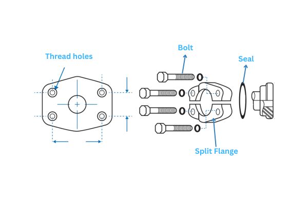
SAE J518 (Code 61 / Code 62)
SAE J518 is a U.S.-based standard specifically designed for high-pressure hydraulic systems. You’ll find it everywhere—from construction machinery to oil rigs. It comes in two pressure ratings:
- Code 61: Rated for systems up to 3,000 PSI
- Code 62: Built for tougher conditions, handling up to 6,000 PSI
Both types use inch-based measurements and share similar bolt hole patterns, but they’re not interchangeable due to differences in flange thickness and pressure capabilities.
Typical use cases include agricultural equipment, mobile hydraulics, and mining operations—anywhere durability and leak-proof connections are non-negotiable.
ISO 6162
ISO 6162 is the international counterpart to SAE J518, using metric dimensions but based on the same design principles.
- ISO 6162-1: Equivalent to SAE Code 61 (for 3000 PSI systems)
- ISO 6162-2: Equivalent to SAE Code 62 (for 6000 PSI systems)
While the two standards appear nearly identical, don’t assume they’re fully interchangeable—minor dimensional differences can cause seal issues. If your components are sourced internationally, double-check you’re matching ISO with ISO—not mixing with SAE unless you’re using compatible adapters.
ANSI / ASME B16.5
This is the go-to flange standard in the U.S. for general industrial use—not limited to hydraulics. It covers a wide range of applications, including oil & gas, chemical processing, and power generation.
- Pressure classes range from 150 to 2500
- Dimensions are in inches
- Commonly used for pipe flanges, not specifically designed for hydraulic use—but still found in heavy-duty fluid systems
Its strength is versatility, but its major downside? It’s completely incompatible with European DIN flanges, despite some visual similarities.
EN 1092 / DIN
This European standard is built for metric-based hydraulic and industrial systems. It’s widely used in Europe, Asia, and international maritime systems. DIN flanges are often required when you’re working on ships, European factories, or global equipment brands.
- Pressure levels are shown as PN (Pressure Nominale): e.g., PN10, PN16, PN25, PN40
- Uses millimeters and bar instead of inches and PSI
- Includes flange types like slip-on, weld-neck, and blind—similar to ANSI, but with different dimensions and pressure tolerances
Major Differences Between American and European Flanges
When someone says, “A flange is a flange,” they’ve clearly never tried matching an ANSI flange to a DIN one. At first glance, American and European flanges might seem similar—but the devil’s in the details. Let’s break down where these standards truly part ways.
Unit of Measurement: Inches vs Millimeters
American standards like ANSI/ASME B16.5 use inches for all dimensions—diameter, bolt spacing, thickness, everything. On the other hand, European standards such as EN 1092-1 / DIN follow the metric system, measuring in millimeters.
This alone makes them tricky to swap. A flange marked 6 inches isn’t the same as DN150—even if they look roughly the same size.
Pressure Ratings: Class vs PN
ANSI flanges rate pressure with Class numbers—like Class 150, 300, 600, all the way up to 2500. These numbers are tied to PSI ratings and vary with temperature.
DIN/EN flanges, however, use PN (Pressure Nominale) values—like PN10, PN16, or PN40—which are pressure ratings measured in bar, typically at ambient temperature.
So even if the physical size matches, a Class 300 flange isn’t automatically equal to a PN40. Mismatching pressure specs can lead to serious system failures.
Bolt Pattern, Thickness & Sealing Face Design
This is where it gets messier.
- Bolt Hole Layout: Even if the bolt count is the same, the bolt circle diameter (BCD) and hole size are often different.
- Thickness: ANSI flanges are generally thicker, especially at higher pressure classes.
- Sealing Face: ANSI flanges may have raised faces or ring-type joint (RTJ) grooves, while DIN flanges often use flat face or smooth finishes, depending on PN rating.
These subtle differences make them mechanically incompatible—even if you manage to get the bolts through.
Regional Engineering Preferences
- In the U.S., engineers, OEMs, and suppliers default to ANSI or SAE flanges.
- In Europe, DIN and EN 1092 are standard practice.
- Global machinery often favors ISO 6162 for compatibility, especially when dealing with international supply chains.
- The shipping industry and marine projects almost exclusively follow DIN.
So if you’re exporting or sourcing globally, knowing your destination’s preferred standard is just as important as knowing the specs.
Why They’re Not Interchangeable
To put it simply: just because two flanges have similar diameters doesn’t mean they fit the same system. Pressure mismatches, sealing issues, and even minor misalignment can lead to leaks, blowouts, or permanent damage.
Bottom line? ANSI and DIN are two different languages, and trying to “translate” between them without adapters or proper redesign usually leads to expensive mistakes.
| Feature | American Flanges (ANSI/ASME) | European Flanges (EN/DIN) |
| Unit of Measurement | Inches (in) | Millimeters (mm) |
| Pressure Rating System | Class (e.g., 150, 300, 600, etc.) | PN (e.g., PN10, PN16, PN25, etc.) |
| Pressure Unit | PSI (pounds per square inch) | Bar (1 bar ≈ 14.5 PSI) |
| Bolt Circle & Hole Layout | Imperial spacing, varies with Class | Metric spacing, varies with PN |
| Flange Thickness | Thicker at higher pressure ratings | Generally thinner |
| Sealing Face Options | Raised Face, RTJ (Ring-Type Joint) | Flat Face or Smooth Face |
| Common Use Region | United States, Canada, Latin America | Europe, Asia, Global Maritime Applications |
| Standard Examples | ASME B16.5, SAE J518 | EN 1092-1, DIN 2501 |
| Interchangeability | ❌ Not compatible with DIN without adapters | ❌ Not compatible with ANSI without adapters |
| Risk of Mixing | Misalignment, leak, pressure failure | Same—can’t assume compatibility |
Compatibility Issues: Why Mixing Standards Is Risky
Mixing hydraulic flange standards might seem like a clever shortcut—especially when you’re in a pinch and the parts look “close enough.” But here’s the harsh truth: in hydraulics, close doesn’t cut it. When you’re dealing with high-pressure systems, even tiny differences in dimensions can spell disaster.
Whether it’s a mismatch in bolt hole layout, a slight variance in flange thickness, or a seal face that doesn’t quite align, the result is the same: leaks, mechanical failures, or catastrophic blowouts. And by the time those issues surface, the damage is already done.
Bolt Misalignment and Sealing Failures
Let’s get specific. Imagine you’ve got an ANSI Class 300 flange, and you’re trying to mate it with a DIN PN40 flange. At a glance, the bolt holes seem to be in the right spot. You grab your wrench and get to work.
But what you don’t see is that the bolt circle diameter (BCD) is slightly off. The holes are a few millimeters too tight, or the thickness of the flanges causes your gaskets to misseat. The sealing face types might also differ—raised face (RF) on the ANSI side vs. a flat face (FF) on the DIN side. These variations may not be visible to the naked eye, but they matter—a lot.
You manage to tighten everything down. No leaks. System starts. Looks like a win… until two weeks later, under full load, a slow drip appears. That drip becomes a leak. Then, under pressure, it blows—releasing high-pressure hydraulic fluid and shutting the system down.
This kind of failure is 100% avoidable—but only if you recognize that standards aren’t suggestions.
Real-World Scenario: The “Forced Fit” Disaster
A marine contractor once tried to retrofit a U.S.-built hydraulic pump onto a European-manufactured ship system. The pump flange followed ANSI Class 600, while the ship’s piping was built to EN 1092 PN40 specs. Instead of sourcing the correct adapter, they took matters into their own hands.
They redrilled the flange holes manually and “forced” the connection into place. It seemed to work at first—until sea trials began.
Just an hour into operation, the flange started leaking. Under pressure, the mismatch caused the seal to shear, resulting in a significant spill. Not only did the ship fail its inspection, but the repair involved dry-docking the vessel, replacing both flange sets, and re-certifying the system.
Total cost: $15,000 in parts and labor, plus three days of lost time. That’s a massive price to pay for trying to skip over standards.
What About Adapters?
Okay, but what if you’re stuck between two systems—say, an American pump and European piping? Are you out of luck?
Not quite. Adapters and transition flanges can bridge the gap—but only if they’re properly designed.
Here’s what a reliable adapter must do:
- Match pressure ratings on both sides (Class to PN, PSI to bar)
- Correct bolt hole spacing without creating mechanical stress
- Maintain seal integrity, often using custom grooves or O-rings
- Withstand vibration, thermal cycling, and pressure surges
But let’s be clear—adapters add cost, increase complexity, and introduce extra failure points. If they’re not properly engineered, they can end up being the weakest part of your system.
If you’re designing a new hydraulic setup or even expanding an existing one, it’s almost always smarter to standardize from the start. Pick one system—SAE, DIN, ISO, or ANSI—and make sure every fitting, flange, and gasket lines up with it. Your future self will thank you.
How to Choose the Right Hydraulic Flange Standard
Choosing the right flange standard isn’t just about ticking boxes on a spec sheet—it’s about preventing future problems, ensuring system integrity, and saving time and money down the road. Here’s how to make the right call, step by step.
Step 1: Where Is the Project Located?
The first question to ask is: Where will this system operate?
- U.S., Canada, or Latin America? → Go with ANSI/ASME or SAE J518.
- Europe, Asia, or international shipping? → You’ll likely need EN 1092-1/DIN or ISO 6162.
Local standards are more likely to be supported by contractors, inspectors, and regional suppliers. That means faster sourcing and fewer headaches during installation.
Step 2: What’s the Pressure Requirement?
This is where things get real. If you’re working with high-pressure hydraulic applications, your flange needs to match the load.
- SAE Code 61 handles systems up to 3000 PSI
- SAE Code 62 handles up to 6000 PSI
- DIN flanges like PN16, PN25, or PN40 are rated in bar (1 bar ≈ 14.5 PSI)
If you’re running a 4000+ PSI system and try to cut corners with PN16 parts, you’re risking a blowout. Match the pressure, not just the size.
Step 3: Is the System Already Using a Standard?
Don’t mix standards.
If you’re connecting to an existing system, stick with the flange standard that’s already in use—whether that’s DIN, SAE, or ANSI. Swapping one part often leads to a domino effect of incompatibility, and you’ll end up needing adapters or reworking everything.
Step 4: What’s Available Through Your Supply Chain?
Let’s be practical. Even if you want ISO flanges, if your local supplier only stocks ANSI, you’re going to face lead times and cost issues.
Ask yourself:
- Which flange types are readily available in your market?
- Can you source fittings and gaskets that match?
- Do you need to import special parts?
Sometimes, availability drives the decision—just don’t compromise on safety or compatibility.
Final Tip: Match the Application, Not Just the Location
While geography and supply are important, the working conditions should lead to the decision. Here’s a simple priority guide:
- Application & Pressure Rating (most critical)
- System Compatibility (avoid mixed standards)
- Regional Engineering Norms
- Availability & Lead Time
Choose the standard that can handle your workload safely, integrate with your current setup seamlessly, and be supported reliably over the long term.
Final Conclusion
In high-pressure hydraulic systems, flange standards aren’t just technical details—they’re the backbone of safe, reliable performance. Whether you’re building a new system or maintaining an existing one, using the correct standard—SAE, ISO, ANSI, or DIN—ensures compatibility, prevents costly failures, and keeps operations running smoothly. Mixing flanges may seem convenient, but it often leads to leaks, downtime, and unexpected expenses.
Need hydraulic flanges that meet global standards and ship fast? Topa offers a full range of SAE, ISO, DIN, and ANSI flanges—precision-machined, pressure-tested, and ready to go. Contact us today to get expert support and high-quality products that fit right the first time.
FAQ
Can I use a DIN flange with an ANSI flange?
No, they are not compatible due to differences in dimensions, bolt patterns, and sealing faces.
What does “PN” mean in DIN flange standards?
PN stands for “Pressure Nominale” and indicates the pressure rating in bar (e.g., PN16 = 16 bar).
What is the difference between SAE Code 61 and Code 62?
Code 61 is rated for 3000 PSI, while Code 62 is for higher-pressure systems up to 6000 PSI.
Are ISO 6162 flanges the same as SAE flanges?
They are very similar. ISO 6162-1 matches SAE Code 61, and ISO 6162-2 matches Code 62, but dimensions may vary slightly.
Can I mix flange standards using an adapter?
Yes, but only if the adapter is professionally engineered and pressure-rated for both standards.
Which flange standard is best for high-pressure systems?
SAE Code 62 and ISO 6162-2 are ideal for systems up to 6000 PSI.