Proper hydraulic flange installation is critical for maintaining the safety, reliability, and performance of your hydraulic system. Even small installation errors can lead to leaks, decreased efficiency, or severe system failures. By ensuring correct alignment, following accurate torque specifications, and using recommended flange assembly procedures, you can significantly enhance equipment longevity, prevent costly downtime, and safeguard workers from potential hazards. Ultimately, mastering the best practices for hydraulic flange installation is key to running a robust, leak-free, and efficient hydraulic system.
Understanding Hydraulic Flange Fittings
What Are Hydraulic Flange Fittings?
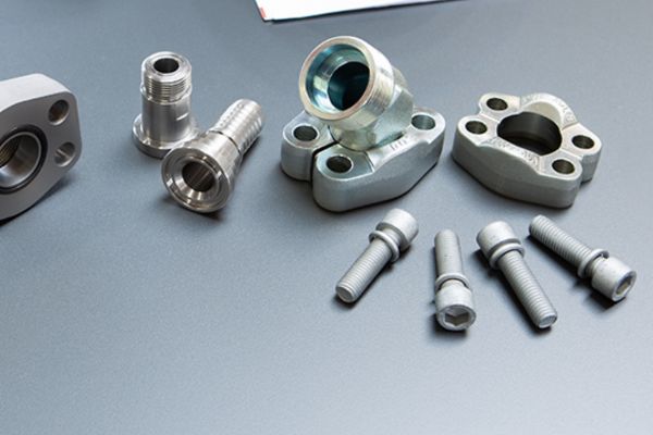
Hydraulic flange fittings are specialized connectors designed for joining tubes, hoses, and pipes in high-pressure hydraulic systems. Unlike traditional threaded fittings, these flanges use bolts and flat surfaces for sealing, creating connections that can reliably withstand extreme pressure and vibration. Typically consisting of a flange head, gasket (usually an O-ring), bolts, and clamp halves, these fittings provide robust sealing solutions that ensure leak-proof, secure connections. Hydraulic flange fittings are favored in various industries because they simplify assembly, facilitate easy maintenance, and offer enhanced sealing capabilities compared to traditional fittings.

SAE J518 Standard: Code 61 vs. Code 62 Flanges
When dealing with hydraulic flange fittings, it’s crucial to understand the SAE J518 standard, which classifies flanges into two primary types: Code 61 and Code 62.
Code 61 Flanges are designed for applications with pressure ratings up to approximately 3000–5000 PSI. They have a lighter-duty bolt pattern and thinner flange thickness, suitable for moderate hydraulic pressures and general industrial equipment.
Code 62 Flanges, in contrast, are intended for more demanding high-pressure applications, accommodating pressures up to 6000 PSI. They feature heavier, more robust construction with a thicker flange and a bolt pattern designed to withstand significantly greater stresses and pressures.
It’s vital to note that despite visual similarities, Code 61 and Code 62 flanges are not interchangeable due to their differing bolt patterns, dimensions, and sealing requirements. Incorrectly interchanging them can lead to leaks, premature failure, or even safety hazards.
Applications: From High-Pressure Flanges to Hydraulic Hose Fittings
Hydraulic flange fittings are widely utilized across numerous industries, particularly in environments requiring high-pressure performance and vibration resistance. Typical applications include construction equipment, heavy machinery, mining operations, industrial hydraulic presses, agricultural machinery, oil and gas installations, and marine systems.
In hydraulic systems requiring high-pressure flanges, such as heavy-duty earthmoving machinery or drilling equipment, Code 62 flanges are preferred due to their enhanced strength and sealing capabilities. Conversely, Code 61 flanges are suitable for less extreme applications, like industrial hydraulic power units and moderate-pressure mobile equipment.
Additionally, hydraulic flange fittings are commonly paired with hydraulic hoses, offering secure and robust connections that can be easily serviced and maintained. They play a critical role in ensuring system integrity, reducing maintenance downtime, and improving overall reliability.
Essential Tools & Equipment for Hydraulic Flange Installation
Torque Wrench Settings: Ensuring Accuracy
Accurate torque wrench settings are the cornerstone of successful hydraulic flange installations. A torque wrench precisely measures the amount of force applied when tightening bolts, ensuring each bolt meets the manufacturer’s exact torque specifications. Using the correct torque wrench settings helps you achieve optimal sealing without risking damage to the flange or bolts. Improper torque can lead to overtightening, causing distortion, stress fractures, or under-tightening, which results in leaks or even bolt loosening during operation. To achieve consistent and reliable results, always follow the recommended torque specifications outlined in the flange torque chart provided by the manufacturer or the SAE J518 standard.
Importance of Torque Calibration and Verification
Regular calibration and verification of your torque wrench are essential yet frequently overlooked aspects of hydraulic flange installation. Even minor inaccuracies in your torque wrench can lead to substantial deviations in bolt tightness, significantly affecting flange performance and system reliability. Calibration ensures your torque wrench accurately applies the specified torque, safeguarding flange joints against potential leaks and failures. Regular verification, ideally at scheduled intervals or before critical installations, guarantees consistent accuracy and dependable outcomes. By prioritizing torque wrench accuracy, you’ll protect the integrity of your hydraulic connections, improve operational safety, and minimize maintenance costs over the long term.
Selecting the Right Bolts: ISO 616 Bolts & Beyond
Choosing the right bolts for your hydraulic flange installation is just as critical as using proper torque settings. ISO 616 bolts, widely recognized in hydraulic systems, are specially designed to provide superior strength, corrosion resistance, and reliability under high-pressure and vibration conditions. Selecting bolts compliant with ISO 616 standards or equivalent ensures compatibility, optimal load distribution, and lasting integrity of the flange connection. Beyond standardization, it’s crucial to match bolt length, material strength, and thread lubrication to your specific application. Proper bolt selection combined with accurate torque settings reduces the risk of mechanical failure, leakage, and costly downtime. Always refer to industry guidelines, flange specifications, and torque tables to choose bolts that meet your system’s exact requirements and operating environment.
Step-by-Step Flange Assembly Procedure
Preparing Flange Surfaces: Ensuring Proper Flange Alignment
- Inspect the flange faces for visible damage, scratches, corrosion, or debris.
- Clean both flange surfaces thoroughly using an appropriate solvent or cleaner to eliminate oil, dust, or contaminants.
- Ensure the flange surfaces are smooth, flat, and parallel, checking alignment carefully to confirm they are evenly matched.
- Remove any protective caps or coverings immediately before installation to prevent contamination.
- Use alignment tools or jigs for larger flanges to maintain proper positioning and stability during assembly.
- Perform a final visual inspection to verify alignment accuracy before proceeding to gasket installation.

Gasket Installation: O-Ring Flanges and Flange Sealing Methods
- Inspect the O-ring gasket carefully for any defects, including cuts, tears, abrasions, or signs of deterioration.
- Lightly lubricate the gasket with hydraulic fluid or a compatible lubricant to prevent damage during installation.
- Position the gasket securely into the flange groove, ensuring it is fully seated without bulging, stretching, or twisting.
- Double-check gasket alignment, confirming it is evenly seated around the entire circumference.
- Confirm gasket compatibility with the flange specifications and hydraulic fluid type to ensure effective sealing.
Thread Lubrication: Small Detail, Big Difference
- Choose a recommended thread lubricant (e.g., anti-seize compound or high-pressure grease) compatible with hydraulic flange bolt threads.
- Apply lubricant evenly and sparingly to the bolt threads and the underside of bolt heads, avoiding excess buildup.
- Avoid contaminating flange faces or gaskets with lubricant to maintain optimal sealing integrity.
- Ensure consistent lubricant application across all bolts for uniform torque accuracy and balanced tightening force.
- Regularly inspect and replenish lubricant during maintenance checks to maintain ongoing flange joint reliability.
Bolt Torque Sequence & Tightening Patterns
Understanding Tightening Torque Specifications
Accurately understanding tightening torque specifications is essential to creating secure, leak-proof hydraulic flange installations. Torque specifications indicate the precise amount of rotational force required to tighten bolts, ensuring optimal flange sealing without risking damage. These specifications vary depending on flange type, bolt size, and the material involved. Adhering strictly to these guidelines helps prevent uneven bolt loads, flange distortion, and potential leaks or failures under pressure. Always consult the manufacturer’s specifications or SAE J518 standards to ensure you’re applying the correct torque settings.
Torque Table Guide: Quick Reference for Code 61 & Code 62 Flanges
Having a clear and accessible torque table simplifies your hydraulic flange installation, especially when dealing with Code 61 and Code 62 flanges. Here’s a quick-reference guide based on common flange sizes:
Code 61 (3000–5000 PSI):
| Line size | Flange size | BS bolt(J518) | Torque (Nm) | Metric bolt(ISO 616) | Torque (Nm) |
| 8 | 1/2″ | 5/16-18 | 17±2 | M8 | 25 |
| 12 | 3/4″ | 3/8-16 | 25±4.5 | M10 | 49 |
| 16 | 1″ | 3/8-16 | 31±4.5 | M10 | 49 |
| 20 | 1.1/4″ | 7/16-14 | 41±5 | M10 | 85 |
| 24 | 1.1/2″ | 1/2-13 | 52±6 | M12 | 85 |
| 32 | 2″ | 1/2-13 | 60±6 | M12 | 92 |
| 40 | 2.1/2″ | 1/2-13 | 85±9 | M12 | 92 |
| 48 | 3″ | 5/8-11 | 144±15 | M16 | 220 |
| 56 | 3.1/2″ | 5/8-11 | 125±8 | M16 | 220 |
| 64 | 4″ | 5/8-11 | 125±8 | M16 | 220 |
| 80 | 5″ | 5/8-11 | 125±8 | M16 | 220 |
Code 62 (6000 PSI):
| Line size | Flange size | BS bolt(J518) | Torque (Nm) | Metric bolt(ISO 616) | Torque (Nm) |
| 8 | 1/2″ | 5/16-18 | 17±2 | M8 | 25 |
| 12 | 3/4″ | 2003/8/16 | 30±4.5 | M10 | 49 |
| 16 | 1″ | 7/16-14 | 46±4.5 | M12 | 85 |
| 20 | 1.1/4″ | 2001/2/13 | 69±6 | M12 | 135 |
| 24 | 1.1/2″ | 2005/8/11 | 125±8 | M16 | 210 |
| 32 | 2″ | 2003/4/10 | 208±20 | M20 | 425 |
Keep this torque table handy during installations to quickly verify torque values and streamline your flange assembly process.
Tightening Cross Pattern: Ensuring Uniform Pressure
The tightening cross pattern is essential for evenly distributing bolt pressure across the flange surfaces. Applying torque in a cross or diagonal sequence ensures the flange surfaces compress evenly, significantly reducing the risk of leaks, flange distortion, or gasket damage. Follow these steps:
- Start with hand-tightening all bolts until the flange surfaces make uniform contact.
- Use a calibrated torque wrench to tighten bolts incrementally in a crisscross pattern, applying torque in stages (30%, 60%, and finally 100% of the required torque).
- Double-check torque on each bolt to verify uniformity and correct torque levels.
- Perform a final torque inspection after initial pressure tests or operation cycles, retightening if necessary.
Consistently using this tightening pattern guarantees balanced pressure, enhances sealing performance, and ensures long-term flange reliability.
Preventing Hydraulic Connection Leaks & Failures
Leakage Prevention: Hydraulic Sealing Technology Explained
Hydraulic sealing technology plays a crucial role in preventing leaks within hydraulic flange connections. Effective sealing solutions typically rely on precision-engineered components, such as O-ring gaskets, which are specifically designed to withstand high pressures and dynamic operating conditions. Here’s how you can maximize sealing effectiveness:
- Choose the right gasket material: Ensure compatibility with hydraulic fluid, temperature extremes, and operating pressures.
- Inspect gaskets thoroughly: Replace any gasket showing signs of wear, deformation, or damage.
- Lubricate seals correctly: Apply a thin film of hydraulic fluid or approved lubricant to O-rings during installation to prevent damage.
- Adhere strictly to flange torque specs: Accurate bolt torque ensures optimal sealing compression and prevents gasket distortion.
Ensuring Vibration Resistance and Durability
Hydraulic systems often operate in high-vibration environments, which can weaken connections over time. To enhance flange durability and resist vibration-induced failures:
- Select robust flange fittings: Prefer Code 62 flanges for high-vibration and high-pressure applications.
- Implement proper bolt tightening sequences: The cross-tightening pattern distributes load evenly, minimizing loosening from vibration.
- Consider vibration dampening measures: Use mounting brackets, clamps, or anti-vibration mounts to stabilize hydraulic hoses and fittings.
- Regularly inspect connections: Monitor bolt torque periodically to detect and address loosening before leaks occur.
Flange Inspection Techniques: Spotting Issues Early
Proactive inspection is your best defense against leaks and hydraulic failures. Regular flange inspections enable early detection and swift correction of potential issues:
- Conduct visual inspections routinely: Check for signs of leaks, corrosion, bolt damage, or flange misalignment.
- Utilize torque verification: Periodically verify bolt torque using a calibrated torque wrench to ensure connections remain secure.
- Perform scheduled pressure tests: Apply pressure testing procedures periodically to confirm sealing integrity.
- Implement predictive maintenance practices: Utilize tools like ultrasonic leak detection or infrared imaging to identify hidden issues early.
By consistently applying these flange inspection techniques, you’ll maintain reliable hydraulic connections, extend equipment lifespan, and significantly reduce downtime.
Troubleshooting Common Hydraulic Flange Issues
Diagnosing and Correcting Flange Alignment Problems
Flange misalignment is a frequent issue causing leaks and system inefficiencies. Identifying alignment problems early and correcting them effectively is critical:
- Visual inspection: Check flange surfaces for uneven gaps, visible misalignment, or stress marks.
- Use alignment tools: Alignment jigs, rulers, or laser alignment devices can pinpoint precise misalignments.
- Check bolt pattern: Uneven bolt tightening can cause alignment shifts—loosen bolts, realign flanges carefully, and retighten evenly.
- Surface preparation: Remove dirt, corrosion, or surface irregularities that might interfere with proper alignment.
- Corrective actions: Adjust flange positions, replace damaged flanges, or upgrade alignment support mechanisms when needed.
Addressing Bolted Joint Assembly Failures
Failures in bolted flange joints can lead to serious hydraulic leaks or operational hazards. Here’s how to diagnose and resolve these issues quickly:
- Bolt inspection: Regularly check for signs of thread damage, elongation, or overtightening.
- Torque verification: Confirm bolts meet specified torque levels using a calibrated torque wrench.
- Evaluate gasket condition: Inspect O-ring seals or other gasket types for proper seating and integrity.
- Address thread galling or corrosion: Lubricate bolt threads correctly and replace any compromised bolts or threads.
- Consider joint redesign: If failures persist, evaluate flange or bolt specifications and consider upgrading flange class or materials.
Quick Fixes vs. Professional Solutions: Making the Right Call
Deciding whether to apply quick fixes or seek professional assistance is essential for effective troubleshooting:
- Quick Fixes (Temporary):
- Minor bolt re-tightening
- Surface cleaning and gasket reseating
- Realignment adjustments without disassembly
- Professional Solutions (Permanent):
- Replacing damaged flanges, bolts, or gaskets
- Professional torque recalibration and verification
- Comprehensive system pressure testing and leak detection
Knowing when to choose immediate corrective actions or invest in professional servicing can save significant downtime and costs, ensuring long-term reliability and safety for your hydraulic system.
Conclusion
Remember, investing in accurate tools, following recommended torque practices, and staying vigilant about routine inspections isn’t merely beneficial—it’s essential. Adopting these best practices ensures your hydraulic flange installations remain robust and dependable under pressure, ultimately contributing to a safer and more productive workplace.
If you need high quality hydraulic flanges, welcome to contact Topa, we can provide the highest quality products!
FAQ
What is the difference between Code 61 and Code 62 flanges?
Code 61 flanges handle lower pressures (up to around 3000–5000 PSI), while Code 62 flanges are designed for high-pressure applications (up to 6000 PSI).
How often should I check the torque on hydraulic flange bolts?
It’s best to verify bolt torque after initial installation, after the first operational cycle, and periodically (every 6–12 months) thereafter.
Why is thread lubrication important in flange installations?
Lubrication reduces friction, ensures accurate torque application, prevents thread galling, and helps maintain consistent bolt tightness.
Can improper flange alignment cause leaks?
Yes, even slight misalignment can lead to uneven gasket pressure, resulting in leaks and eventual system failures.
What are common signs of flange installation errors?
Visible leaks, loose bolts, uneven flange gaps, vibration issues, and premature gasket wear are typical signs of installation problems.
Can I reuse flange bolts and gaskets?
It’s not recommended—always use new gaskets and inspect bolts thoroughly. Replace bolts that show signs of damage, corrosion, or thread wear.