Are you tired of dealing with persistent hydraulic leaks, but can’t quite pinpoint why your threaded connections loosen or weep fluid? Often, the solution lies in a hidden detail: the thread class.
Understanding thread classes like 1B, 2B, and 3B is crucial for leak prevention in hydraulic systems. Choosing the correct thread class ensures a precise fit, uniform sealing, and long-term reliability in your connections, directly combating the frustrating problem of hydraulic fluid leakage.
What Do 1B, 2B, and 3B Threads Designation Really Mean?
Have you ever seen “1B” or “2B” stamped near a threaded hole and wondered what it signified beyond just a size?
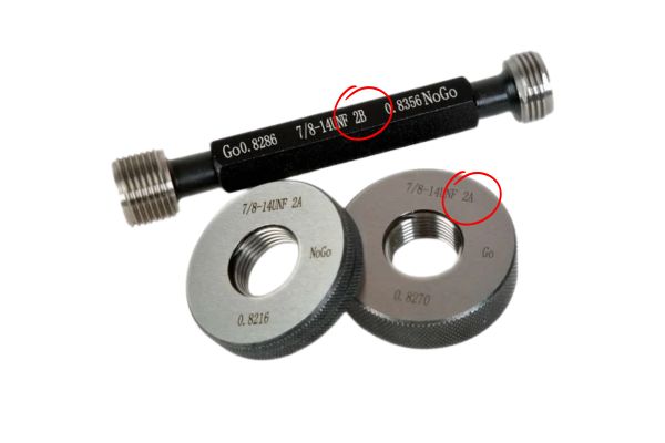
In American National Standard (UN/UNR) threads, designations like 1B, 2B, and 3B define the internal thread’s (hole or nut) tolerance class, with “B” indicating internal threads and the number (1, 2, or 3) indicating the precision or looseness of the fit. Understanding these basic elements is the first step toward creating secure, leak-resistant hydraulic connections.
At its core, a thread designation combines a number and a letter, each carrying a specific meaning crucial for engineering and assembly. These designations are part of the Unified Thread Standard (UTS), which is widely used in the United States and Canada. This system ensures interchangeability and compatibility between different manufactured components.
Unpacking the Code
The Number (1, 2, or 3):
Represents the Tolerance Class (also known as Precision Grade).
This number indicates the permissible range of variation in the thread’s form, pitch, major diameter, and minor diameter. It dictates how tightly or loosely the threads will fit together when assembled with an external thread (like a bolt or a fitting’s male end).
A higher number (e.g., 3) signifies a tighter tolerance and higher precision. This means the manufacturing process must be more controlled, resulting in a thread that deviates very little from its theoretical perfect form. This tighter control creates a connection with minimal clearance.
A lower number (e.g., 1) signifies a looser tolerance and lower precision. This allows for greater variation in manufacturing, resulting in a thread with more clearance. This provides a more forgiving fit, especially in conditions where minor imperfections might exist.
The Letter (B):
Designates Internal Threads.
The capital letter “B” specifically refers to internal threads, which are those machined into a hole (like a hydraulic port on a valve body) or found inside a nut. When you see “B,” you know you are looking at a female thread.
Conversely, for external threads (like those on a bolt, a male hydraulic fitting, or a threaded rod), the letter “A” is used (e.g., 1A, 2A, 3A). These terms “A” and “B” always denote whether the thread is male or female, regardless of the precision level.
| Symbol | Thread Type | Precision / Tolerance |
| 1A | External (Male) | Loose tolerance, lowest precision |
| 2A | External (Male) | General-purpose tolerance |
| 3A | External (Male) | Tight tolerance, highest precision |
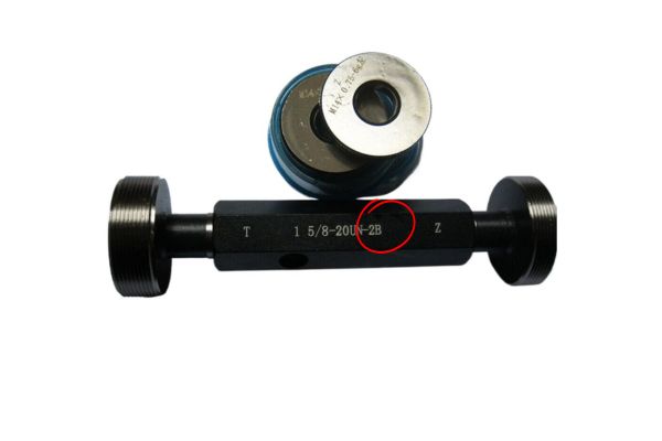
| 1B | Internal (Female) | Loose tolerance, lowest precision |
| 2B | Internal (Female) | General-purpose tolerance |
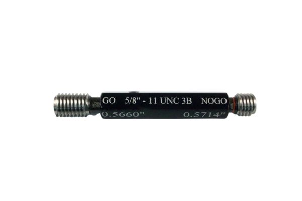
| 3B | Internal (Female) | Tight tolerance, highest precision |
How Does Each Thread Class Impact Seal Integrity and Leak Prevention?
Are you struggling with leaks because components feel too loose or too tight? Understanding the inherent fit difference between 1B, 2B, and 3B threads is key to achieving leak-free hydraulic connections.
The core difference among 1B, 2B, and 3B lies in their manufacturing tolerances: 1B offers the loosest fit for easy assembly in non-critical scenarios, 2B provides a balanced, general-purpose fit ideal for most hydraulic applications to prevent leaks, and 3B delivers the tightest, most precise fit for critical, high-performance systems requiring maximum leak prevention and stability.
Here is a breakdown of the core differences and their implications for leak integrity:
| Feature | 1B Class (Internal Thread) | 2B Class (Internal Thread) | 3B Class (Internal Thread) |
| Tolerance Level | Loosest Tolerance: Largest permissible variation. | General Tolerance: Balanced and practical. | Tightest Tolerance: Smallest permissible variation. |
| Fit Nature | Loose Fit: Significant clearance (larger major, minor, pitch diameters). Easy to assemble. | General Purpose Fit: Small but definite clearance. Smooth assembly. | Tight Fit/Zero Clearance: Minimal to no practical clearance. Very secure. |
| Leak Prevention Performance | Lower: Higher clearance can lead to weeping under pressure or loosening from vibration, making consistent sealing challenging without additional measures. | Good: Designed to provide sufficient contact for reliable sealing when matched correctly. Standard for general-purpose leak prevention. | Excellent: Minimal clearance provides maximum contact, crucial for preventing leaks under high pressure/vibration and for anti-loosening. |
| Common Application | Rough applications, dirty environments, quick assembly, or parts requiring subsequent thick coatings (e.g., hot-dip galvanizing for pipes) where thread clearance is needed. | Universal Standard: The most widely used grade for general engineering, suitable for the vast majority of hydraulic fitting applications where reliable sealing is required. | Critical applications where safety, reliability, and precision are paramount, such as aerospace, military, and high-precision instruments where any leak is unacceptable. |
Matching Internal and External Threads for a Leak-Proof Connection
Do your hydraulic fittings sometimes feel too loose, too tight, or even jam when you try to assemble them? Improperly matched thread classes are likely the culprit, leading directly to leaks and connection failure.
For a leak-proof and durable hydraulic connection, the internal thread (B class) must be correctly paired with the external thread (A class). This ensures the optimal fit, balancing ease of assembly with the required sealing integrity, and preventing issues like stripping, galling, or eventual leakage that arise from mismatches.
Understanding the “A” Classes (External Threads):
Just as “B” denotes internal threads, “A” denotes external threads (like those on bolts, machine screws, or the male ends of hydraulic fittings). The numbers (1, 2, 3) signify the same tolerance levels as with “B” classes:
- 1A: Loosest tolerance, most clearance.
- 2A: General purpose tolerance, slight clearance. Most common.
- 3A: Tightest tolerance, minimal clearance.
Critical Matching Principles for Leak Prevention
The goal is to achieve an appropriate “fit” (loose, free, or tight) that supports the sealing mechanism (whether it’s thread engagement itself, a face seal, or a thread sealant) and dynamic conditions.
1B Internal Thread → Pair with 1A or 2A External Thread
This combination is designed for very easy assembly, even with threads that are slightly damaged, dirty, or have a thick coating (like heavy paint or hot-dip galvanizing).
Leak Implication: The significant clearance in this fit means it offers very limited inherent leak prevention. For hydraulic systems, this combination would almost certainly require additional external sealing methods (like an O-ring on a face, or copious amounts of thread sealant) to prevent weeping.
2B Internal Thread → Pair with 2A External Thread
This is the standard, most versatile, and widely recommended combination for the vast majority of commercial and industrial applications, including hydraulic fittings.
Leak Implication: The “free fit” provides enough clearance for smooth, easy assembly without excessive play. This allows for good thread engagement, ensuring that thread sealants can fill the spaces effectively. It offers a reliable and consistent seal when tightened properly.
3B Internal Thread → Must Pair with 3A External Thread
This combination offers the smallest clearances and results in the tightest possible fit. It is designed for applications where precise alignment, maximum thread engagement, and superior resistance to loosening under extreme conditions are paramount.
Leak Implication: This “tight fit” excels at preventing leaks in critical, high-pressure, or high-vibration hydraulic systems. The minimal clearance offers very effective metal-to-metal contact, enhancing anti-vibration properties and forming an exceptionally robust connection that significantly reduces the potential for fluid escape through the threads.
Critical Warning: Avoid Mismatches!
High-Precision Internal (3B) with Low-Precision External (1A or 2A): This is a critical mismatch. A 3B internal thread has very little allowance. If you try to assemble it with a looser 1A or 2A external thread (which has more manufacturing variation), the larger physical dimensions allowed by the 1A/2A tolerance might interfere with the tight 3B internal thread. This often results in:
- Galling: The material seizes and smears as surfaces try to slide past each other, permanently damaging both threads.
- Cross-Threading: Threads misalign and cut into each other, destroying the connection.
- Incomplete Engagement: Even if it feels tight, the threads might not be fully engaged, leading to a weak connection that will eventually leak or fail.
- Solution: Always pair a 3B internal thread with a 3A external thread.
By diligently selecting matching A and B thread classes, particularly using the widespread 2A/2B combination for general purpose, or the precise 3A/3B for critical applications, you can effectively manage thread clearances to prevent the common issues that lead to hydraulic leaks.
Why 2B Threads Are the Go-To Standard for Most Hydraulic Fittings
Are you debating which thread class to specify for your everyday hydraulic fittings, worrying about potential leaks or assembly issues? For 95% of applications, the 2B thread class is the undisputed best choice.
The 2B thread class is the ultimate standard for most hydraulic fittings because it delivers an optimal balance of precise fit, ease of assembly, and consistent sealing performance.
The Perfect Compromise for Leak Prevention
The unique characteristics of 2B contribute directly to preventing leaks in everyday scenarios.
| Key Feature | Description | Benefit |
| Balanced Manufacturing Tolerance | Tight enough for precision, but not excessively costly or difficult to produce | Reliable sealing + cost-effective |
| “Free Fit” Assembly | Smooth hand-threading, with clearance for sealants (PTFE tape, pipe dope) | Easy installation, reduced cross-threading, better sealing |
| Robust for General Applications | Withstands typical industrial pressures, vibration, and temperature ranges | Consistent performance in machinery, mobile equipment, agriculture |
| Minimizing Risk of Error | Widely recognized standard, easy to source, familiar to technicians | Reduces mismatches, sourcing issues, and assembly mistakes |
When to Rely on 2B
- General Hydraulic Fittings: This includes JIC, ORFS, NPT (if compatible with the overall system design), and most other common hydraulic connection types.
- Valve and Pump Ports: The threaded ports on many standard hydraulic valves, pumps, and cylinders are typically specified with 2B internal threads.
- Mobile Equipment: Agricultural machinery, construction equipment, forklifts, and industrial vehicles commonly use 2B threads for their hydraulic connections.
- Assembly Line Production: Where speed and consistency of assembly are important, 2B threads offer the ideal balance.
When Do 3B Threads Prevent Leaks in Critical Applications?
The 3B thread class is crucial for preventing leaks in highly critical hydraulic applications where extreme precision and maximum connection stability are absolute necessities. Its minimal clearance provides superior resistance to loosening from intense vibration or pressure fluctuations, making it indispensable for aerospace, military, and precision instrument systems where zero leakage is non-negotiable.
While the 2B thread class serves as an excellent general-purpose solution for leak prevention, there are specific, high-stakes scenarios where its inherent clearances might be insufficient. In these environments, even a minor leak could lead to catastrophic failure, compromise safety, or disrupt highly sensitive operations. For such critical applications, the 3B thread class emerges as the ultimate answer. Its meticulously tight tolerance, when properly matched with a 3A external thread, delivers a level of connection integrity and leak resistance that justifies its higher manufacturing cost and more demanding assembly requirements.
Where 3B Threads Make the Difference for Leak Prevention
The enhanced precision of 3B directly translates to superior leak resistance in challenging conditions.
| Application Scenario | Why 3B is Preferred | Key Benefit |
| Aerospace & Defense Systems | Aircraft hydraulics, missile guidance, and military vehicles demand zero leakage under high vibration and extreme pressure surges | Mission-critical safety, maximum vibration resistance |
| High-Precision Instrumentation | Scientific devices, medical tools, robotics require absolute sealing to avoid measurement or motion errors | Maintains accuracy and stability, leak-free |
| High-Vibration, High-Pressure Equipment | Forging presses, hydraulic test stands, shock-loaded machinery | Superior anti-loosening fit, prevents leaks under constant vibration |
| Applications Requiring Maximum Fatigue Life | Repeated stress cycles in heavy-duty systems | Uniform load distribution, prevents micro-cracks, extends fatigue life |
How Other Standards Tackle Leak Prevention Through Tolerances
Are you only familiar with 1B, 2B, 3B, but work with hydraulic systems from around the world? Different thread standards use their own methods to define precision, all aiming for leak-free connections.
While 1B, 2B, and 3B are unique to American National Unified (UN/UNR) threads, other global standards like Metric and British threads use similar principles of tolerance and fit to prevent leaks. Metric threads use alphanumeric “tolerance grades” (e.g., 6H for internal threads), while British threads have their own legacy classification systems, all designed to ensure precise mating for reliable fluid sealing.
Metric Threads (ISO Metric Screw Threads)
Metric threads, defined by ISO (International Organization for Standardization), are the most widely used thread standard globally. They employ a more detailed system of “tolerance grades” and “tolerance positions” to define clarity.
- Tolerance Grade (Number): This indicates the size of the tolerance zone. A lower number (e.g., 4) means a smaller tolerance zone (tighter precision), while a higher number (e.g., 8) means a larger tolerance zone (looser precision).
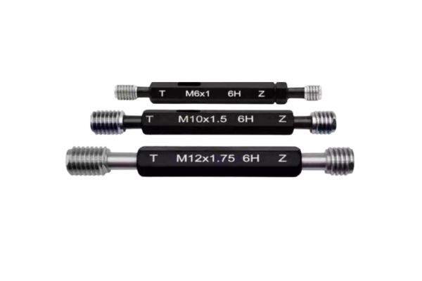
- Tolerance Position (Letter): This indicates the position of the tolerance zone relative to the nominal thread size, influencing the amount of clearance. For internal threads (nuts, ports), capital letters are used, with ‘H’ typically denoting a “zero” fundamental deviation (meaning the tolerance zone starts at the nominal dimension) and ‘G’ denoting a slight positive deviation (meaning the tolerance zone is slightly offset to provide more clearance).
- Common Metric Internal Thread (for Leak Prevention): The most common tolerance class for general-purpose metric internal threads, equivalent in application to the 2B in UN threads, is **6H**.
British Whitworth Threads (BS 84 / BS 93)
Historically, British Whitworth threads (W or BSW) were used extensively, though they are less common in new designs today, especially in hydraulics, as metric and UN threads dominate. Whitworth threads have a 55-degree flank angle, distinct from the 60-degree angle of UN and Metric threads. They also had their own “fit” classifications.
- Older British Standard (BS 84): Used “Close Fit” (Class 1), “Medium Fit” (Class 2), and “Free Fit” (Class 3).
- Newer British Standard (BS 93): Introduced “Precision Mechanical Engineering Fit” (Tight), “General Engineering Fit” (Medium), and “High-Duty Fasteners Fit” (Free).
Pipe Threads (NPT/NPTF, BSPT, BSPP)
Pipe threads are a separate category of threads specifically designed for fluid conveyance and sealing, often differing significantly from parallel (straight) mechanical threads.
- Tapered Pipe Threads (e.g., NPT, NPTF, BSPT): These threads seal by the wedging action of their tapered flanks. When tightened, the male and female tapered threads compress to form a metal-to-metal seal. Due to the inherent taper, they don’t use 1B/2B/3B or 6H/6g classifications in the same way. Their sealing integrity relies on the quality of the taper, the number of turns engaged, and the use of thread sealant (like PTFE tape or pipe dope) to fill the spiral leak path. NPTF (National Pipe Taper Fuel) threads are designed to seal without sealant (dryseal), by having crest and root interference.
- Parallel Pipe Threads (e.g., BSPP, G threads): These are straight threads and typically use a face seal (O-ring, washer, or bonded seal) to prevent leaks, rather than relying on thread engagement for the primary fluid seal. They may have tolerance classes (e.g., G-A, G-B) for dimensional fit, but this influences assembly, not the primary sealing mechanism.
Summary Comparison Table
| Feature | American (UN/UNR) | Metric (ISO) | British (Whitworth) | Pipe Threads (e.g., NPT, BSPT) |
| Internal Thread Designation | 1B, 2B, 3B | 4H, 5H, 6H, 7H | Defined by Fit Classes (e.g., Close, Medium, Free) | No specific parallel classification; Tapered rely on taper seal |
| Most Common Internal Grade | 2B | 6H | Medium / General Engineering Fit | N/A (rely on form/sealant) |
| External Thread Designation | 1A, 2A, 3A | 4h, 6g, 6e, 6f | Defined by Fit Classes | N/A |
| Most Common External Grade | 2A | 6g | Medium / General Engineering Fit | N/A |
| Primary Sealing Mechanism | Thread engagement (often with face seal or sealant) | Thread engagement (often with face seal or sealant) | Thread engagement (often with supplemental seal) | Tapered: Thread wedging/sealant; Parallel: Face seal |
| Flank Angle | 60° | 60° | 55° | NPT/BSPT: 60°/55° |
Conclusion
Regardless of the thread standard (UN, Metric, or Pipe threads), diligently matching internal and external threads and adhering to proper installation practices are paramount for achieving and maintaining leak-free hydraulic systems.
Are you ready to permanently solve your hydraulic leak problems by making informed choices about your threaded connections? Contact the Topa team today to discuss your requirements and discover how our precision-engineered hydraulic fittings can enhance the leak integrity and performance of your hydraulic systems.