How to Read Hydraulic Hose Markings Correctly

How to Read Hydraulic Hose Markings Correctly?

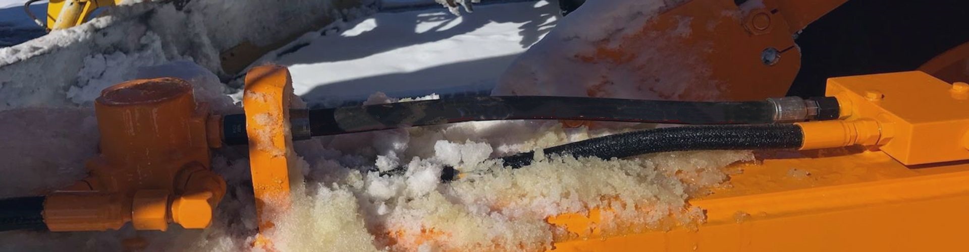
That long line of text printed on a hydraulic hose looks like a secret code. Ordering the wrong replacement because you misread it leads to costly downtime, shipping delays, and even dangerous system failures.

This “layline” is actually a simple guide to everything you need to know. We will teach you how to decode it. By understanding the standard, construction, size, and pressure rating, you can select the perfect hose every time with complete confidence.

Hydraulic Hose Laylines

The layline is your most critical tool when identifying or replacing a hydraulic hose. It’s a permanent marking applied by the manufacturer that details the hose’s capabilities and specifications. Getting this right is fundamental to purchasing, maintenance, and safe operation.

What Are the Key Parts of a Hose Layline?

You see a string of codes like “EN 853 2SN DN13 38 MPa,” and it’s overwhelming. Guessing what it means can lead to buying a hose that doesn’t fit or can’t handle the pressure.

This code is your hose’s data sheet, printed right on its side. It tells you the standard it was built to, how it’s constructed, its size, and its maximum pressure. Understanding these four parts is the key to cracking the code.

SAE 4SP hydraulic hoses Topa

Think of the layline as a universal language for hydraulic professionals. Once you learn the basic vocabulary, you can look at a hose from any major manufacturer and know exactly what it is. This knowledge empowers you to source replacements confidently from different suppliers, knowing you are getting a part that meets your performance and safety requirements. It removes the guesswork from a critical part of your job and ensures your machinery runs smoothly.

The Governing Standard

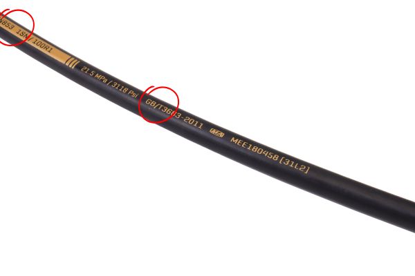
The first piece of information is often the manufacturing standard. This tells you which set of rules the hose was designed and tested against. Common standards include:

The Hose Construction and Type

This part of the code tells you what the hose is made of, specifically its reinforcement. Codes like “R2AT,” “2SN,” or “4SP” describe the number and type of reinforcement layers. This directly relates to the hose’s pressure rating and flexibility. We will dive deeper into these codes in the next sections.

The Hose Size (Inner Diameter)

The size indicates the inner diameter (I.D.) of the hose. This is crucial for ensuring the correct flow rate in your system. Size can be listed in several ways:

The Pressure Rating

This number tells you the maximum working pressure the hose is designed to handle safely. It is usually listed in either Megapascals (MPa) or pounds per square inch (PSI). This is perhaps the most critical safety specification on the hose, and it should never be ignored.

How Do I Decode a Common SAE Hose Marking?

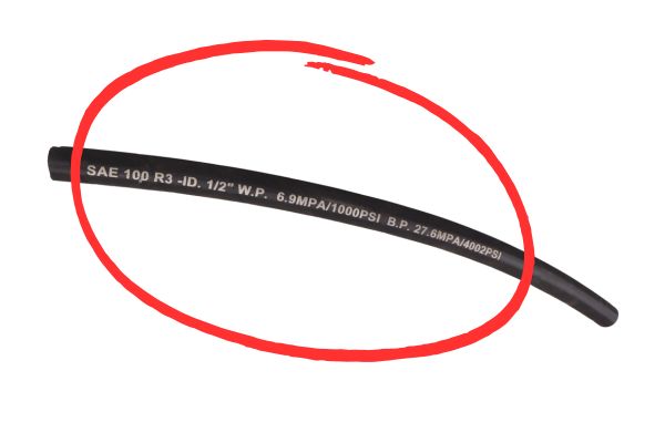
You have a hose marked “SAE 100R2AT -08,” and you need an exact replacement. Not knowing what “R2AT” means could lead you to buy a less durable hose that fails prematurely.

This is one of the most common hose types in North America. “SAE 100” is the standard, “R2” means it has two layers of steel wire braid reinforcement, “AT” specifies certain details, and “-08” means the inner diameter is 1/2 inch.

SAE hose standard

The SAE J517 standard defines a series of “100R” hose types. Each type has specific construction and performance requirements. Understanding these common codes will allow you to identify the vast majority of hoses used on American-made equipment. It’s the foundational knowledge for any maintenance professional working with hydraulics. Once you learn this, the rest of the puzzle starts to fall into place.

The “SAE 100R” Series Standard

The SAE 100R designation is a family of hose types. The number after the “R” indicates the specific construction and application. For example:

Decoding the Type “R2”

The “R2” in our example is very specific. It tells a buyer or user that the hose is reinforced with two layers of high-tensile steel wire braid. This is a very common construction for medium-to-high pressure applications on equipment like tractors, skid steers, and industrial machinery. A hose marked “R1” would have only one layer and a lower pressure rating.

What the “AT” Suffix Means

The “AT” suffix is a detail from older versions of the SAE standard. It technically meant that the outer rubber cover did not need to be “skived” (shaved off) before attaching a fitting. Today, almost all modern hoses are non-skive. While the “AT” is often still printed on the hose for legacy reasons, R1 and R2 hoses are now generally grouped under the EN standards of 1SN and 2SN, which we will cover next.

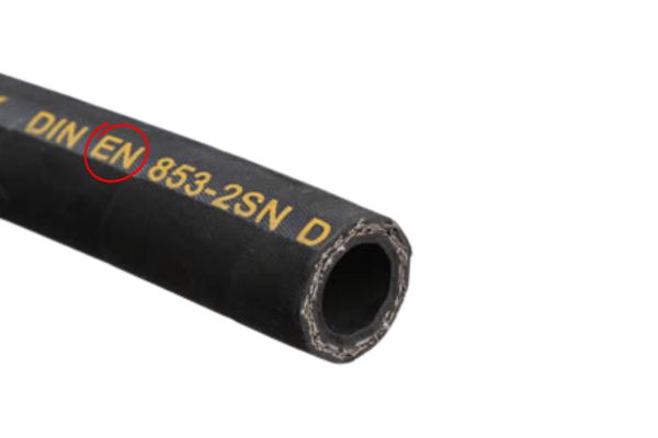
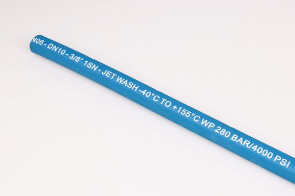
What About European EN Hose Standards?

You’re working on a European machine and the hose is marked “EN 853 2SN DN12.” This looks different from the SAE code you’re used to, and you need to find a compatible replacement.

This is a European standard hose. “EN 853” is the spec for wire braid hoses, “2SN” means it has two layers of wire braid (similar to R2AT), and “DN12” is the nominal size, corresponding to a 1/2 inch or -08 dash size.

en hose standard

European Norm (EN) standards have become globally prevalent, and many manufacturers now produce hoses that meet both SAE and EN requirements. The EN system is very logical and easy to understand. Learning to cross-reference between SAE and EN standards will greatly expand your ability to source the correct parts for a wider variety of machinery from all over the world. It’s a very valuable skill.

Understanding the EN Standard Families

The primary EN standards for hydraulic hose are divided by construction type:

If you know these four families, you can instantly identify the basic hose construction just by reading the first part of the code.

Decoding the “SN” and “SH” Codes

The “SN” and “SH” codes provide more detail, especially for wire braid hoses under the EN 853 standard.

The “SN” types have largely replaced the “ST” types and are directly comparable to the common SAE hoses.

Cross-Referencing SAE and EN Hoses

For the most common medium-pressure hoses, the types are interchangeable for most applications. This makes sourcing much simpler.

This table is a critical tool for any procurement manager or technician. It allows you to confidently substitute a 2SN hose if an R2AT is specified, ensuring you get a part with the same performance.

How Do I Tell Braided vs. Spiral Hoses Apart?

The layline says “4SP” or “4SH” instead of “2SN.” You know it’s a four-wire hose, but you don’t know what “SP” or “SH” means or why it matters for your high-pressure application.

The letters “SP” and “SH” indicate a spiral wound hose, not a braided one. Braided hoses have crisscrossing wire layers for flexibility, while spiral hoses have parallel wires wrapped in layers for maximum strength and impulse resistance in very high-pressure systems.

No-Skive 2-Wire Braided Hose

This is one of the most important distinctions in hydraulic hose construction. While both use steel wire for reinforcement, the way that wire is applied fundamentally changes the hose’s behavior. Choosing the wrong one can lead to premature failure. Spiral hoses are built for the intense, pulsating pressures found on large excavators and industrial presses, whereas braided hoses are the flexible workhorses for general applications.

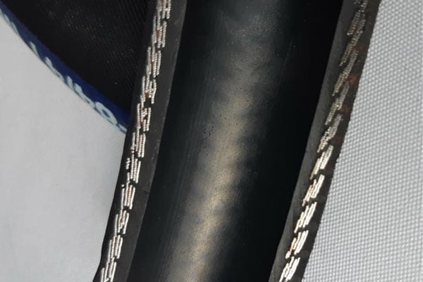
Characteristics of Wire Braid Hoses

Hoses like 1SN and 2SN have wire reinforcement that is braided together like a net around the inner tube.

Characteristics of Wire Spiral Hoses

Hoses under the EN 856 standard (like 4SP and 4SH) have layers of high-tensile wire wrapped in parallel spirals.

When to Choose Braid vs. Spiral

What Do Pressure Ratings Actually Mean?

The hose says “Max Working Pressure 40 MPa,” but you know your system sometimes spikes higher. Ignoring this number is tempting, but it can lead to a dangerous hose burst.

The stated pressure is the **Maximum Allowable Working Pressure (MAWP)**. It is the highest pressure the hose can safely and continuously operate at. Hydraulic systems are designed with a safety factor, meaning the hose’s actual burst pressure is much higher, but you must never exceed the working pressure.

Safety in hydraulics is paramount. A hose failure at high pressure can release a jet of hot oil at near-supersonic speed, capable of causing severe injury or death. The pressure rating is not a suggestion; it’s a hard limit determined through extensive testing.

Working Pressure vs. Burst Pressure

These are two different but related numbers.

The Industry Standard 4:1 Safety Factor

For most industrial and mobile hydraulics, hoses are designed with a 4:1 safety factor. This means the minimum burst pressure is four times the maximum allowable working pressure.

This safety margin accounts for minor pressure spikes, hose aging, and slight wear and tear. It is not extra capacity for you to use.

Why You Must Never Exceed Working Pressure

Operating a hose above its MAWP, even if it’s below the burst pressure, is extremely dangerous. It will drastically shorten the life of the hose by over-stressing the wire reinforcement. This leads to premature fatigue and a sudden, unexpected failure. Always select a hose with a MAWP that is equal to or greater than the maximum normal operating pressure of your system, including any common spikes.

Are There Other Important Markings on a Hose?

You’ve decoded the main P.A.S.S. elements, but there are other numbers and symbols. Ignoring them could mean you fail a safety inspection or use a hose that is too old.

Yes, many hoses include other critical data. You should look for a manufacturing date code to ensure the hose is not too old, as well as any special certifications like MSHA (for mining) or temperature ratings that are vital for specific applications.

Markings on a Hydraulic Hose

Finding the Manufacturing Date Code

Rubber has a limited shelf life. Most manufacturers print a date code on the hose, often in the format of Quarter/Year (e.g., “Q3 23” means the hose was made in the third quarter of 2023). It is good practice to avoid using hoses that are more than 5-7 years old, even if they have never been in service, as the rubber can degrade over time.

MSHA (Mine Safety and Health Administration) Certification

If a hose is intended for use in underground mining, it must have an MSHA certification printed on its layline. This marking (e.g., “MSHA IC-40/32”) indicates that the hose cover has been tested and approved as being flame-resistant, a critical safety feature to prevent fires in a mine environment. Using a non-MSHA hose in a mine is a serious safety violation.

Temperature and Fluid Compatibility Ratings

Some laylines will also include the maximum temperature rating (e.g., “100°C / 212°F”) or symbols indicating compatibility with specific fluids like phosphate esters. Always check these details if your application involves extreme temperatures or non-standard hydraulic fluids to prevent hose degradation and failure.

Conclusion

The layline on a hydraulic hose is not a secret code. It is a clear and concise data sheet designed to help you. By understanding the standard, construction, size, and pressure, you can make safe and intelligent purchasing decisions that keep your machinery running efficiently and your workplace safe.

Choose Topa hydraulic hoses for reliable performance in the toughest conditions. Our hoses meet international standards, offering excellent pressure resistance, flexibility, and long service life. Contact us today to place your order and keep your equipment running safely and efficiently.


FAQ

What is a hose layline?

A layline is the printed text on the hose that shows its standard, construction, size, and pressure rating.

Why is the layline important?

It helps you identify the correct replacement hose and avoid costly or dangerous mistakes.

How do I read hose size from the layline?

Sizes are shown as dash numbers (e.g., -08), millimeters (mm), inches (“), or DN values.

What does the pressure rating on the layline mean?

It shows the maximum safe working pressure (MAWP). The system must never exceed this value.

Can SAE and EN hoses be interchangeable?

Yes, many SAE and EN types match (e.g., SAE 100R2AT = EN 853 2SN). Always confirm specifications.

What other markings should I check on a hose?

Look for the manufacturing date code, MSHA certification, and temperature/fluid compatibility ratings.

Prevent Hose Failure with Proper Installation

How to Prevent Hose Failure with Proper Installation?

Your new hose assembly failed far too soon, causing a leak and stopping work. That unexpected downtime is expensive, and a high-pressure leak is a serious safety risk for everyone nearby.

The secret is installing the hose correctly by working with its natural properties, not against them. Proper installation respects the hose’s natural bend, uses the right fitting angles, and ensures the correct length to prevent all stress, which is the key to a long, reliable service life.

What is a Hose’s Natural Bend Direction?

You are trying to force a hose into position, but it seems to fight back. This creates hidden stress points that you can’t see, which will eventually lead to a premature leak or burst.

Every hose has a natural curve from being coiled during manufacturing and storage. This is its natural bend direction. Installing the hose along this curve eliminates internal stress and is the first step toward a long-lasting, reliable assembly.

Hydraulic hoses working

Think of it like the grain in a piece of wood. You can work with the grain for a smooth finish, or you can work against it and cause splintering. A hydraulic hose is no different. Forcing it to bend against its natural curve twists the internal wire reinforcement, creating fatigue points. Simply identifying this natural bend and using it to your advantage will significantly increase the assembly’s service life.

Why Do Hoses Have a Natural Bend?

Hydraulic hose is constructed in long, continuous lengths and then stored in large coils. This coiling process imparts a permanent, gentle curve into the hose structure. Even after it is cut and assembled, this “memory” remains. It’s not a defect; it’s an inherent property of the product. The goal of a good installation is to accommodate this property rather than fight it.

How to Identify the Natural Bend Plane

The method is very simple. Lay the hose assembly on a flat, level surface and let it rest freely. The plane it naturally lies on is its horizontal reference plane, and the curve it forms is its natural bend direction. When planning your installation route, you should aim to have the primary bend of the hose follow this natural curve.

The High Cost of Ignoring the Natural Bend

When you bend a hose against its natural curve, you are not just bending it; you are also twisting it. This torsional stress puts uneven strain on the steel wire reinforcement layers. Under pressure, the hose will try to unwind itself. This constant internal friction and stress on the wires leads to metal fatigue, which is a leading cause of premature hose failure. The hose might look fine on the outside, but it’s being destroyed from within.

How Do You Configure Bent Hose End Fittings?

You have a hose with an angled fitting, but you aren’t sure which way it should point. Guessing wrong can twist the hose, creating a hidden failure point that will cause problems later on.

To prevent twisting, you must use standard fitting configurations. These configurations define the orientation of the bent fitting in relation to the hose’s natural bend plane, ensuring a stress-free connection in any direction.

hose direction

When we manufacture a hose assembly with a bent fitting, we need to know its final orientation. This is specified using a clear and simple system. This system ensures that the hose you receive is built to be installed without any twist. Understanding these configurations is vital when ordering or installing assemblies with one or two bent ends, as it is the key to preventing torsional stress.

Assemblies with One Bent Fitting

When one end is a straight fitting and the other is a bent fitting (like a 45° or 90° elbow), there are four standard positions. These are defined relative to the hose’s natural bend plane.

Choosing one of these four standard options when ordering ensures the hose will fit perfectly without being forced.

Assemblies with Two Bent Fittings

When both ends have bent fittings, we need to know their angle relative to each other. This is called the “assembly angle” or “V-angle.” It is measured by holding the near fitting pointing straight up (this is the 0° position) and then measuring the angle to the far fitting in a clockwise direction. There are ten common standard configurations for these assemblies.

Why is the Hose Fitting Angle So Critical?

A slightly twisted hose assembly does not look like a big problem. But that small amount of twist is a silent killer, slowly destroying the hose’s reinforcement from the inside every time the system is pressurized.

The fitting angle’s only job is to prevent twisting. A twisted hose will try to unwind violently under pressure, which causes the internal wire layers to rub against each other and leads to fatigue. A correctly specified angle ensures the hose only bends in one plane, totally eliminating this destructive force.

hose angle

Bending vs. Twisting: The Key Difference

It is crucial to understand that bending and twisting are not the same.

How We Measure the Assembly Angle (V-Angle)

The V-angle is the industry standard for specifying the orientation between two bent fittings. The process is precise:

An angle of “V90” means the far fitting is at a 90-degree angle clockwise from the near one. An angle of “V180” means it is pointing in the opposite direction

Common V-Angle Configurations

How Do You Calculate the Correct Hose Length?

Your replacement hose is too short and is being pulled tight, or it’s too long and is rubbing against the machine’s frame. Both of these scenarios will cause the hose to fail very quickly.

You must calculate the correct hose length using a formula that accounts for the straight sections, the bend radius, and the fittings. For moving applications, you must also add extra length to accommodate the full range of motion. This prevents stress from tension and damage from abrasion.

Hydraulic Hose Layout wrong and right

A hose that is too short is under constant tension. This pulls on the fittings and can cause the hose to fail at the crimp. A hose that is too long will sag and rub against other components, wearing away the outer cover and exposing the reinforcement wires to damage. Taking a few moments to calculate the proper length before ordering is a simple step that prevents these common and costly failures.

Calculating Length for Fixed Installations

For a hose that connects two fixed points with a single 90-degree bend, use the following formula to find the overall length (L).

Formula: L = A + B + (π/2 * R)

Important Note: You must also add sufficient straight hose length at each end (at least 1.5 times the hose outside diameter) before the bend begins. This ensures the bend doesn’t put stress on the fitting.

Calculating Length for Dynamic Applications

When a hose is connected to a moving part, like the boom of a crane, you must account for this movement. The calculation is similar, but you must add extra length to prevent the hose from being stretched at the limits of travel.

Formula: L’ = A + B + (π/2 * R) + D

The new parameter is:

What Are the Most Common Installation Mistakes?

You installed a new hose assembly, and the machine is running fine. But a hidden routing mistake is already working to destroy that new part, guaranteeing you will be replacing it again much sooner than expected.

The most common installation mistakes are easy to avoid once you know what to look for. These include twisting the hose during tightening, bending it too sharply, poor routing that causes abrasion, and creating tension by making it too short.

Hydraulic Hose Assembly install Routing

Mistake 1: Twisting During Tightening

This often happens when tightening a JIC or other swivel fitting. The user tightens the nut but allows the hose itself to twist.

Solution: Always use two wrenches. One wrench to hold the hose and fitting steady, and a second wrench to turn only the swivel nut. This ensures all tightening force is rotational and does not translate into torsional stress on the hose.

Mistake 2: Violating the Minimum Bend Radius

Every hose has a specified minimum bend radius. Bending it sharper than this limit will cause the hose to kink. This restricts flow and puts extreme stress on the reinforcement at the outer edge of the bend, leading to a burst.

Solution: Always know the minimum bend radius of your hose and ensure your routing is well above this limit.

Mistake 3: Abrasion and Heat

Routing a hose where it can rub against a machine frame, another hose, or a sharp edge is a guarantee of failure. The abrasion will wear through the cover and compromise the wire reinforcement. Similarly, routing a hose too close to an engine exhaust or other heat source will cook the rubber, making it brittle.

Solution: Use clamps to secure hoses and maintain proper spacing. Use protective sleeves or guards in areas with high abrasion risk.

Mistake 4: Tension

A hose that is pulled perfectly straight between two points is a hose under tension. Hydraulic hoses are designed to have some slack. They can contract or expand slightly in length as they are pressurized. A taut hose has no room for this, which puts immense stress on the crimped fittings.

Solution: Always ensure there is a visible, slight sag in the hose.

How Do You Measure a Hose Assembly Properly?

You need to re-order a complex hose assembly. You measure it quickly, but when the new part arrives, it doesn’t fit because you measured from the wrong points.

You must measure a hose assembly using industry-standard reference points. For straight fittings, you measure from the end of the sealing surface. For bent fittings, you measure from the centerline of the fitting’s bore. Adhering to these standards ensures the replacement you order is an exact match.

hose measurement

Accuracy is everything when ordering a replacement. As a manufacturer, we build parts to the precise length and tolerance requested by our customers. Using the correct measurement technique eliminates errors and ensures you get the right part on the first try, saving you time and the cost of shipping returns. It’s about speaking the same language as your supplier.

Standard Measurement Points

Understanding Standard Length Tolerances

No manufacturing process is perfect, so there are acceptable tolerances for hose assembly lengths. These tolerances vary based on the length of the hose.

Knowing these tolerances helps you understand the acceptable range for a new part and allows you to check if a supplied product meets quality standards.

Conclusion

Proper installation is not complicated. By respecting the hose’s natural bend, calculating the right length, using the correct fitting angle, and routing it carefully, you can guarantee a longer, safer service life for every hydraulic hose assembly you install.

Choose Topa for reliable hydraulic fittings, hoses, and couplings. Our products are built to international standards, offering durability, precision, and fast delivery. Contact us today to place your order and keep your equipment running at peak performance.


FAQ

How can I tell if a hose has been twisted during installation?

If the hose shows a spiral mark along its cover or resists natural movement when pressurized, it has likely been twisted.

What happens if a hose is too short for the installation?

A short hose creates constant tension, pulling on the fittings and increasing the risk of leaks or burst failures.

Why do hose assemblies sometimes fail even when the fittings are tight?

Failures often come from hidden issues such as twisting, over-bending, or abrasion—not just loose fittings.

Can protective sleeves really extend hose life?

Yes. Sleeves protect against abrasion, UV, and heat, helping the hose last much longer in harsh environments.

Do hydraulic hoses need slack in every installation?

Yes. A small amount of slack allows the hose to expand and contract under pressure without stressing the fittings.

What is the most reliable way to measure a hose assembly for replacement?

Always measure from the sealing surfaces of the fittings (straight or bent) according to industry standards to avoid errors.

How to Identify Metric, American, and Pipe Threads Fast

How to Identify Metric, American, and Pipe Threads Fast?

You’re holding a hydraulic fitting with “UNF” threads and need to connect it to a port marked “G”. They look similar, but they won’t go together. Using the wrong thread can cause leaks, damage expensive equipment, and lead to critical failures.

You can identify any thread by checking two key features: its thread angle (usually 60° or 55°) and its shape (parallel or tapered). This guide and our cheat sheet at the end will teach you how to spot these differences instantly.

Why Do Thread Standards Even Matter?

You might think a thread is just a thread. But using the wrong tap in a machine shop or forcing two different thread types together can lead to a low-level mistake with irreversible and costly consequences.

Threads are the foundation of the mechanical world, holding everything from watches to spacecraft together. Using the correct, standardized thread ensures a strong, reliable, and leak-proof connection. Getting it wrong is a direct path to system failure.

Hydraulic plug working principle

The Foundation of Safe Mechanical Assembly

Standardization ensures that components are interchangeable, strong, and predictable. When you use an M8 bolt, you know its exact dimensions, its strength characteristics, and how it will behave under load. This predictability is the basis of all safe and reliable mechanical design. Without it, every single component would have to be a custom one-off part.

The High Cost of a Thread Mismatch

Forcing incompatible threads together is called “cross-threading.” It permanently damages both the male and female threads, a process known as galling. This often makes the parts unusable. In a plumbing or hydraulic system, even a slight mismatch will create a leak path. This can lead to fluid loss, equipment damage, environmental contamination, and serious safety hazards.

What Are the Metric Thread Standards?

You see an “M8” bolt. You know it’s metric, but what does that really tell you? Not knowing the difference between a standard coarse thread and a fine thread can lead you to choose the wrong fastener for a critical application.

The “M” stands for Metric, the most common thread system in the world. The number indicates the nominal diameter in millimeters. Metric threads have a 60° thread angle and are the default choice for general mechanical connections globally, outside of North America.

DIN 7631 Metric Thread

The metric system is wonderfully logical. Its design is based on simple, easy-to-understand units. When you are sourcing parts for machinery made in Europe or Asia, you will almost certainly be dealing with metric threads.

The Global Standard: M Threads

The ‘M’ profile thread is the international standard for general-purpose screw threads. Its 60° symmetrical V-shape is excellent for fastening and provides good strength. The specification is simple: the nominal diameter followed by the pitch (the distance between threads). For example, “M8 x 1.25” means an 8mm diameter with a 1.25mm pitch.

Coarse vs. Fine Threads

Special Metric Threads: MJ for Aerospace

The MJ thread is a modification of the standard metric thread, designed for the extreme safety requirements of the aerospace industry. It features a larger root radius in the thread profile. This rounded root distributes stress more effectively, dramatically increasing fatigue strength and reducing the risk of a crack forming under a heavy load.

How Do You Read Unified (American) Threads?

Your hardware is from the USA, and the bolts are marked UNC and UNF. They look very similar, but they serve very different purposes. Using a UNC bolt where a UNF is specified could lead to disaster in a high-vibration environment.

This is the Unified Thread Standard (UTS), the American counterpart to the metric system. It also uses a 60° thread angle but sizes are based on inches. UNC means “Unified Coarse,” and UNF means “Unified Fine.” They offer different strengths and weaknesses.

UNF and UNC

The UTS system dominates in North America. Learning to read these standards is essential for anyone working with American-made equipment. The core concept is the same as metric threads: coarse threads for general use and fast assembly, and fine threads for precision, strength, and vibration resistance. The choice between UNC and UNF is a critical engineering decision based on the application’s specific demands.

Unified Thread Series (UNS)

The Unified Thread Series, commonly used in the United States and many international industries, includes three major families: UNC, UNF, and UNEF. Each type has unique characteristics tailored to different performance requirements.

UNC – Unified National Coarse Thread

Characteristics: Coarse-pitch design with larger thread spacing and deeper thread depth.

Advantages:

Applications: The most common general-purpose thread form, widely used in structural steelwork, construction fasteners, and standard bolts and nuts.

UNF – Unified National Fine Thread

Characteristics: Fine-pitch design with smaller thread spacing and shallower thread depth.

Advantages:

Applications: Commonly used in aerospace components, automotive engines, and precision instruments where reliability and accuracy are critical.

UNEF – Unified National Extra Fine Thread

Characteristics: Even finer pitch than UNF, with extremely close thread spacing.

Advantages:

Applications: Specialized uses such as instrumentation, electronic equipment, and applications requiring fine mechanical alignment.

What’s the Difference Between All the Pipe Threads?

This is a major source of confusion. You have an NPT fitting, a G fitting, and an R fitting. They are all pipe threads, but none of them will seal with each other. This mistake can cause persistent, damaging leaks.

The key differences are the thread angle and the **shape**. American NPT threads are tapered with a 60° angle. British/ISO pipe threads (G, R, Rc, Rp) are based on a 55° angle. Furthermore, G is parallel, while NPT and R are tapered.

NPT vs BSPT Taper Threads

Pipe threads are designed to create a pressure-tight seal for carrying fluids or gases. Unlike mechanical threads that just fasten, these must prevent leaks. The world is divided into two main camps for pipe threads, and they are completely incompatible. Knowing which camp you are in is the first and most important step to creating a leak-free system.

American Standard: NPT & NPTF (60° Taper)

NPT (National Pipe Taper): This is the North American standard. It has a 60° thread angle and a 1:16 taper. The seal is created by the threads deforming into each other as they are tightened. A sealant (like PTFE tape or pipe dope) is required to fill any gaps.

NPTF (National Pipe Taper Fuel): Also called “Dryseal,” this thread is dimensionally similar to NPT but has controlled crests and roots. This ensures a metal-on-metal seal without the need for sealant, making it ideal for fuel and hydraulic systems where sealant could contaminate the fluid.

British/ISO Standard: G (55° Parallel)

G (BSPP – British StandardPipe Parallel): This thread has a 55° angle and is parallel (straight). The threads themselves do not form a seal. The seal is made by a gasket, O-ring, or bonded washer that is compressed against the face of the fitting. This is the common standard in Europe, Asia, and most of the world for hydraulics and plumbing.

British/ISO Standard: R, Rp, Rc (55° Taper)

R/Rc/Rp (BSPT – British StandardPipe Taper): This is the tapered counterpart to the G thread. It also has a 55° angle.

R refers to the external tapered thread.

Rc (Tapered) and Rp (Parallel) refer to the internal threads.

A male R thread can seal with a female Rc or Rp thread. Like NPT, a sealant is required.

How Do I Choose the Right Thread?

You have a port to fill. How do you decide between NPT, G, or UNF? Making the wrong choice means you will be ordering parts all over again, wasting time and money.

First, determine the application: are you fastening or sealing? Then, identify the system’s origin to choose the right standard (American vs. European/ISO). Finally, focus on key identifiers like the 55° vs. 60° thread angle to confirm your choice.

Metric Sealing Methods

Choosing the right thread is a process of elimination. As a manufacturer, we use this same logic when helping our customers. By asking these simple questions, you can quickly narrow down the possibilities from dozens to just one or two. To make it even easier, we’ve compiled all the essential information into one simple chart.

Step 1: Connecting vs. Sealing

Step 2: Use the Ultimate Litmus Test: 55° vs. 60°

This is the most critical check. Get a thread gauge.

These two systems are never compatible. This single test can prevent the most common and damaging mistakes.

Your Ultimate Thread Identification Chart

Use this table as your quick reference guide. It contains all the core information you need to identify almost any thread you will encounter in the field.

Conclusion

The world of threads is vast, but it is not complicated. By understanding the core families and their key features like thread angle and shape, you can confidently identify and select the correct thread for any job, ensuring a safe and reliable system.

Choose Topa’s precision-engineered hydraulic fittings for your business needs. Our products are built to international standards, ensuring reliable performance, long service life, and cost savings. Contact us today to place your order and keep your equipment running safely and efficiently.


FAQ

Can I use thread sealant on fittings that are designed for metal-to-metal sealing (like NPTF)?

While not required, adding sealant on NPTF can actually prevent proper sealing by interfering with the controlled crest and root engagement..

How can I quickly tell if a thread is parallel or tapered without special tools?

Place the fitting against a straight ruler or caliper. If the thread flanks gradually narrow, it’s tapered (NPT, BSPT). If they remain constant, it’s parallel (UNF, G/BSPP, Metric).

Are metric and UNF threads interchangeable since both have a 60° angle?

No. Even though both use a 60° angle, the pitch, diameter, and tolerances differ. Attempting to mix them causes cross-threading and damage.

Why do British threads use a 55° angle instead of 60°?

The 55° Whitworth form is an older British standard. It provides slightly more thread engagement but is not compatible with 60° metric or unified forms.

What’s the safest way to identify an unknown thread in the field?

Use a thread gauge and caliper to measure pitch, diameter, and angle. Then compare results with a reference chart. This avoids costly assumptions.

Can pipe threads (like NPT and BSPT) ever be safely joined with adapters?

Yes, but only with specialized conversion adapters that correctly match the sealing method. Directly mating NPT with BSPT will almost always leak.

How to Install Reusable Hydraulic Fittings in the Field

How to Install Reusable Hydraulic Fittings in the Field?

Your machine is down with a blown hose, miles from a workshop. Without a crimper, you’re stuck, losing valuable time and money with each passing minute of downtime.

You can fix a hose anywhere using only basic hand tools with reusable hydraulic fittings. The secret is correctly assembling the two-piece fitting—the socket and the nipple—onto a properly cut hose for a secure, factory-quality repair that gets you running again fast.

Why Choose Reusable Fittings for Field Repairs?

You need a new hose *now*, but the nearest hydraulic shop is hours away. Waiting for a mobile repair van is expensive, and carrying a heavy crimper everywhere is simply not practical for most operators.

Reusable fittings solve this problem entirely. They are specifically designed for assembly using only common hand tools, like a wrench and a vise. This turns a major delay into a minor, on-the-spot repair you can perform yourself.

install Reusable hose fitting

Think of reusable fittings as your hydraulic first-aid kit. While permanently crimped fittings are excellent for mass production and standard assemblies, reusable fittings provide unmatched value for emergency repairs, prototyping, and low-volume custom applications. Their genius lies in a simple, robust mechanical design that allows for secure attachment without any specialized hydraulic equipment. Understanding this difference is key to appreciating why they are so valuable for field service.

Understanding the Two-Piece Design

Unlike a one-piece crimp fitting, a reusable fitting consists of two separate, precision-machined components:

When Are Reusable Fittings the Best Choice?

Reusable fittings are the superior option in several common scenarios. Keeping a stock of common sizes can be a business-saving decision for many operators. They are ideal for:

What Tools Are Essential for a Field Repair?

You have the reusable fitting, but you’re missing a key tool. Now you are stuck trying to improvise, which risks a bad assembly, a persistent leak, or personal injury.

A successful field repair depends on having a small but specific set of tools ready. A proper hose cut and clean assembly are impossible without them. Prepare a simple kit with the right tools before you need it.

Fieldattachable fittings Install Tools

Essential Cutting and Preparation Tools

Getting the hose end prepared correctly is half the battle. A clean, square cut is non-negotiable for a leak-free seal.

Assembly and Tightening Tools

Proper assembly requires leverage and lubrication.

Safety First: Personal Protective Equipment (PPE)

Working with hydraulic hoses involves sharp wire and high pressures. Never attempt a repair without the proper safety gear.

How Do You Safely Remove an Old Fitting?

You need to reuse the fitting, but you damage the threads while trying to remove it from the old, failed hose. Now the expensive reusable fitting is just as useless as the broken hose.

To safely remove and inspect a reusable fitting, you must use a systematic process. Secure the hose in a vise and use two wrenches to carefully unscrew the components without applying twisting force to the hose itself.

broken Reusable fitting

The whole point of these fittings is their reusability. A careless removal process can easily ruin them, defeating their purpose. Taking a moment to disassemble the fitting correctly not only salvages the component but also gives you a chance to inspect it for wear and tear. A damaged fitting should never be reused, as it will compromise the integrity of your new repair.

Step 1: Secure the Hose in a Vise

Firmly clamp the hose in a bench vise, allowing about 6 inches (15 cm) to stick out with the fitting attached. Clamp on the hose, not the fitting socket. This provides the stability needed for the next steps.

Step 2: Loosen and Unscrew the Nipple and Socket

First, use one wrench on the socket hex and another on the nipple hex to break the connection loose. Unscrew the nipple completely and remove it. Next, place a wrench on the socket hex and turn it clockwise to unscrew it from the hose. This is because the socket has a left-hand thread. It screws onto the hose counter-clockwise and comes off clockwise.

Step 3: Inspect Components for Reuse

Once removed, clean the socket and nipple thoroughly and inspect them for any signs of damage. This is a critical safety step.

Only reuse fittings that are in perfect condition. When in doubt, throw it out. The cost of a new fitting is nothing compared to the cost of a failed assembly.

What is the Correct Assembly Procedure?

You assembled your new hose, but it leaks from the fitting as soon as you power up the system. A subtle mistake during assembly has created a leak path, and now you have to do the job all over again.

To guarantee a leak-proof seal, you must follow the correct assembly sequence precisely. This involves a square cut, proper lubrication, and screwing the socket and nipple together to the correct depth.

install reusable Hydraulic Fitting

Assembling a reusable fitting is a skill. It’s not difficult, but it requires attention to detail. Each step builds on the last to create a strong, reliable connection. Skipping a step or taking a shortcut, like forgetting to lubricate the threads, is the number one cause of field assembly failures.

Step 1: Prepare the Hose End

Measure your replacement hose and make a clean, square cut. An angled cut will prevent the hose from seating properly against the nipple and will cause a leak. Use a utility knife to trim away any frayed rubber or loose wire from the hose end.

Step 2: Screw the Socket onto the Hose

Clamp the hose in the vise. Lubricate the hose end and the internal threads of the socket. Now, push the socket onto the hose and turn it counter-clockwise to screw it on. The socket has a left-hand thread. Continue screwing until the hose just bottoms out inside the socket, then back it off a quarter turn.

Step 3: Lubricate and Insert the Nipple

Liberally lubricate the threads of the nipple and the inside of the hose. Push the nipple into the socket and hose end until you can engage the threads by hand.

Step 4: Tighten the Nipple into the Socket

Use two wrenches—one to hold the socket steady and one to turn the nipple hex. Tighten the nipple into the socket **clockwise**. Continue tightening until there is a small, visible gap between the nipple hex and the socket. Do not tighten until they touch. This gap is intentional and confirms a correct assembly. The size of this gap is typically 1/16 to 1/32 of an inch (0.8mm to 1.5mm).

What Common Mistakes Cause Leaks and Failures?

Your field repair failed almost immediately. You’re frustrated and covered in hydraulic oil. An easily avoidable mistake during assembly has cost you more time and created a bigger mess.

The most common mistakes are simple but critical: an angled hose cut, forgetting lubrication, incorrect socket depth, and over-tightening the nipple. Avoiding these four pitfalls is the key to a successful, long-lasting repair.

reusable Hydraulic Hose Assemblies

We have analyzed countless failed field assemblies over the years. The cause is almost never a defective fitting. It is overwhelmingly due to a simple error in the assembly process. Understanding these common mistakes is the most effective way to ensure your repairs are done right the first time, every time. Think of this as the professional technician’s checklist of what not to do.

Mistake #1: A Bad Hose Cut

A cut that is not perfectly square to the hose’s centerline is the number one cause of leaks. An angled cut means the hose end will not sit flush against the bottom of the nipple. This creates a direct leak path that no amount of tightening can fix.

Mistake #2: Forgetting Lubrication

Assembling the fitting dry will cause the threads to gall and bind. This gives you a false sense of tightness. You may think the fitting is fully assembled, but it is not. The friction from the dry threads has stopped you from achieving the proper compression.

Mistake #3: Incorrect Socket Position

If you don’t screw the socket onto the hose far enough, the nipple won’t be able to properly expand the hose tube for a good seal. If you screw it on too far, it can be difficult to start the nipple threads.

Mistake #4: Over-tightening the Nipple

Many people think tighter is better. With reusable fittings, this is false. Tightening the nipple until it touches the socket can damage the internal threads, strip the fitting, or cut the hose’s inner tube, creating a failure point.

Conclusion

Mastering reusable fittings gives you the power to make reliable hydraulic repairs anywhere. You can turn costly downtime into a quick, simple fix with only the basic tools you already have, giving you control over your maintenance schedule.

Keep your machines running anywhere, anytime with Topa reusable hydraulic fittings. Designed for quick field repairs using only hand tools, they save you costly downtime and ensure reliable, leak-free performance. Contact us today to place your order and secure fittings that deliver strength, flexibility, and true peace of mind.


FAQ

What makes a fitting “reusable”?

Reusable fittings can be disassembled and reattached to a new hose using only hand tools, unlike crimp fittings which are permanent.

Do I need special tools to install reusable fittings?

No. A vise, two wrenches, a hose cutter (or hacksaw), and lubrication are enough for proper assembly.

Can reusable fittings handle the same pressure as crimp fittings?

Yes, when correctly assembled, they meet the same pressure ratings as equivalent crimped fittings.

What are the most common mistakes during assembly?

Bad hose cuts, forgetting lubrication, incorrect socket depth, and over-tightening the nipple.

When should I choose reusable fittings over crimp fittings?

They are best for emergency field repairs, remote locations, prototyping, and low-volume custom hoses.

Can I reuse a fitting from an old hose?

Yes, but only if it passes inspection. Discard any fitting with damaged threads, cracks, or worn sealing surfaces.

Contact Topa

Save 30% on maintenance costs with our easy-install hydraulic fittings. Contact Now!