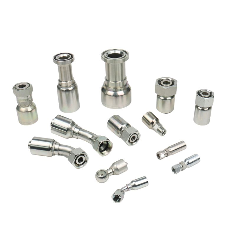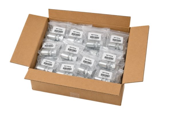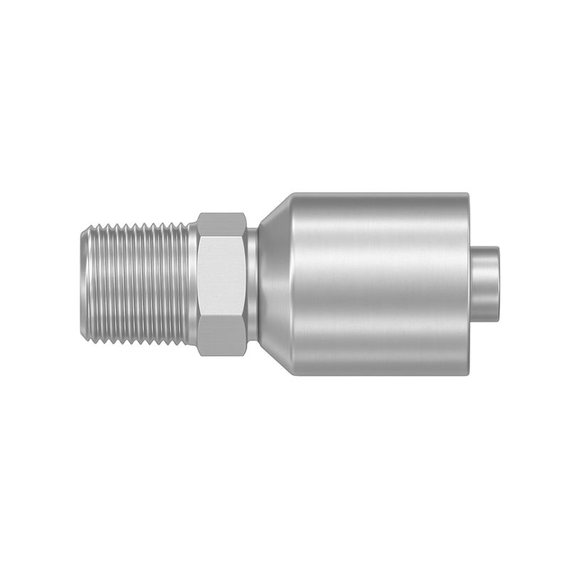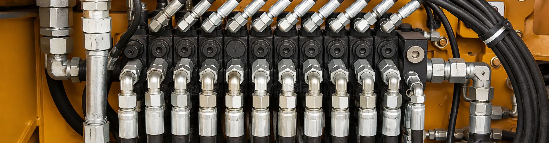
One Piece Fitting Emergency Stock

One Piece Fitting Emergency Stock: What to Prioritize

One-piece fitting emergency stock should first cover verified combinations tied to critical equipment, recurring failures, supported hose inventory, and the available crimp process. It should not begin with the largest assortment or the most familiar thread sizes. A fitting helps during an emergency only when its connection standard, port dash, hose dash, fitting series, geometry, and assembly data match the failed position. Prioritization therefore combines Equipment Criticality, Failure Frequency, Downtime Consequence, Existing Hose Inventory, Available Crimp Equipment, Lead Time, and Substitution Risk.

Emergency Stock Must Create Repair Capability

The purpose of emergency inventory is to shorten the time from a verified failure to a safe, supportable hose assembly. Physical pieces on a shelf are not the same as repair capability.

hydraulic fitting packing stock Topa

Count only fittings that can become approved assemblies

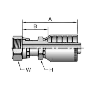
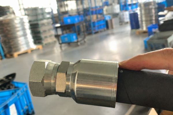
A one-piece fitting has its body or stem and ferrule preassembled, attached, or retained together, but exact construction varies by series. That arrangement may reduce separate ferrule picking; it does not prove compatibility with a hose or crimper. Usable emergency stock needs a known hose manufacturer and series, hose construction and dash, Verified Fitting Series, preparation method, Available Crimp Equipment, die set, current crimp specification, and defined finished-assembly checks.

This boundary explains why more inventory does not automatically create stronger emergency response. Mixed bins, uncertain series, obsolete finishes, or fittings unsupported by the local hose and crimp system can increase search time and false confidence. Exclude damaged, unidentified, or technically unsupported pieces from the usable count until they are resolved.

Define the emergency before ranking parts

An emergency is not simply any request marked urgent. Define which equipment functions create an immediate production, safety, environmental, or service consequence when a hose fails and which assets have redundancy or a planned alternative. Also identify who can isolate the system, confirm the fitting, build the assembly, and approve return to service. Stock without this operating path may move a fitting faster while leaving the repair decision incomplete.

The response must never bypass safety. Stop the equipment, isolate the hydraulic circuit, release pressure and stored energy, secure raised or suspended loads, follow lockout requirements, and use the equipment and component manufacturers’ procedures. Never check suspected pinhole leakage by hand, remove a pressurized fitting, or install a near match because downtime is accumulating.

Rank Equipment Criticality and Failure Frequency Separately

Equipment Criticality shows how serious a stoppage is; Failure Frequency shows how often a verified fitting need occurs. Keeping the factors separate prevents frequent low-impact repairs from crowding out rare but consequential failures.

Evaluate Downtime Consequence and redundancy

For each machine or hydraulic function, record what stops when it fails, whether a safe redundant asset or process exists, and whether the repair can be scheduled. Downtime Consequence may include an entire line stopping, a mobile service unit becoming unavailable, or a critical attachment being unable to complete its work. Do not invent a universal downtime cost or service target; use the organization’s verified operating evidence.

Criticality alone does not justify stocking an uncertain item. The connection, hose side, geometry, and assembly method must be verified before an SKU becomes emergency coverage. If the application is critical but the fitting identity remains unresolved, the correct action is to complete technical identification and establish a controlled sourcing plan, not to place an ambiguous part in the core bin.

Separate repeat failures from repeat consumption

Failure Frequency should come from confirmed repair records, not purchase totals alone. Repeated purchases can reflect wrong picks, duplicate orders, routing damage, contamination, or a fitting series that was never approved. A useful record ties the issued fitting to equipment, position, failure cause, Connection Standard, Port Dash, Hose Dash, configuration, hose and fitting series, and successful assembly verification.

Review repeated failures for root causes before normalizing them as stock demand. Abrasion, movement, heat, inadequate bend allowance, installation twist, or external impact may continue consuming fittings even when inventory is full. Emergency stock reduces supply delay; it cannot correct the condition causing the hose assembly to fail.

Match Stock to Existing Hose and Crimp Capability

Existing Hose Inventory and Available Crimp Equipment determine which fitting combinations a repair team can actually use. A thread match at the port is insufficient when the hose tail is unsupported.

Verify the hose and fitting series as one system

Record the exact hose manufacturer, hose series, construction, reinforcement, Hose Dash, and relevant outside-diameter information required by the controlled procedure. Then link that hose to the Verified Fitting Series and ferrule design. Equal dash size is only a nominal size relationship; it does not prove that two hose constructions accept the same stem, ferrule compression, preparation, or crimp dimension.

Emergency bins should not mix fittings from different series under a generic hose-size label. Use part identity and controlled compatibility records that the assembly operator can retrieve quickly. When the repair shop changes hose series, fitting series, or suppliers, revalidate the affected inventory rather than assuming the previous emergency matrix still applies.
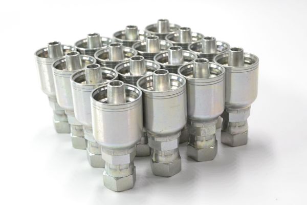
order of one piece Fitting

Confirm the process, tools, and current data

Available Crimp Equipment includes more than the machine name. Confirm that the correct die set, machine capacity, calibration or maintenance status, preparation tools, measuring equipment, and current manufacturer crimp data are accessible to the person doing the work. A fitting that requires unavailable tooling or an unverified procedure belongs outside immediate emergency capability.

Before considering an SKU usable, confirm:

Build Complete Connection, Dash, and Geometry Combinations

Emergency selection works at the combination level: connection standard plus Port Dash, Hose Dash, fitting series, and physical configuration. Omitting any one of these attributes creates stock that may fit only part of the repair.

Keep the port and hose sides distinct

Connection Standard should include the features needed to distinguish JIC, ORB, NPT, NPTF, BSPP, BSPT, Metric, ORFS, or another system used locally. Confirm gender, diameter, pitch or TPI, straight or tapered form, seat, sealing face, and O-ring location as applicable. Port Dash identifies the connection side; Hose Dash identifies the hose side, and the two values cannot be assumed to match.

Do not use a photo, old number, or apparent engagement as final acceptance. Similar threads and sealing forms can be confused, while a correct thread on the wrong seal can still leak. Thread sealant cannot correct a wrong standard, seat, taper, pitch, damaged thread, or cross-threading.

Plan Straight versus Elbow Demand from real positions

Straight versus Elbow Demand must be based on verified installation positions. Stocking only straight fittings may leave no usable repair when a 45-degree or 90-degree end is needed to clear a frame, valve, tire, articulation point, or neighboring hose. Forcing a straight end into that position can create an immediate bend, hose twist, abrasion, side loading, or interference during movement.

Elbow coverage also needs orientation information. Two assemblies with the same port and hose dash may require different angles or relative orientation to route correctly. Record configuration, swivel behavior where applicable, clearance, bend direction, and movement envelope instead of treating all elbows as interchangeable.

Use Lead Time and Substitution Risk to Set Priority

Lead Time and Substitution Risk modify priority after technical need has been established. Long supply exposure can strengthen the case for coverage, but it cannot turn an uncertain fitting into a safe substitute.

Apply a practical ranking model

Use the table as a decision record, not a numerical scoring formula. A high-frequency item for noncritical equipment may belong in planned replenishment, while a lower-frequency verified item with severe Downtime Consequence and long Lead Time may justify Backup Stock. The decision should remain explainable from current evidence.

Treat substitution as a technical review

Substitution Risk is high when candidate fittings have similar appearance but uncertain thread, sealing, hose compatibility, material, geometry, or crimp data. A replacement part number or cross-reference is useful only as a lead for verification. Final approval still requires the complete connection and assembly requirements to match.

Where a validated alternative exists, record its scope and limitations rather than assuming universal interchangeability. Where no safe substitute exists, document the supply route, technical information required for ordering, and escalation owner. This prepares the response without encouraging improvised installation.

Separate Four Inventory Classes

Four classes prevent emergency items, routine demand, and rare technical parts from competing under one label. Classification controls attention and replenishment; it does not prescribe a fixed quantity.

Define each class by purpose

An item should move between classes when equipment, repair history, hose inventory, crimp capability, lead time, or validated alternatives change. Emergency Core Stock should not become ordinary issue stock without review, and Planned Replenishment Stock should not be described as emergency coverage merely because it is physically nearby.

Keep classification and quantity decisions separate

First decide whether the fitting is technically usable and which class reflects its purpose. Only then consider quantity using verified consumption timing, replenishment behavior, current usable stock, shelf condition, and operating exposure. This order prevents a purchasing minimum or discounted pack from defining the emergency strategy.

Review open orders and duplicate locations before replenishment. Excess emergency stock can create obsolescence, mixed series, damaged threads, lost traceability, and slower picking. A smaller, clearly identified matrix backed by hose and crimp data often provides more real capability than shelves filled with uncertain near matches.

Control Common Errors With a Priority Checklist

The most damaging errors are treating all urgency as equal, ranking by frequency alone, and counting unsupported pieces as available. A concise review should expose those gaps before a failure occurs.

Verify the complete emergency record

For every proposed item, document:

Conclusion

Emergency readiness comes from verified repair combinations, not the number of fittings on a shelf. Rank needs through Equipment Criticality, Failure Frequency, Downtime Consequence, Existing Hose Inventory, Available Crimp Equipment, and the exact fitting series. Complete each candidate with Connection Standard, Port Dash, Hose Dash, straight or elbow geometry, current crimp data, Lead Time, and Substitution Risk. Then separate Emergency Core Stock, Backup Stock, Planned Replenishment Stock, and Special-Order Items so routine consumption does not hide critical exposure. Remove mixed, damaged, unidentified, and unsupported pieces from usable availability. A disciplined one-piece fitting emergency stock plan reduces identification and supply delay while preserving the thread, seal, hose, routing, and assembly controls required for a safe repair.

Frequently Asked Questions

Should every fitting used on critical equipment be Emergency Core Stock?

No, criticality is only one factor. The fitting identity, likelihood of urgent need, supported hose and crimp process, lead time, and available recovery options must also justify immediate coverage.

Can mobile repair inventory use the same priorities as a central workshop?

Not automatically, because vehicle space, service territory, equipment mix, and access to crimp equipment differ. Apply the same decision factors but classify only combinations the mobile operation can identify and assemble correctly.

How should an emergency fitting with an expired or superseded crimp document be handled?

Remove it from usable emergency status until current controlled data confirms the combination. A familiar historical procedure is not a substitute for an applicable current specification.

Does a short supplier lead time eliminate the need for Backup Stock?

Not necessarily, because actual availability, operating hours, transport constraints, and Substitution Risk may still leave exposure. Use verified replenishment performance rather than a quoted lead time alone.

Can a reusable fitting replace a stocked one-piece fitting during an emergency?

Only if the reusable system is specifically approved for the hose and application and its installation procedure is followed. The different construction should not be treated as an automatic or temporary substitute.
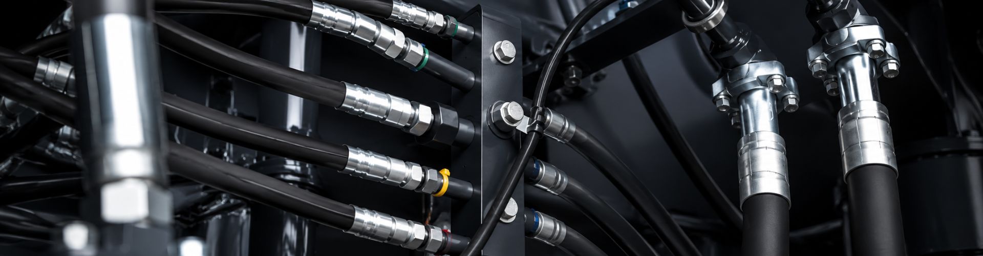
One Piece Fitting Crimp Dimensions What to Confirm

One Piece Fitting Crimp Dimensions: What to Confirm

One piece fitting crimp dimensions are controlled data for a complete hose assembly, not universal values attached to a fitting or dash size. The required result depends on the Hose Manufacturer, Hose Series, Hose Construction, Hose Dash, Fitting Series, Stem Geometry, Ferrule Design, Crimping Machine, Die Set, preparation, and Current Manufacturer Crimp Data. Copying a diameter from a similar assembly can leave the hose incorrectly compressed or the stem improperly retained even when the finished ferrule looks acceptable.

Crimp Dimensions Belong to a Verified Assembly Combination

Crimp data is valid only within the combination and procedure for which it was issued. A one-piece design reduces separate ferrule selection, but it does not remove the need to identify every component and process variable.

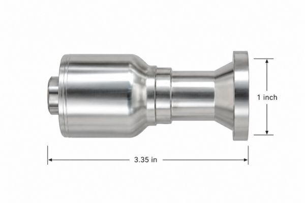
1 inch crimp flange

Treat the fitting as one part of the data set

In a one-piece fitting, the fitting body or stem and ferrule are preassembled, attached, or retained together; the exact construction varies by series. The stem supports and engages the hose internally while the ferrule is compressed around the hose structure. Stem serration, engagement area, ferrule thickness, ferrule profile, and the relationship between those parts affect how compression is transferred through the hose, so a visually similar fitting may require different controlled instructions.

The crimp record must identify the Hose Manufacturer, Hose Series, Hose Construction, Hose Dash, Fitting Series, Stem Geometry, and Ferrule Design. It must also identify the Crimping Machine, Die Set, machine setup, preparation method, and the Current Manufacturer Crimp Data being followed. If any identity is missing, an isolated final-diameter value cannot make the process complete.

Equal dash size does not create equivalence

Hose Dash is a nominal size designation; it does not define reinforcement, wall structure, cover thickness, Hose OD Before Crimping, or material response to compression. Two hoses with the same dash may belong to different series or manufacturers and may have different constructions. They therefore cannot be assumed to use the same fitting series, ferrule, preparation, dies, or final dimensions.

The same limitation applies to fittings. Two one-piece fittings may share a hose dash and similar end connection while using different stems or ferrules. Never transfer data because the components fit together by hand, appear alike in a photograph, or produced a similar measurement in an earlier job.

Distinguish Every Dimension and Preparation Variable

The phrase “crimp dimension” hides several separate controls. Each describes a different part of component preparation, tooling, deformation, or inspection and must be read in the context of the applicable procedure.

Use precise terms in the work instruction

Final Crimp Diameter and Crimp Length should never be collapsed into one acceptance statement. Diameter is a radial result; length defines the axial zone over which the dies have acted. Both require the measurement locations, instrument method, and acceptance criteria stated in the controlled data. Measuring elsewhere on the ferrule can produce a value that looks plausible but is not comparable with the specification.

Keep insertion, ferrule position, and preparation visible

Insertion Position describes how far the prepared hose reaches the designated reference on the fitting. Ferrule Position describes where the ferrule sits relative to the stem and hose before the dies close. These controls affect engagement but may be partly or completely hidden after crimping, so marking, stop features, observation windows, or other procedure-defined methods must be checked at the correct stage.

Skive or No-Skive Preparation is also combination-specific. Do not assume every one-piece fitting is no-skive or that a familiar hose needs the same cover removal with another series. Follow the current hose, fitting, and equipment instructions for cutting, skiving where required, cleaning, insertion, and positioning; never improvise a removal length or preparation method.

Confirm the Data Package Before Preparing the Hose

Pre-crimp control begins before the hose is cut or the die is installed. The operator needs a traceable data package that resolves component identity, application suitability, and the exact procedure revision.

Verify hose, fitting, and application identity

Read the hose layline and controlled stock record to confirm manufacturer, series, construction, reinforcement, Hose Dash, and any required batch or date traceability. Inspect the hose for storage damage, contamination, deformation, corrosion transfer, or other conditions that may invalidate assembly. Confirm that the Fitting Series and Ferrule Design are approved for that exact hose, not merely for a hose with the same nominal size.

The assembly must also suit the application. Working pressure is limited by the lowest-rated component and can be affected by pressure impulse, temperature, fluid, bend radius, routing, vibration, corrosion, and assembly quality. Crimp dimensions prove neither system pressure suitability nor chemical compatibility, so those requirements need separate confirmation before assembly approval.

1JS78 hydraulic crimp fittings drawing Topa

Control the document and equipment revision

Use Current Manufacturer Crimp Data applicable to the hose, fitting, and crimping system. A printed chart, saved screenshot, or prior job record may have been superseded; check its identity and revision through the organization’s controlled-document process. If the combination is absent, do not establish a value through unauthorized trial crimping.

Confirm the Crimping Machine and Die Set named or permitted by the procedure, together with required tooling, setup, calibration or maintenance status, measuring instruments, and operator instructions. A die that appears close, fits the ferrule, or was used on another series is not a verified selection. Machine and tooling differences can affect closure, die profile, crimp location, and repeatability.

Pre-Crimp Checks Protect Hidden Assembly Conditions

Many decisive conditions become difficult to see after the ferrule is compressed. The pre-crimp stage should therefore verify identity, preparation, cleanliness, insertion, and position before the assembly enters the machine.

Inspect and prepare without improvisation

Cut the hose using the method required for the hose construction and inspect the cut for deformation or reinforcement damage. Perform Skive or No-Skive Preparation exactly as the controlled procedure states, and remove debris that could enter the hydraulic system. Do not reuse a damaged fitting, ferrule, or hose section, and do not modify a stem or ferrule to make an uncertain combination fit.

Record Hose OD Before Crimping when the current procedure or quality plan requires it. This measurement may help detect an incorrect hose, storage deformation, production variation, or preparation error, but it is not itself an approval of compatibility. Use the defined instrument, location, and method rather than comparing an informal caliper reading with another assembly.

Establish insertion and ferrule position

Lubricate only when and as the controlled assembly instructions permit, because lubricant type and application can affect insertion and contamination control. Insert the fitting using the specified method and confirm Insertion Position through the designated mark, stop, inspection feature, or other defined evidence. Do not estimate insertion from the amount of stem still visible.

Before crimping, confirm Ferrule Position and the assembly’s axial alignment. The hose should not be twisted or cocked in a way that changes how the ferrule enters the dies. Where an elbow or orientation requirement exists, verify that handling and positioning will not disturb the intended assembly geometry.

Pre-crimp release should cover:

In-Process Control Requires More Than Closing the Dies

The crimping stage must reproduce the controlled setup and place the compression zone where the procedure requires it. Operator familiarity cannot replace verification of the current machine, die, and settings.

Crimping hose process

Set and position the approved tooling

Install the specified Die Set and confirm that segments are clean, undamaged, and correctly seated. Set the Crimping Machine according to the applicable instructions and verify any required machine reference or setup check. If the equipment cannot achieve or control the procedure as intended, stop rather than compensating with an improvised die, repeated compression, or an unapproved setting change.

Position the ferrule so the dies act on the specified zone and produce the required Crimp Length. Maintain alignment during closure and keep hands clear of moving tooling. Do not assume the machine’s displayed setting equals the finished diameter; the finished part must be measured by the required method.

Respond to abnormal behavior before release

Stop the process if the ferrule shifts, the hose backs out, the tooling closes unevenly, the machine behaves abnormally, or the component shows unexpected deformation. Repeatedly crimping the assembly to chase a target can change material condition and is not acceptable unless the controlled procedure explicitly permits and defines that action. Segregate questionable assemblies so they cannot be installed by mistake.

Record the machine, die, setup reference, operator or process traceability, and relevant assembly identity as the quality system requires. This creates evidence for later review and helps distinguish component variation from setup or tooling problems. It also prevents a successful result on one machine from being copied without review to another.

Post-Crimp Inspection Must Confirm the Whole Result

Finished Assembly Inspection combines dimensional, visual, positional, and traceability checks. A Final Crimp Diameter near the target cannot by itself prove that the hose assembly is correct.

Measure diameter and length by the defined method

Measure Final Crimp Diameter at the locations and in the manner stated by Current Manufacturer Crimp Data. The instruction may define how to account for ferrule shape, die impressions, multiple readings, or measurement orientation; do not invent a method. Measure or otherwise confirm Crimp Length using its specified references and verify that compression occurred in the correct axial zone.

An acceptable outside diameter only shows that one external measurement met its criterion. It cannot reveal whether the wrong hose series was used, the hose was under-inserted, the ferrule shifted, preparation was incorrect, the wrong stem geometry is inside the assembly, or reinforcement was damaged. These risks require the earlier controls and other finished checks.

crimp Fitting Assembly

Inspect condition, position, and identification

Use the controlled procedure to inspect ferrule alignment, die impressions, specified bell-mouth condition, cracks, splits, collapse indicators, distortion, exposed reinforcement, hose damage, and fitting-end damage. Confirm any insertion evidence that remains visible and verify required markings and traceability. Avoid treating one visual feature as universal acceptance because ferrule designs and procedures differ.

Cleaning, pressure testing, proof testing, or other release activities should be performed only when applicable procedures and suitable equipment define them. Never use system installation as the first uncontrolled test of an uncertain assembly. If any result is outside the approved criteria or cannot be verified, quarantine the assembly and resolve the discrepancy before use.

Avoid Transfer Errors and Use a Complete Crimp Record

Most crimp-dimension mistakes come from transferring partial data: a dash size, a remembered die, a similar ferrule, or a single outside measurement. A complete record keeps those shortcuts from becoming an unofficial procedure.

Reject common assumptions

Do not copy values from a visually similar assembly, assume that one fitting series works across several hose series, or treat a one-piece construction as error-proof. Do not select dies by fit, invent a skive length, accept insertion by appearance, or approve a finished assembly only because its OD is close to a target. Any change in hose, fitting, ferrule, machine, die, preparation, or controlled data requires review.

The final record should identify:

Conclusion

Accurate crimping depends on a controlled hose assembly combination, not a universal value attached to a one-piece fitting. Confirm the hose manufacturer, series, construction, dash, fitting series, stem, ferrule, machine, dies, and current procedure before preparation begins. Keep Final Crimp Diameter, Crimp Length, Insertion Position, Ferrule Position, Skive or No-Skive Preparation, and Hose OD Before Crimping as separate controls. During assembly, preserve alignment and the specified compression zone; afterward, complete all dimensional, visual, positional, and traceability checks. Matching dash sizes or an outside diameter near the target cannot prove internal engagement or compatibility. Verified one-piece fitting crimp dimensions are one part of a complete release process and never replace current manufacturer data.

Frequently Asked Questions

Can a crimp chart be used when the hose brand is different but the dash matches?

No, not unless controlled technical data specifically approves that hose and fitting combination. Hose construction and outside dimensions can differ even when the nominal dash is the same.

Should a worn die be corrected by changing the machine setting?

No, an unapproved setting change should not compensate for damaged or worn tooling. Remove questionable dies from service and follow the equipment maintenance and verification process.

Can a crimped ferrule be removed so the fitting can be reused?

Do not reuse the components unless the applicable manufacturer procedure explicitly permits and controls it. Disassembly can damage the stem, ferrule, or hose in ways that are not visible.

Does a pressure test prove that the crimp dimensions were correct?

No, a test result does not replace component identity, insertion, preparation, dimensional, and visual records. Testing is only one release activity when an applicable procedure requires it.

What should happen when the current crimp data cannot be found?

Stop the assembly and obtain applicable controlled data from an authorized technical source. Do not derive missing dimensions from another series, an old assembly, or trial-and-error crimping.

How to Secure Reliable One-Piece Fitting Batch Stability

How to Secure Reliable One-Piece Fitting Batch Stability

Reliable one-piece fitting batch stability comes from controlling product requirements, process changes, inspection evidence, and traceability across repeat orders. It does not mean every dimension will be numerically identical or that similar appearance proves equal performance. Later lots can differ because material, tooling, machining, thread forming, plating, assembly, inspection, marking, or labeling changed. Teams should define critical characteristics, link them to approved drawings, review batch-specific evidence, and react to drift before affected stock is mixed or shipped.

Batch Stability Means Controlled Conformity

Batch stability means successive lots meet the same current, approved requirements within their defined limits. It is not a promise of zero variation, and it cannot be judged from color or overall shape alone.

crimp style Hydraulic hose fitting Manufacturer Topa

Define the controlled baseline

The baseline should identify part number, drawing revision, connection standard, port dash, hose dash, fitting series, configuration, material, finish, marking, packaging, and traceability requirements. Critical dimensions and inspection methods should be visible rather than hidden in informal emails. When the approved baseline is unclear, normal variation and true nonconformity cannot be distinguished consistently.

Distinguish variation from drift

Controlled variation remains within requirements and does not change fit, seal, assembly, identification, or agreed appearance. Drift is a pattern suggesting the process is moving toward or beyond a limit, or that later batches no longer reflect the approved condition. One result does not always establish a pattern, but repeated shifts, gauge failures, marking changes, or finish differences deserve investigation. The objective is early evidence-based review, not a claim that variation can be eliminated.

Characteristics Can Change Between Lots

Different production stages influence different fitting features. Stability review should therefore cover product identity and functional characteristics rather than relying on a generic “quality passed” statement.

Connection and sealing features

Thread form, diameter, pitch or TPI, taper, gender, seat, sealing face, and O-ring location determine how the port end connects and seals. A thread may look acceptable while failing a gauge or using the wrong standard. Critical seat damage or geometry changes may create leakage even when the nut starts normally. The inspection plan should match the controlled drawing and connection requirement.

Port dash and hose dash must remain separate because a batch can be correct on one side and wrong on the other. Hose-side stem geometry, ferrule design, and assembly relationship affect compatibility. A one-piece structure, in which the stem or body and ferrule are preassembled, attached, or retained together, reduces separate picking but does not guarantee the correct hose or crimp.

Material, finish, and identification

Material cannot be confirmed from visual appearance. Required material evidence should link to the relevant heat, batch, or other controlled traceability record as specified. Surface treatment may vary in appearance without being nonconforming, while an attractive finish may still fail an agreed requirement. Review the applicable specification and batch evidence rather than judging by color alone.

Marking and labels are functional controls when they preserve SKU and batch identity. A technically conforming fitting with the wrong marking can still create picking, installation, and complaint risk. Check that part, inner-pack, carton, and documents use the same controlled identity.

Important batch characteristics may include:

Drawings and Critical Characteristics Control Variation

An approved drawing converts purchasing language into verifiable requirements. It should distinguish characteristics that affect function or identification from reference information that does not define acceptance.

Make critical features inspectable

Critical characteristics may affect connection, sealing, hose assembly, installation clearance, material suitability, or traceability. Define the feature, requirement, unit, method, and revision clearly enough for consistent inspection. A dimension without datums or an ambiguous thread description cannot reliably control different lots.

Do not copy a tolerance or inspection method from a similar part without verified technical authority. When numerical requirements are unavailable, obtain the current approved data instead of inventing limits. The same caution applies to universal pressure ratings, torque values, crimp diameters, or insertion depths.

Keep revisions synchronized

Purchase specifications, drawings, inspection templates, product labels, and retained references should point to the same revision. If one document changes while the others remain old, the next batch can be inspected against the wrong baseline. Revision control should show when the change became effective and which open or received batches it affects.

Batch Records Should Explain the Product History

Records support stability only when they can be traced to the actual lot. A generic certificate or undated inspection sheet may look complete but cannot help contain a later issue.

Link evidence to the batch

The evidence chain may include raw-material identity, process or tooling reference, machining and thread inspection, surface-treatment batch, assembly checks, final inspection, marking, packaging, and shipment records. The exact scope depends on risk and agreed requirements. Each record should identify the product, revision, batch, result, and approval status.

Traceability does not prove that the product conforms. It allows reviewers to locate the evidence, compare batches, and determine which stock may share a cause. Weak traceability forces broad quarantine or leaves questionable product in use.

Compare evidence rather than paperwork volume

Incoming Inspection Can Detect Batch Drift

Incoming inspection is a verification layer, not a substitute for controlled production. It should confirm identity and selected critical characteristics according to product risk, history, and the purchasing agreement.

Start with identity and segregation

Before measuring, confirm part number, drawing revision, connection, port dash, hose dash, series, angle, material or finish requirement, marking, and batch. Keep different lots separated until status is known. Loose, returned, damaged, or relabeled parts should not enter normal stock without renewed identity and traceability checks.

Use appropriate thread gauges, dimensional tools, visual standards, or document reviews for assigned characteristics. A retained sample may support comparison, but it cannot replace current drawings, calibrated inspection, or material evidence. Record actual findings rather than only a general pass label when the requirement calls for measured results.

clear label

Respond proportionately to drift

When a result differs from prior batches but remains within specification, review whether it is normal variation or an early process shift. When it fails a requirement, contain the affected lot, preserve evidence, and evaluate related stock before release. Do not blend suspect parts with conforming inventory or change the acceptance limit after seeing the result.

Trend review should compare like with like. Separate results by controlled part number, drawing revision, characteristic, method, and batch before deciding that a shift exists. A measurement made with a different datum or tool may not be directly comparable, and mixed records can create either a false alarm or false reassurance. Document any method change, verify the equipment status, and repeat the check through an authorized process when a questionable result could affect acceptance. If reinspection is performed, retain the original result and the reason for the repeat rather than replacing inconvenient evidence.

Useful incoming actions include:

Change Notification and Traceability Reduce Risk

Later batches often diverge because a relevant change was made without technical review. Change control should identify what changed, why, which requirements may be affected, and what evidence is needed before release.

Review process and product changes

Relevant changes can include material source or grade, blank, tooling, machine program, thread process, heat treatment, plating process, ferrule design, assembly method, inspection equipment, marking, packaging, production location, or drawing revision. Not every change requires the same response. Evaluate the potential effect on fit, seal, hose compatibility, material behavior, appearance, and traceability.

The review may require updated documents, dimensional results, thread checks, material evidence, surface-treatment records, new samples, or assembly validation. For safety-critical use, stable appearance does not establish pressure or crimp performance; current hose, fitting, ferrule, equipment, die, and application data remain necessary.

Change review should also cover open orders and stock already in transit. Establish the effective batch and prevent old and new conditions from being mixed under one undifferentiated label. When both revisions remain acceptable, keep their identities clear enough for inspection and complaint analysis; when the earlier condition is no longer acceptable, define containment and disposition before releasing the changed supply.

Keep deviations bounded

An approved deviation should name the SKU, requirement, affected batch, accepted condition, authority, and expiration. It must not silently become the new standard. After closure, future lots return to the controlled baseline unless a formal revision has been approved.

Avoid Weak Batch-Stability Assumptions

Common assumptions fail because they treat one shipment or one document as proof of all later performance. Stable purchasing needs connected evidence and clear decision boundaries.

Replace shortcuts with verification

Do not assume one approved sample covers every size and configuration, one material document covers unrelated lots, or one finish photograph controls later plating. Do not accept an old part number as the complete technical specification. Do not infer hose compatibility from dash size, ferrule appearance, or a prior crimp result involving a different hose series.

Use a neutral batch-stability checklist:

Conclusion

Batch stability is demonstrated through controlled conformity and retrievable evidence, not identical appearance or a promise of zero variation. Define the current product baseline, identify features that affect connection, sealing, hose assembly, material suitability, marking, and traceability, and keep drawings and inspection records on the same revision. Link material, machining, thread, plating, assembly, and final inspection evidence to each lot, then use incoming checks to detect misidentification, nonconformity, or meaningful drift. Relevant changes require documented impact review, while deviations must remain visible and temporary. For assembly use, verify current hose, fitting, ferrule, equipment, die, and application data independently. These controls make one-piece fitting batch stability support reliable repeat orders without replacing technical validation.

Frequently Asked Questions

Does batch stability mean every fitting has identical dimensions?

No, controlled production can include variation within approved requirements. Stability means lots continue to conform and meaningful drift or change is detected and reviewed.

Can a retained sample prove later batch conformity?

No, it can support visual and physical comparison but cannot replace drawings, measurements, thread inspection, material evidence, or current revision control.

Is a material certificate enough to release a batch?

No, material evidence addresses only the requirements it actually documents. Product identity, geometry, threads, sealing features, finish, marking, and other assigned checks still need appropriate evidence.

Should every process change require a new full approval?

Not necessarily, because the response should match the change and its risk. The important requirement is documented impact review and sufficient evidence before affected product is released.

Does consistent crimp appearance prove fitting batch stability?

No, appearance does not prove the correct hose, fitting series, ferrule, die, preparation, or crimp result. Assembly approval requires current data for the exact combination and suitable inspection.

How to Identify NPT One-Piece Fittings Correctly

How to Identify NPT One-Piece Fittings Correctly

NPT one-piece fitting identification requires a group of matching observations, measurements, gauge checks, and hose-side records; outside diameter or a tapered appearance cannot confirm the order alone. The process must distinguish Nominal Pipe Size from Measured Outside Diameter, verify Thread Pitch or TPI and Thread Taper, identify Male or Female Connection, and rule out NPTF, BSPT, and other candidates. It must then add Hose Dash, Fitting Series, and Straight, 45-Degree, or 90-Degree Configuration.

NPT Identity Requires More Than a Tapered Appearance

NPT is identified by a defined combination of thread form, pitch, taper, size designation, and connection behavior. Seeing a thread become narrower toward its end is only an initial clue.

NPSM vs NPTF vs BSPT Threads

Distinguish NPT, NPTF, and BSPT candidates

NPT and NPTF are related tapered pipe-thread systems, but they should not be treated as identical labels or accepted solely from apparent engagement. Their intended thread and sealing requirements must be checked against applicable controlled data. BSPT is also tapered, yet it belongs to a different thread system; another tapered thread may look close in a photograph or begin to engage before its form, pitch, or taper produces an incorrect fit.

A thread name is not a complete order description. Identify whether sealing is intended through the tapered thread interface and whether the port, component instructions, or application requires a particular sealant or assembly method. Do not confuse that behavior with a flare, cone, flat face, or O-ring seal elsewhere in a hydraulic system.

Use appearance and markings only for preliminary screening

Clear photographs of the complete fitting, thread profile, hose tail, and any markings can narrow the candidate list. An old part number may also lead to a drawing or catalog record. Neither source proves the installed component is original, undamaged, correctly marked, or compatible with the current hose and port.

Preliminary identification means the evidence supports further checking as NPT; final acceptance means all relevant thread, connection, hose, geometry, material, and application requirements agree with controlled reference data. Keep those decisions separate in the inspection record. This prevents a tentative visual guess from becoming an approved purchase description.

Nominal Pipe Size Is Not the Caliper Diameter

Nominal Pipe Size is a standardized designation, not a direct statement of the Measured Outside Diameter at a thread crest. A caliper reading must be compared with authoritative reference data together with pitch and taper before a nominal designation is assigned.

Understand what the measurement represents

On a Male Connection, a caliper can record an outside diameter at a documented axial location; on a Female Connection, access and contact geometry differ, so the relevant inside measurement needs an appropriate method and reference. Because the thread is tapered, a reading taken near the end will not equal one taken farther along the thread. Coating, burrs, wear, damage, dirt, and imperfect jaw placement can also change the result.

The measured value therefore describes a particular part at a particular location, not the name of the size. Record the instrument, location, thread condition, and whether the connection is male or female. Then use verified NPT reference data to evaluate the candidate instead of rounding the caliper result to a familiar pipe size.

Avoid forcing one measurement into a size chart

A diameter can eliminate some candidates, but it cannot confirm Thread Pitch or TPI, Thread Taper, or thread form. Selecting a nominal size from diameter alone may produce an order that appears close yet damages the port, has inadequate engagement, or leaks. If a measurement lies between expected candidates or the thread is damaged, stop and use additional inspection rather than choosing the nearest designation.

Do not derive missing dimensions from an online image, an unidentified sample, or another hydraulic fitting that “looks the same.” This article deliberately provides no universal NPT values; final comparison should use current, authoritative technical data appropriate to the inspection and application.

Each Inspection Tool Confirms a Different Feature

Calipers, pitch gauges, thread gauges, and inspection records are complementary. No single tool proves the complete identity, and every tool must be suitable, serviceable, and used according to its instructions.

Match the tool to the question

Use a pitch gauge only after cleaning the thread without altering it. The gauge leaf should seat consistently across usable threads; do not select the leaf that contacts at one point while gaps remain elsewhere. Record TPI for inch-thread candidates or the applicable pitch expression for other candidates rather than using the words “coarse” or “fine.”

Check taper through a controlled method

Thread Taper should be evaluated using a suitable gauge or a documented measurement method and verified reference. A visual narrowing, changing caliper reading, or partial engagement is not by itself proof of the required taper. The appropriate method depends on whether the connection is male or female and what inspection equipment is available.

Never force an unknown fitting into a port as a thread gauge. Partial engagement can occur between mismatched tapered systems, and added torque can cross-thread or permanently damage both components. If a correct gauge, clean usable thread, or reliable reference is unavailable, record the limitation and keep the result preliminary.

Gender, Hose Side, and Geometry Complete the Fitting Identity

Correctly identifying the pipe thread still does not identify the complete one-piece fitting. The order must include connection gender, hose-side compatibility, and physical configuration.

Record Male or Female Connection precisely

State Male or Female Connection from the actual port end being ordered, not from the mating component or a casual description such as “male hose.” Record relevant swivel behavior, hex or wrench features, and any sealing or orientation detail that affects installation. A female port on the machine does not mean the removed hose fitting should be described as female.

Confirm thread condition at the same time. Flattened crests, torn threads, corrosion, contamination, cross-threading, or previous over-tightening may distort measurements and make the sample unsuitable for final gauging. A damaged sample can still supply clues, but the record must show why further reference or a sound mating component is needed.

NPT crimp on Hydraulic fitting Topa

Separate Hose Dash from the port designation

Hose Dash is the nominal hose-side size and must not be copied from Nominal Pipe Size or a port-dash description. Confirm the hose manufacturer, Hose Series, Hose Construction, reinforcement, and dash, then identify the approved Fitting Series, stem, ferrule, Crimping Machine, Die Set, and current crimp data. Equal dash values do not prove hose and fitting compatibility.

Also specify Straight, 45-Degree, or 90-Degree Configuration. For elbows, record the hose-tail direction, orientation, clearance, and swivel or fixed behavior where relevant. The right NPT thread on the wrong angle can make installation impossible or force a hose into excessive bend, twist, abrasion, or movement interference.

Follow a Step-by-Step Identification Process

A controlled sequence preserves evidence and prevents early assumptions from shaping later measurements. Complete the thread decision before translating it into a purchasing description, but retain the hose side and geometry throughout the inspection.

Stage 1: make safe, clean, and document

Before removal, stop the equipment, isolate the hydraulic circuit, release pressure and stored energy, secure raised or suspended loads, and follow applicable lockout and equipment-manufacturer instructions. Never touch a suspected injection leak or loosen a fitting to “see whether pressure remains.” Mark hose orientation and capture installation clearance before moving the assembly if those details could be lost.

After safe removal, protect the port and clean the sample using a method that does not reshape the threads. Photograph the entire fitting, connection end, hose side, markings, and damage. Record the equipment position, mating-port information, old number as an unverified lead, Male or Female Connection, and Straight, 45-Degree, or 90-Degree Configuration.

At this stage, collect:

Stage 2: measure independent thread features

Measure the accessible diameter with a suitable caliper and record the exact location and condition. Check Thread Pitch or TPI with an appropriate pitch gauge, then evaluate Thread Taper with the correct gauge or documented method. Do not adjust a measurement simply because it conflicts with the expected NPT candidate; the conflict is evidence that the assumption, sample, or method needs review.

Compare diameter, pitch or TPI, taper, gender, and thread form with current authoritative references. Deliberately compare plausible alternatives, including NPTF and BSPT, rather than stopping when one NPT feature appears to match. If the sample is worn or damaged, use a verified drawing, sound port data, suitable gauge results, or other controlled evidence before final acceptance.

Stage 3: confirm the whole fitting and decision status.

Once the thread candidate is supported, confirm Nominal Pipe Size from the verified reference, then add Hose Dash, Fitting Series, ferrule, configuration, material, finish, and critical dimensions. Review application pressure, temperature, fluid, environment, and routing; the lowest-rated component limits the complete assembly. Confirm the current hose and crimp procedure rather than assuming one-piece construction guarantees assembly suitability.

Mark the result as accepted only when every required field has evidence. If the thread is likely NPT but taper gauging is unavailable, or the hose series cannot be identified, state the unresolved point and keep the record preliminary. A controlled incomplete result is safer than a complete-looking order built on guesses.

Thread Sealant Has a Narrow, Defined Role

Thread sealant can support a correctly identified and prepared threaded joint when the applicable instructions permit it. It cannot change thread geometry or restore damaged engagement.

Follow the specified product and application method

Use only a sealant compatible with the component instructions, hydraulic fluid, temperature, and system requirements. Apply it by the specified method so excess material does not enter the hydraulic circuit or interfere with intended engagement. Sealant selection and application are separate from thread identification.

Do not treat leakage after assembly as automatic proof that more sealant is needed. The cause may be incorrect thread identity, damaged surfaces, contamination, inadequate or excessive engagement, component distortion, or another leak path. Depressurize and inspect safely rather than tightening or adding sealant without diagnosis.

Cat® XN NPTF - Straight Male Threads

Know what sealant cannot correct

Thread sealant cannot repair a Wrong Thread Standard, Wrong Pitch, Incorrect Taper, Cross-Threading, or Damaged Threads. It also cannot correct an incorrect nominal size, a male/female ordering error, or a poor mating port. Using sealant to hide mismatch may delay visible leakage while leaving unreliable engagement and further port damage.

Reject a fitting that requires force to start, binds unexpectedly, or shows abnormal engagement. Do not use temporary installation as an identification method. Return to the measurement and gauge record, examine the mating component, and resolve the discrepancy through controlled technical data.

Prevent Order Errors With a Final Information Checklist

Most bad orders preserve only a thread label and omit the evidence behind it. The purchasing description should allow another qualified person to verify the candidate without handling the original sample.

Review common failure points

Common errors include treating Measured Outside Diameter as Nominal Pipe Size, calling every tapered thread NPT, estimating TPI from a photo, and copying an old number without checking revision or application. Other mistakes are describing the mating port’s gender instead of the fitting, equating Hose Dash with port size, and omitting elbow orientation. Sealant is then misused to compensate for a mismatch that should have been stopped at inspection.

Before order approval, confirm:

Conclusion

Reliable identification comes from several independent features agreeing, not from a familiar appearance or one caliper reading. Preserve the installation evidence, distinguish Nominal Pipe Size from Measured Outside Diameter, and verify Thread Pitch or TPI, Thread Taper, gender, thread condition, and sealing behavior with suitable tools and current references. Deliberately rule out NPTF, BSPT, and other candidates before final acceptance. Then complete the order with Hose Dash, Fitting Series, ferrule, Straight, 45-Degree, or 90-Degree Configuration, material, application, and controlled crimp data. Never force engagement or use sealant to conceal mismatch. Keep the inspection record with the approved order for future verification. A documented NPT one-piece fitting identification process prevents bad orders while protecting the port and the finished hose assembly.

Frequently Asked Questions

Can a mating port be used to identify an unknown fitting?

It can provide supporting evidence when the port identity is verified and both components are undamaged. Do not test an uncertain candidate by forcing it into the port or treating partial engagement as proof.

What if a pitch gauge fits more than one candidate?

Use diameter, taper, thread form, gender, and authoritative references to resolve the candidates. A pitch match alone cannot establish the final standard.

Should coating be removed before measuring a thread?

Do not remove or alter coating unless an approved inspection procedure requires it. Record the surface condition and account for it through the applicable measurement method and reference.

Can a replacement be ordered from the machine model alone?

No, equipment models may have production changes, optional components, imported attachments, or prior repairs. Verify the installed connection, hose side, configuration, and application data.

Is a thread ring or plug gauge enough for final order approval?

No, a correct gauge result addresses specified thread features but not Hose Dash, Fitting Series, configuration, material, or application suitability. The complete fitting record still needs approval.

Contact Topa

Save 30% on maintenance costs with our easy-install hydraulic fittings. Contact Now!