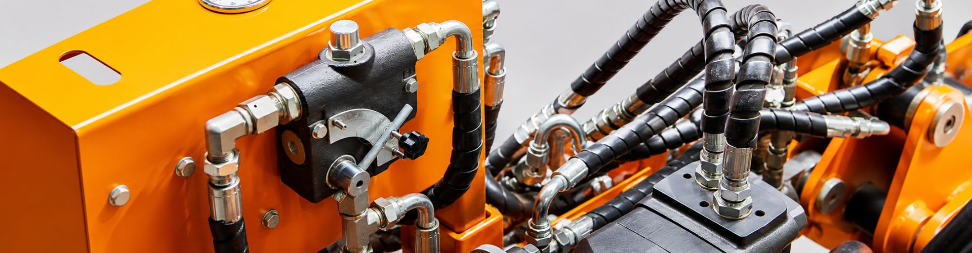
A one-piece fitting elbow drop length changes hose routing by moving the point where the hose centerline leaves the connection. A replacement can have the correct thread, sealing method, hose dash, and nominal elbow angle yet still place the hose too close to a guard, cylinder, frame, or neighboring port. The changed tangent point can also alter bend initiation, required hose cut length, and finished end-to-end dimensions. In a compact installation, those differences may make an apparently correct fitting impossible to install without harmful force or twist.
Angle Alone Does Not Define the Installation Envelope
Imagine a 90-degree hose end connected beside a machine guard. The old elbow turns the hose after clearing the guard, but the replacement begins the turn closer to the connection plane. Both are 90-degree fittings, yet the replacement moves the hose centerline into the guard.
The opposite change can also create a problem. A longer drop may clear the guard but move the hose toward a cylinder rod path or adjacent port. It can consume assembly length, reduce space for a natural bend, or place the hose against a surface during equipment movement.
Treat the fitting and hose as one envelope
Installation envelope means the three-dimensional space occupied by the connected fitting, hose tangent, bend, and nearby moving or fixed components. Thread and seal compatibility answer whether the connection can mate. Drop length helps answer whether the routed assembly can physically fit and move safely.
Never force the hose into alignment to overcome a geometric mismatch. Bending below the hose manufacturer’s minimum radius, twisting the hose, or using the connection to pull the assembly into place can damage the hose and load the fitting.
Define Drop Length From Controlled Reference Geometry
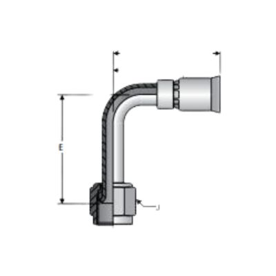
Drop length should be described with named reference planes and centerlines, because “height” or “overall length” can refer to different features. The exact dimensioning convention is drawing-specific.
Connection plane to hose centerline
A practical definition starts at a controlled connection reference, such as a seat plane, flange face, port-related datum, or another drawing-defined plane. The dimension then locates the outgoing hose or stem centerline relative to that reference. For an elbow, this establishes how far the hose path is offset when it leaves the connection.
The reference is not always the physical end of the thread. Threads, swivel nuts, seats, sealing faces, and body geometry can extend beyond or behind the functional connection plane. Measuring from whichever edge is easiest can produce a number that cannot be compared with the original drawing.
Drop differs from overall length
Overall fitting length may include a swivel nut, thread, nose, body, ferrule, and stem. It does not necessarily locate the hose centerline. Two fittings can have similar overall lengths but different elbow centers, or different overall lengths while producing similar routing offsets.
Record both values only when each serves a defined purpose. Drop controls the centerline location; other dimensions control connection engagement, body clearance, wrench access, hose insertion, and assembly cutoff relationships.
Drop Length Moves the Hose Tangent Point
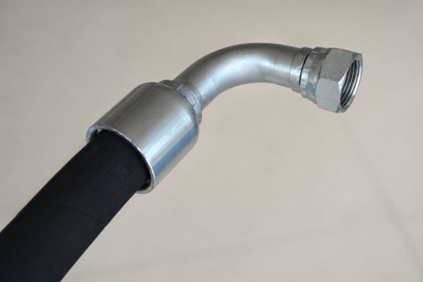
The tangent point is where the hose leaves the rigid fitting geometry and begins its free routed curve. Moving that point changes the available distance and direction for the hose to reach the next support or connection.
Shorter drop geometry
A shorter drop brings the outgoing centerline closer to the connection reference. In a compact port bank, this may reduce fitting projection, but it can also start the hose path too close to a block, nut, guard, or neighboring hose. The hose may need to bend abruptly just beyond the ferrule to reach its route.
That condition should not be “solved” by forcing a tighter curve. The minimum bend radius and any required straight length near the fitting come from the hose manufacturer’s current instructions. A shorter metal envelope is not useful if it removes the space needed for an acceptable hose transition.
Longer drop geometry
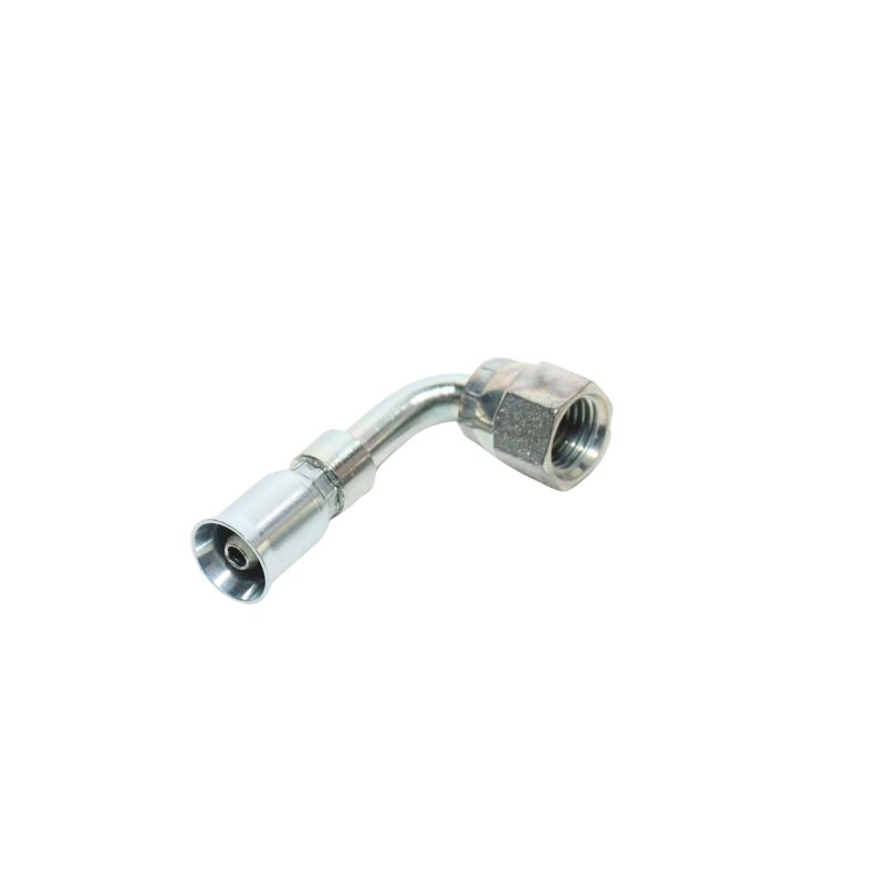
A longer drop moves the tangent point farther from the connection plane. It may clear one obstacle or allow a gentler approach, but it also projects the assembly into additional space. On moving equipment, that projection may enter a linkage path or increase leverage from hose weight and motion.
Longer is therefore not automatically better. The correct drop places the hose centerline within a workable routing corridor while preserving connection access, motion clearance, bend requirements, and support locations.
Compare Routing Consequences, Not Fitting Size Alone
Shorter and longer drop conditions create tradeoffs that depend on the machine envelope. A drawing overlay or physical routing template is often more informative than a catalog side view.
| Geometry condition | Hose centerline effect | Installation consequence |
| Shorter drop | Moves tangent point toward the connection plane | May reduce projection but crowd the hose against the port block or force an early bend |
| Matched functional drop | Reproduces the intended tangent point and route | Still requires verification of angle, rotation, cut length, and all connection details |
| Longer drop | Moves tangent point farther from the connection plane | May improve one clearance while creating interference, leverage, or excess assembly length elsewhere |
Test both fixed and moving clearances
Consider a hose routed between a valve bank and a close parallel panel. A shorter drop may trap the hose between the swivel and panel before it can turn. A longer drop may move the bend past the panel edge, but only if the projected body does not collide with another port or prevent wrench access.
In a second general scenario, a hose runs near a cylinder that sweeps through an arc. A fitting can clear the cylinder when equipment is stationary yet enter its motion envelope at full travel. Evaluate every relevant equipment position under safe, depressurized conditions and controlled load support.
45-Degree and 90-Degree Elbows Solve Different Routes
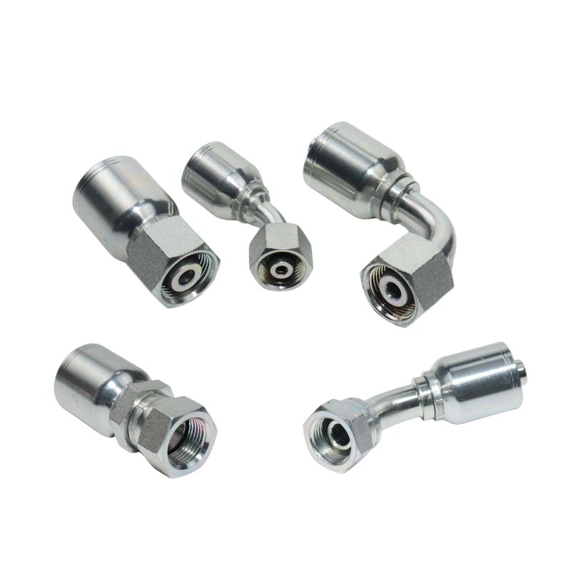
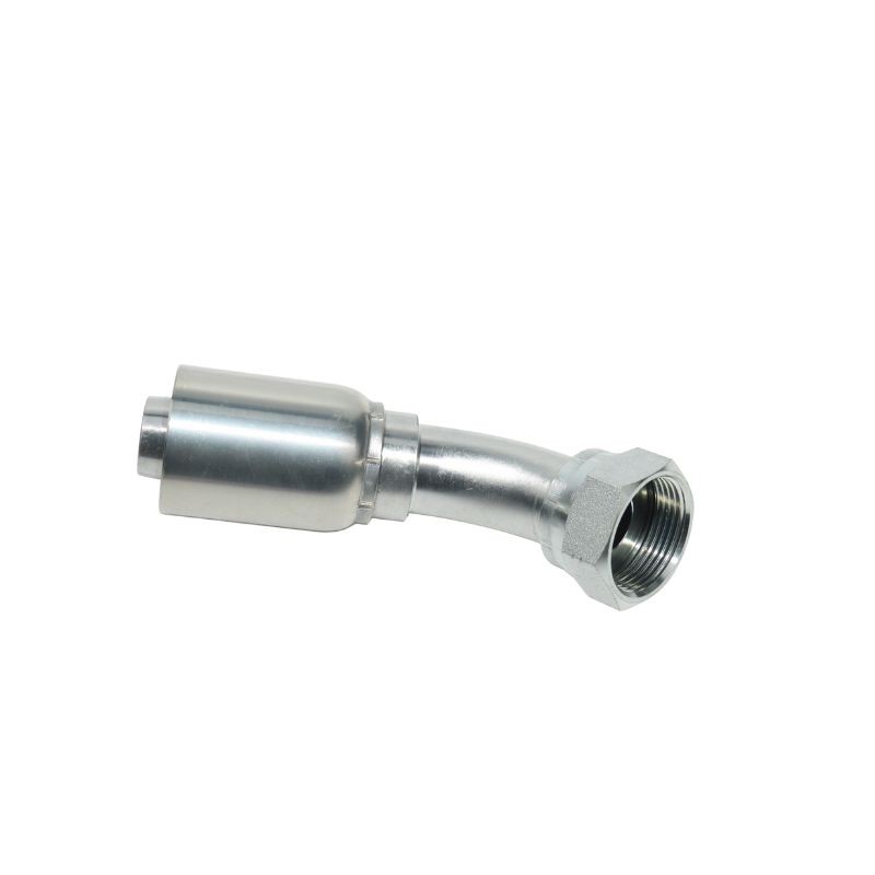
A 45-degree fitting changes direction more gradually at the metal end, while a 90-degree fitting turns the centerline farther before the flexible hose begins. Neither is universally better; the surrounding route determines which geometry fits.
A 45-degree elbow may work when the hose needs a diagonal departure and has enough space to complete the remaining curve. It can be unsuitable where a nearby wall requires an immediate right-angle turn. A 90-degree elbow can redirect the hose sharply in a compact port area, yet its body and drop may occupy more space in another direction.
Select by route rather than angle ranking
Comparing only angle ignores rotation around the connection axis. A 90-degree elbow pointed away from the routing corridor is no more useful than one with the wrong drop. Swivel capability may allow orientation during installation, but the final connected position and any anti-rotation requirements still need verification.
Do not replace a 45-degree with a 90-degree fitting merely to “make the hose reach.” Such a change affects centerline path, cutoff calculation, assembly length, clearance, and potentially hose loading. Treat it as a redesigned assembly requiring appropriate approval.
Drop Length Changes Hose Cut Length and Finished Dimensions
An elbow contributes a rigid centerline path before the flexible hose begins. Changing that rigid path changes how much hose is required to achieve the same installed endpoint and route.
Cutoff relationships are fitting-specific
Assembly calculations often use fitting cutoff or insertion-related dimensions to convert an overall assembly requirement into hose cut length. The exact convention depends on the fitting and hose system. A replacement with a different elbow center or stem relationship can change that contribution even when nominal size is unchanged.
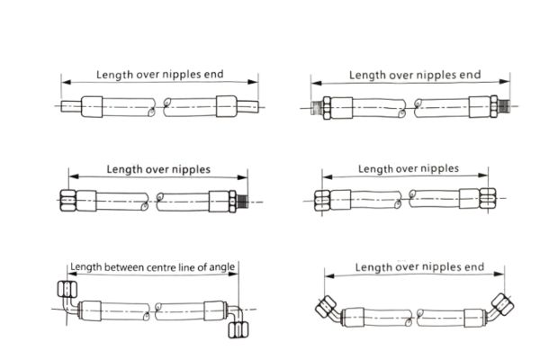
Do not subtract a generic elbow allowance or reuse a cutoff factor from a different fitting family. Use controlled fitting dimensions and the approved assembly calculation method. Verify whether the specified finished length is measured end-to-end, centerline-to-end, seat-to-seat, or from other functional references.
End orientation also matters
For assemblies with two angled ends, drop length interacts with relative clocking. A changed tangent point can shift the route even when the ends share the intended angular orientation. The assembly drawing should define both the linear references and the angular relationship.
After assembly, inspect finished length by the specified method without stretching or compressing the hose to force a reading. A correct nominal length with wrong drop can still miss the installed port geometry.
Check Clearance Throughout the Equipment Motion
Routing verification must include fixed structures and moving envelopes. Guards, frames, cylinders, linkages, adjacent ports, clamps, and service access can all be affected by elbow drop.
Inspect clearance at the connected fitting body, swivel or nut, ferrule, hose tangent, and first bend. Confirm that a tool can reach the connection without using the hose as a handle. Check whether nearby hoses can move without rubbing or crossing in a way that transfers load.
Review access, motion, and hose support
For moving equipment, secure raised or suspended loads, isolate the hydraulic system, release pressure and stored energy, and follow lockout and manufacturer instructions before measuring. Where a motion study is required, use an approved safe method rather than placing a person in a pinch zone.
Account for hose growth, pressure response, vibration, and equipment articulation using manufacturer and design data. A static gap is not automatically sufficient clearance. Protective sleeves and clamps can manage defined hazards but cannot correct a fundamentally wrong centerline path.
Measure an Elbow Replacement Before Ordering or Crimping
A replacement review should reproduce the original functional envelope, not just its connection label. Collect dimensions from controlled references and preserve orientation evidence before discarding the old assembly.
Connection and fitting geometry
Confirm connection standard, thread diameter and pitch or TPI, straight or tapered form, male or female configuration, seat angle, sealing face, and O-ring location where relevant. Record the elbow angle, drop from a defined connection plane to hose centerline, relevant overall dimensions, swivel behavior, and body clearance.
Photograph the complete fitting, connection, sealing surface, and installed orientation. Include a scale and label the datum used for every dimension. A photo supports screening but cannot identify the final fitting by itself.
Hose and installed route
Record hose manufacturer, series, construction, ID, dash size, reinforcement, fitting series, current crimp data, finished assembly length references, relative end orientation, and routing supports. Map the hose tangent point, first bend, obstacles, motion envelope, and required service access.
Compare the proposed fitting on an installation drawing or controlled template before crimping when possible. If drop, cutoff, or envelope evidence is missing, do not assume a matching thread and angle make the replacement dimensionally equivalent.
Conclusion
Elbow drop length controls where the rigid fitting hands the route to the flexible hose. A shorter drop may reduce projection yet force an early bend or crowd the port; a longer drop may clear one obstacle while entering another component’s envelope. The effect differs between 45-degree and 90-degree fittings and changes cutoff calculations, finished length, and two-end orientation. Correct threads, dash size, and angle do not prove dimensional equivalence. Before replacing a one-piece fitting elbow drop length, prepare the exact connection and sealing details, controlled drop datum, elbow centerline and overall dimensions, hose and crimp data, finished-length references, clocking, installed photographs, bend requirements, and clearance through every relevant equipment position.
FAQ
Is a 45-degree elbow better for hose routing than a 90-degree elbow?
No, each creates a different centerline departure. Choose from the installation envelope, required direction, bend space, orientation, and approved assembly design.
Is elbow drop length the same as overall fitting length?
No, drop locates the hose centerline from a defined connection reference. Overall length may include threads, nuts, body, stem, and ferrule features.
Does drop length affect the hose cutoff factor?
Yes, changed elbow geometry can alter the fitting’s contribution to finished assembly length. Use the controlled fitting-specific calculation, not a generic allowance.
Should a shorter drop always be used in a tight space?
No, a shorter drop can move the hose too close to the port or force an unacceptable early bend. Verify the complete three-dimensional route and service access.
What measurements are essential for an elbow replacement?
Record connection and seal details, elbow angle, drop from a defined plane, body envelope, hose centerline, cutoff references, clocking, hose identity, and installed clearance.