Private label starts with a controlled product definition, not a logo. A usable specification for private label one-piece hydraulic fittings connects technical identity, brand identity, packaging identity, approved evidence, and revision control so the same SKU means the same product at drawing, sample, order, receiving, and repeat-purchase stages. If these layers are managed separately, a correct fitting can receive the wrong label, a familiar carton can contain a changed revision, or new artwork can hide an unresolved technical difference.
Build One Product Definition Before Branding
A private-label line should begin with the product that must be identified and verified. Define the hose side, connection side, material and finish, controlled dimensions, sealing components, and applicable documents before approving artwork. Branding can distinguish the item commercially, but it cannot establish thread, sealing, hose, crimp, pressure, fluid, or application suitability.
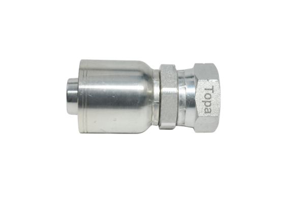
A one-piece hose fitting normally has its stem and ferrule preassembled, attached, or retained together, with construction varying by series. That arrangement may simplify separate ferrule picking, yet it does not make the fitting universal. The product definition must still identify the exact hose series, dash size, stem/ferrule family, port connection, and current assembly requirements.
Define the approval object
State whether approval applies to one part number, a controlled family, a packaging configuration, or a combination of these. A sample with an accepted logo does not automatically approve every size or connection sharing the artwork. The specification should map each approval to the exact SKUs and revisions it covers.
The approval object also needs a document hierarchy. An approved drawing should control technical geometry; the item master should control the internal SKU and description; artwork files should control marks and labels; packaging instructions should control unit, inner, and carton presentation. When fields overlap, designate which document is authoritative.
Organize Technical, Commercial, and Packaging Identity
Three connected identity layers keep departments from describing the same item differently. Technical identity answers what the fitting is. Commercial identity answers how the brand orders and sells it. Packaging identity answers how receiving and warehouse teams recognize the unit and quantity.
Technical identity
Record the exact fitting type and orientation; connection standard; thread diameter and pitch or TPI; straight or tapered form; male or female arrangement; seat, sealing face, and O-ring details; port dash; hose dash; compatible hose series; stem/ferrule family; material; finish; and controlled dimensions. Do not collapse these into a phrase such as “standard hydraulic fitting.”
Hose-side assembly data should point to current approved preparation, insertion, die, crimp, and inspection information. Do not place universal crimp values in a brand specification. Suitability depends on the exact hose manufacturer, series, construction, size, fitting series, ferrule, equipment, and validated data.
Commercial and packaging identity
Commercial identity includes the brand part number, sales description, product family, unit of measure, barcode assignment, and any approved market-facing description. Packaging identity includes unit bag or box, label content, inner quantity, carton quantity, carton mark, and document or barcode relationships. These fields should reference the technical SKU rather than create a parallel product definition.
| Specification field | Primary owner | Approval evidence | Change-control need |
| Thread, seat, seal, hose side, and dimensions | Engineering or technical authority | Approved drawing and technical record | Technical impact review and possible reapproval |
| Material, plating, and O-ring | Engineering and quality | Approved specification and linked evidence | Compatibility and conformity review |
| Brand part number and description | Product-data owner | Approved item-master record | Duplicate and cross-reference check |
| Product mark or logo | Brand owner and quality | Controlled artwork and marked sample | Legibility, location, and traceability review |
| Barcode and unit label | Product-data and operations owners | Scan test and approved label file | System mapping and receiving review |
| Unit, inner, and carton packaging | Operations and quality | Packaging instruction and approved sample | Product protection and quantity review |
| Golden sample or approved first sample | Cross-functional approval team | Signed approval record linked to revision | Baseline control; replacement requires disposition |
| Drawing, artwork, and packaging revisions | Document-control owner | Revision history and release record | Mandatory effective-date and segregation control |
Create Model Numbers and SKU Rules That Prevent Ambiguity
A private-label part number should resolve to one controlled sellable item. If the same code can describe different thread standards, port sizes, hose dashes, orientations, materials, finishes, or packaging units, quoting and warehouse accuracy will depend on tribal knowledge.
Use a conceptual structure rather than copying an assumed industry code. For example, an internal rule might concatenate controlled segments for product family, connection family, port size, hose size, orientation, material/finish option, and packaging variant. The segments are placeholders defined by the brand; they are not a universal standard and should never replace the technical description.

Separate intelligence from stability
An intelligent code can help people screen an item, but too much embedded meaning makes future changes difficult. Decide which characteristics belong in the permanent part number and which should remain attributes in the item master. A plating change may require a new SKU in one control system and a revision in another, depending on traceability, inventory segregation, customer commitments, and approved policy.
Before releasing a code, check for duplicate or near-duplicate descriptions. Resolve conflicting abbreviations, normalize dash and thread notation, and confirm that barcode records point to the same unit of measure. Preserve cross-references when an old code is retired so repeat orders do not silently map to a different product.
Freeze Technical Characteristics Before Artwork
Artwork should be built around a stable product record. Freeze the fields that determine identity and technical conformity before choosing mark location, label layout, or carton text. Otherwise, late technical changes can leave approved artwork attached to obsolete geometry or sealing information.
The freeze package should contain:
- Brand and technical part numbers with an unambiguous description.
- Connection-side standard, size, seat, seal, and orientation.
- Hose-side dash, approved hose series, and fitting family.
- Drawing with controlled dimensions and current revision.
- Material, finish, O-ring, and other sealing-component requirements.
- Product marking content, location, method, and legibility criteria.
- Required technical and traceability evidence.
Do not freeze a compatibility claim that has not been verified. Matching appearance, common dash size, or a cross-reference number does not prove interchangeability. Pressure suitability is limited by the lowest-rated component in the complete assembly, and fluid and temperature suitability may depend on hose, fitting, plating, and seal materials.
Link the artwork to exact technical revisions
The artwork record should name the part or family covered and the technical revision used when it was approved. A generic logo file can remain common, but the controlled print file should specify size, placement, orientation, and any part or batch marks. Keep approval evidence readable without exposing confidential production information in customer-facing artwork.
If physical space limits the mark, decide which identifier is essential for product and batch traceability. Do not shrink required information until it becomes unreadable or place marks on sealing faces, threads, or other functionally sensitive surfaces.
Connect Packaging, Barcodes, and Documentation
Packaging is part of item identity and product protection, not an isolated graphic project. A unit label should scan to the same SKU, description, and unit of measure shown on the purchase order and receiving record. Inner and carton labels should reconcile quantity and lot information without creating duplicate item codes.
Define the hierarchy from individual fitting to unit pack, inner pack, and shipping carton. State which layer carries the brand part number, technical cross-reference, barcode, quantity, revision where applicable, batch or lot identity, and handling information. Carton quantity should be controlled rather than inferred from box size.
Packaging approval should also consider protection of threads, sealing faces, O-rings, plating, and orientation-sensitive parts. Do not claim that one packaging method is universally sufficient; the instruction should reflect the actual product, transport, storage, and receiving needs.
Test the data flow, not just the printed appearance
Scan the barcode into the intended ERP or warehouse process and confirm that it returns the correct SKU and unit. Compare the unit label, carton mark, packing list, purchase order, and item master. A beautiful label that maps to the wrong quantity or old part number is a control failure.
Keep master artwork separate from print-generated variable data. Logo and fixed text may be controlled in the artwork file, while batch, quantity, or production date may come from a verified system. The specification should show which source owns each printed field.
Make Sample Approval the Production Baseline
Sample approval should verify the combined definition: technical product, mark, label, and packaging. A “golden sample” can support visual comparison, but it must stay linked to the approved drawing, evidence, artwork, packaging instruction, and revision. A physical sample alone cannot preserve hidden dimensions or document history.
Evaluate technical characteristics separately from appearance. Confirm identity, thread and sealing features, controlled dimensions, material and finish evidence, O-ring or sealing components, marking, and applicable assembly information. Then inspect label content, barcode mapping, packaging configuration, and traceability fields.

Approval should state the disposition clearly:
- Approved for the listed SKUs and revisions.
- Approved with a documented deviation and defined limits.
- Held pending clarification, evidence, or correction.
The first production order should be compared with this baseline under a defined inspection plan. Sample approval does not independently prove pressure, impulse, hose, crimp, or end-use suitability; separate validation remains necessary where applicable.
Control Revisions as One Connected Change
Any controlled-field change should begin with a change request that identifies affected SKUs, documents, inventory, orders, and approvals. Technical changes such as material, dimensions, plating, O-ring, stem, ferrule, or hose compatibility may require technical evidence or reapproval. Brand, label, barcode, and packaging changes may appear commercial yet still affect item identity and traceability.
Assign an effective date or lot, segregate old and new revisions, and prevent mixed stock from being shipped under one ambiguous label. Update the drawing, item master, artwork, packaging instruction, inspection record, and sample baseline together where affected. Do not let a supplier, printer, warehouse, or sales system implement one part of the change before the release is complete.
A minimum private-label specification package should contain:
- Controlled technical drawing and product specification.
- Item-master record, SKU rule, description, and cross-references.
- Product marking and label artwork with barcode mapping.
- Unit, inner, and carton packaging instructions.
- Approved sample or first-article evidence linked to revisions.
- Change history, effective lot, and old/new inventory disposition.
- Batch traceability and receiving-inspection requirements.
Optional advanced fields may include multilingual label variants, market-specific documentation, structured product-data exports, digital drawing links, and additional serialization. Add them only when they solve an operational requirement and remain under the same change-control system.
Conclusion
A dependable private label program controls one product definition across engineering, brand data, packaging, receiving, and repeat orders. Establish the exact fitting and hose-side identity first, create unambiguous SKU rules, and freeze technical characteristics before artwork. Link product marks, barcodes, carton quantities, and documents to the same item record. Approve samples as evidence packages rather than logo displays, then control every later change through revisions, effective lots, segregation, and updated baselines. Branding never replaces verification of thread, seal, hose, crimp, pressure, fluid, temperature, or application requirements. Make ownership and effective dates explicit across every connected record. For private label one-piece hydraulic fittings, prepare the controlled drawing, item master, artwork, packaging instruction, approval evidence, and traceability plan before releasing the first production order.
FAQ
Does an artwork change require a new technical approval?
Not automatically, but it requires change review to confirm what the artwork affects. Mark location, part identity, traceability, or functional surfaces may create technical or inspection implications.
When should a private-label SKU change?
Follow the approved item-governance rule based on identity, interchangeability, inventory segregation, and customer commitments. Do not keep one SKU when the code would conceal a materially different product or pack.
Does a plating change require reapproval?
It may because finish can affect corrosion behavior, dimensions, appearance, fluid exposure, and prior commitments. Review technical impact and required evidence before choosing the approval path.
Can packaging-only revisions use the same product revision?
They may when review confirms no product or traceability impact, but the packaging document still needs its own controlled revision and effective point. Barcode, quantity, protection, and label mapping must remain correct.
When is sample reapproval needed?
Reapproval is needed whenever the approved policy or impact review shows that a changed field could invalidate the baseline. The scope should match the change rather than repeating every test without reason.