How to Control Engineering Change for One-Piece Fittings

How to Control Engineering Change for One-Piece Fittings

A change that looks minor can invalidate downstream approval. Moving a mark, changing an O-ring source, adjusting plating, correcting a dimension, replacing tooling, or revising a carton label may affect function, identity, traceability, assembly, or customer commitments. Engineering change control for one-piece fittings should therefore manage a lifecycle: request, classification, impact assessment, evidence, approval, implementation, lot segregation, traceability, and closure. The rigor should match the risk rather than treating every change identically.

A Minor Change Can Alter the Approved Product

The first control is to describe what will actually change, not how easy it is to implement. A different plating bath may affect finish requirements; an O-ring substitution may affect fluid and temperature suitability; a label correction may change the barcode mapping; a tooling replacement may shift controlled dimensions even when the drawing stays unchanged.
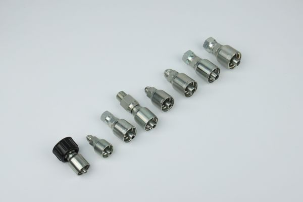
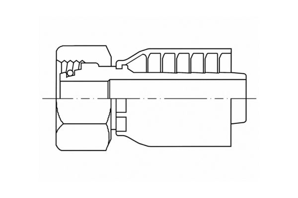
Parker 43series Hydraulic Fitting

Open an engineering change request before implementation. Record the affected part numbers, current and proposed states, reason, requester, documents, process steps, inventory, open orders, and expected effective point. Attach evidence rather than relying on an email that says “same as before.”

Protect the current baseline

Freeze the currently approved drawing, specification, sample, process, inspection plan, packaging instruction, and revision identifiers as the comparison baseline. Without that snapshot, reviewers cannot distinguish a proposed change from an undocumented condition that already exists.

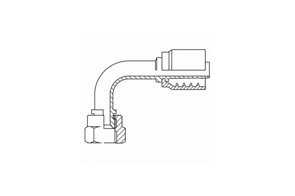
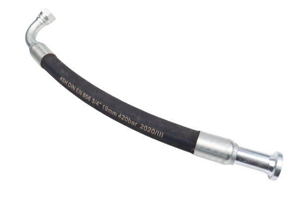
A one-piece fitting has a stem and ferrule preassembled, attached, or retained together, with construction varying by series. A change to either component, their retention, the hose tail, or assembly data may affect hose compatibility and crimp requirements. The port connection, material, finish, and seals create separate impact paths.

Classify Technical, Process, Identification, and Document Changes

Classification routes the change to the right questions; it does not decide approval by itself. One request may belong to more than one class. A material change, for example, can also change machining, plating, marking, inspection, and documentation.

Separate a correction from a requirement change

A document correction may be low risk when it fixes spelling or formatting without changing the technical meaning. If a “correction” alters a dimension, tolerance, material, seal, method, or acceptance criterion, it is a requirement change and needs the corresponding impact review.

Do not classify by department. A packaging request from marketing may affect traceability; a tooling request from production may affect dimensions; a supplier-requested material change may affect application suitability. Classify by possible effect.

Perform Impact Review Before Approval

Impact review should trace the proposed difference through product, process, assembly, application, commercial records, and inventory. Reviewers need the exact before-and-after state plus evidence sufficient to evaluate each affected path.

For technical product changes, consider connection standard, thread, seat, sealing face, O-ring, material, finish, controlled dimensions, pressure basis, fluid, temperature, corrosion exposure, and equipment requirements. For the hose side, consider hose manufacturer and series, construction, dash size, stem/ferrule family, preparation, insertion, crimp equipment, die, and current approved crimp data.
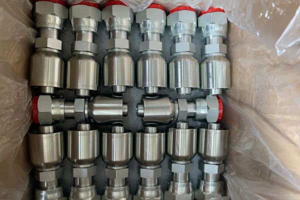
Flange Fitting protection

Review downstream operations

Ask how the change affects quoting, purchasing, receiving, warehouse picking, assembly, inspection, service, and repeat orders. A revised part that remains under the same SKU may be mixed with old stock unless labels and effective lots separate it. A new SKU can still create confusion if cross-references and open orders are not updated.

Review installed or field inventory when the change corrects a potential technical problem. The response may require containment or additional assessment, but do not infer a universal field action without evidence. Scope and urgency should follow the identified risk and responsible authority.

Document the impact conclusion for every relevant category: affected, not affected with rationale, or unknown pending evidence. “No impact” without a reason is not an assessment.

Refresh Evidence According to the Impact

Evidence should answer the risks raised by the change. A revised critical dimension may need an updated drawing, dimensional results, sample, and affected functional validation. A label-only correction may need artwork review and scan verification without repeating unrelated technical tests.

Possible evidence includes revised drawings, material or plating records, seal data, dimensional reports, thread inspection, samples, first-article review, process qualification, assembly checks, or tests required by the approved quality plan. This is not a universal list, and no fixed test scope applies to every change.

When reapproval is likely

Reapproval is likely when the change can affect product identity, fit, sealing, hose engagement, material compatibility, controlled dimensions, pressure or impulse basis, surface finish requirement, O-ring performance, or an approved customer characteristic. It may also be required when tooling or process changes can shift these outputs even if the drawing is unchanged.

When document-only control may be enough

Document-only control may be enough when review demonstrates that a change corrects formatting, spelling, or an administrative field without altering identity, function, traceability, inspection, packaging quantity, or customer commitments. Preserve the impact rationale and approval; do not use the category to bypass evidence for a technical change.

Route Approval and Visibility Before Implementation

Approval routing should follow impact ownership. Engineering reviews technical definition and compatibility; quality reviews evidence and inspection; operations reviews process and packaging; product-data owners review SKU, label, and barcode; purchasing and planning review orders and stock; customer-facing functions review commitments where applicable.

The change record should identify required approvers rather than collecting broad “FYI” acknowledgments. Each approval confirms a defined responsibility. Missing authority should place the request on hold, even when the physical change is easy to make.

Notify people who control affected transactions

Visibility must reach the teams that can accidentally use the old state. Update production travelers, inspection plans, supplier orders, item masters, warehouse instructions, and customer documents before the effective point. Do not depend on one meeting or mailbox thread as the only control.

Supplier-requested changes require the same internal impact review as internally requested changes. A statement that the replacement is equivalent is a proposal, not proof. Obtain the before-and-after definition and applicable evidence before approval.

Set Effective Lots and Segregate Old and New Revisions

Approval does not complete implementation until the effective point is traceable. Define the first affected lot, serial range where used, production date, order, or another controlled boundary appropriate to the system. Avoid vague phrases such as “next shipment” when multiple orders or stock locations exist.

Old and new revisions should remain distinguishable in production, inspection, storage, and shipment. Use lot identity, physical segregation, labels, status controls, and system records. If the same SKU continues, ensure users can still determine which revision a specific part belongs to.

Decide the old-stock disposition

Old stock may remain approved, require reinspection, need rework, be restricted to a defined use, or be rejected. The decision depends on change impact and authorized disposition; it cannot be inferred from the fact that a new revision exists.

Check work in process, supplier stock, receiving holds, warehouse stock, kits, open orders, returns, and retained samples. Mixed old/new cartons defeat traceability even when both revisions are individually acceptable. Packaging and paperwork must preserve the segregation.

Handle Urgent Corrections Without Bypassing Control

An urgent correction may shorten the decision timeline, but it should not erase classification, impact assessment, authority, or traceability. Create an emergency change path that identifies the immediate risk, containment, temporary approval, affected scope, and deadline for permanent documentation.

For an emergency tooling change, verify what characteristics the tool can influence and inspect or qualify accordingly before releasing output. For a marking correction, prevent misidentified stock and verify barcode or part mapping. For a technical nonconformity, contain affected lots while responsible engineering defines disposition.
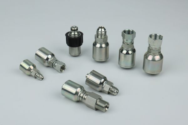
43 series Crimp Fitting

Temporary authorization must have boundaries: parts, lots, orders, operations, and expiry or closure condition. Convert an accepted permanent correction into the standard change process with revised documents and baseline evidence. Do not allow an emergency note to become an indefinite alternate process.

Planned changes should use enough lead time to update documents, evidence, orders, and stock controls before implementation. No universal notification period fits every product or customer; timing should follow contractual requirements, risk, and the operational work needed to prevent overlap.

Close the Workflow Only After Verification

Closure should confirm that the approved change was implemented as intended and that affected systems agree. Verify the first effective lot, inspection results, document availability, labels, packaging, inventory segregation, and transaction records. Resolve open deviations and confirm that obsolete instructions are withdrawn from points of use.

Use this workflow from request to closure:

Closure evidence should be searchable from the part and revision. If a later complaint or repeat order cannot identify which change applied, the workflow did not achieve traceability even if all signatures are present.

After closure, monitor the first relevant production and receiving records for unintended effects identified in the risk review. This is not permission to release an uncertain change and learn from failures; approval evidence must exist first. Monitoring checks whether implementation matched the approved plan, whether old documents or stock reappeared, and whether downstream systems retained the correct revision. Record any new issue as a separate nonconformity or change request rather than editing the closed record without history.

Conclusion

Engineering change control keeps a fitting’s approved definition aligned with production, documents, stock, and repeat orders. Describe the exact change, classify all affected paths, assess impact before approval, and collect evidence proportional to technical and operational risk. Route decisions to responsible owners, then implement through a defined effective lot, old/new segregation, updated records, and first-lot verification. Urgency can accelerate review but cannot remove containment, authority, or traceability. Not every change needs identical reapproval, yet every change needs a reasoned disposition. Keep the approved baseline accessible after formal closure. For engineering change control for one-piece fittings, prepare the before-and-after definition, affected SKUs, application and assembly impacts, evidence plan, approval route, stock disposition, and closure criteria before anything reaches production.

FAQ

How should a supplier-requested fitting change be handled?

Treat it as a formal proposal and obtain the exact before-and-after definition plus evidence. Internal owners must assess and approve the impact before implementation, regardless of an equivalence claim.

Can an emergency tooling change be implemented immediately?

Only through an authorized emergency path with containment, affected-characteristic review, required verification, traceable scope, and closure conditions. Urgency does not prove the new tool preserves controlled outputs.

Does every plating change require full reapproval?

Not necessarily, but every plating change needs impact review. The evidence and reapproval scope depend on finish requirements, dimensions, corrosion exposure, appearance, fluid, temperature, and approved commitments.

Can a label-only change use document-only control?

It may when review confirms no effect on product identity, barcode mapping, traceability, unit, or commitments. The artwork, system fields, and effective point still require controlled approval.

What should happen to mixed old and new stock?

Place it under controlled status, identify each revision or lot, and apply the authorized disposition. Do not relabel an ambiguous mixture or ship it as one revision without evidence.

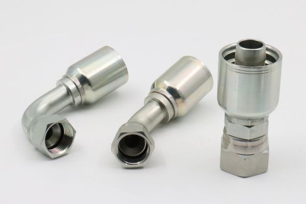
What Should OEM FAI Check for One-Piece Fittings

What Should OEM FAI Check for One-Piece Fittings?

An OEM first article decision must prove that the exact inspected fitting conforms to the approved product definition before repeat production is released. An appearance check alone cannot do that. An OEM FAI check for one-piece fittings should link sample identity, drawing revision, measured characteristics, thread and sealing verification, material and finish evidence, O-rings, markings, deviations, and applicable test records in one review package. The result is an approval gate: release when required evidence is complete and acceptable, approve a controlled deviation only through authorized disposition, or hold when the sample, reference, method, or result is unclear. Separate application validation remains necessary where the FAI scope does not cover it.

Define What the FAI Must Prove Before Release

First article inspection should answer whether the first production-representative article matches the controlled technical and identification requirements used for the order. It is not a general statement that every future part will conform, nor is it a substitute for process control, incoming inspection, or batch traceability.

The gate should verify three links: the physical sample links to a part and lot; the inspection results link to approved characteristics and methods; and the disposition links to authorized reviewers. If any link is missing, an attractive sample can still be technically unverified.

crimp Fitting stocks

Set the scope from risk and requirements

List the characteristics and evidence required by the approved drawing, specification, order, and quality plan. Distinguish dimensions, threads, sealing features, material, plating, O-ring, marking, packaging, and linked tests. Do not invent universal tolerances, sample quantities, or test requirements; the responsible documents must define them.

A one-piece fitting has a stem and ferrule preassembled, attached, or retained together, with construction varying by series. FAI should confirm that controlled relationship where required, but it does not independently prove compatibility with every hose. Hose manufacturer, series, construction, dash size, preparation, crimp equipment, die, and current crimp data may require separate approval.

Identify the Exact First Article and Document Set

The package must make substitution or document drift visible. Record the internal and external part numbers, product description, sample or piece identifier, manufacturing lot or batch, order reference, sample date, and applicable revision status. Mark photographs or sample tags so reviewers can connect results to the inspected article.

The document index should identify the approved drawing and revision, technical specification, material and finish requirements, seal specification, inspection plan, applicable assembly or test documents, and any approved change or deviation. Avoid attaching files without revision identifiers because reviewers cannot tell whether they represent the released baseline.

Reconcile conflicting references before measurement

If the purchase order, drawing, catalog description, or sample mark disagrees, place the FAI on hold and resolve authority before evaluating results. Inspecting against a convenient document only creates a polished report for the wrong requirement.

Record units and datum conventions. Dimensions described as overall length, centerline length, seat reference, or gauge position must use the drawing’s definition. A measurement without its reference point cannot be compared reliably, especially for elbows, swivel nuts, and sealing features.

The minimum identity pack should contain:

Review Dimensions and Threads as One Evidence Block

Dimensional and thread results should demonstrate conformance characteristic by characteristic. The report must show the controlled reference, inspection method, result, and disposition without replacing actual values with “looks acceptable.”

metric 24° oring crimp fitting

Dimensional verification

Create a ballooned or otherwise indexed drawing where the quality system requires one, then map each characteristic to the results record. Distinguish nominal values, tolerances, measured results, and pass/fail status. Use calibrated equipment suitable for the characteristic and record the method or equipment identity according to the approved procedure.

Critical dimensions may include connection geometry, hose-tail and ferrule features, wrench flats, centerline dimensions, overall references, or sealing-face relationships. The exact list comes from the drawing and risk review. Do not copy dimensions from another dash size or visually similar part.

Thread and sealing-interface verification

Thread inspection should confirm the defined standard, diameter, pitch or TPI, straight or tapered form, male or female arrangement, and applicable gauge result. A thread gauge result should be linked to the correct gauge type and current status; a mating part or hand fit is not an equivalent controlled method.

Review Material, Plating, and Seals as a Second Block

Material evidence should link the article or production lot to the approved base-material requirement. A generic certificate title or supplier declaration without part, heat, batch, or other required traceability may not establish the connection. Review the document scope, identifiers, revision, and applicable results under the quality plan.

Plating or finish evidence should identify the controlled specification and sample or lot relationship. Appearance can reveal obvious damage or inconsistency, but color alone does not prove material, coating system, thickness, corrosion performance, or conformity. Do not convert an unsupported salt-spray statement into a prediction of field service life.

Treat O-rings and sealing components as controlled parts

Where the design uses an O-ring, bonded seal, or other sealing component, verify identity, material requirement, size or controlled geometry, location, condition, and evidence as specified. A black elastomer ring cannot be approved by color. Fluid and temperature compatibility need the applicable material and application data.

Check whether the seal arrived installed, packaged separately, lubricated, protected, or marked as required. Missing, cut, twisted, contaminated, or incorrectly seated seals should be recorded as actual findings, not corrected silently before the report photograph.

Separate Visual and Packaging Checks from Functional Checks

Visual checks cover workmanship features that can be observed under the defined method: damage, burrs where controlled, contamination, marking, plating appearance, component presence, and packaging condition. Marking checks confirm part number, logo where applicable, lot identity, legibility, and location against approved artwork.

Packaging checks confirm unit protection, caps where specified, labels, barcode mapping, pack quantity, and carton identification. These controls matter to receiving and traceability, but passing them cannot compensate for a failed thread, dimension, material, or seal requirement.

Functional technical checks must remain linked to their approved procedures. If pressure, impulse, retention, leakage, or assembly tests are required, record the test document, specimen relationship, method, and disposition. Do not claim that routine dimensional FAI proves pressure, hose, crimp, or end-use suitability when those characteristics were not validated in scope.

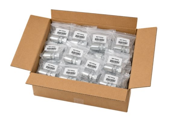
clear label

Preserve independence of evidence

Avoid one broad “appearance passed” checkbox that covers marks, faces, threads, and packaging. Separate results make later changes and failures traceable. They also allow a packaging correction without pretending a technical characteristic was reinspected.

Photographs support identity and visible-condition review. They cannot replace measurements, gauges, material evidence, or test records. Store them with labels showing which sample, surface, and revision they represent.

Record Deviations and Make an Explicit Disposition

Every nonconforming or unclear result needs a record that identifies the characteristic, requirement, actual result, impact review, and authorized disposition. Editing the drawing, rounding the measurement, replacing a seal, or reworking a mark without recording the event destroys the evidence chain.

Pass, approved deviation, or hold

Pass means the required evidence shows the characteristic meets the released requirement. Approved deviation means an authorized review accepts a specific departure for a defined scope, such as identified samples or lot, without rewriting the general requirement. Hold for clarification means the requirement, method, traceability, result, or authority is insufficient to make a release decision.

An approved deviation is not a permanent drawing change. Link it to the affected part, lot, quantity, order, and approval, then state whether future production must return to the original requirement or follow a formal engineering change. Do not use FAI approval to normalize an unexplained difference.

Contain related samples and production until disposition is clear. If rework is allowed, preserve before-and-after evidence and reinspect affected characteristics plus any features the rework could influence.

Establish the Baseline and Make the Release Decision

The approved FAI package becomes a reference for future production inspections, but its fields must be translated into operational controls. Identify which characteristics are checked by lot, which documents must accompany shipments, what markings and packaging remain controlled, and which revision is effective.

Keep the approved drawing, indexed report, evidence documents, photos, deviation records, and approval signatures together. A retained sample may support visual comparison, but storage condition and identification must prevent damage or mix-up. Never let the sample replace the current drawing or specification.

Before release, confirm:

Release repeat production only when all required evidence is accepted and no unresolved hold remains. FAI approval should trigger document retention and production-control activation, not remove the need for future batch inspection or change notification.

Communicate the release status to purchasing, production, receiving, and document control using the same revision identifiers. Open orders and stored labels should be checked before the effective release so an obsolete drawing or unapproved package does not reenter the process. When the FAI is held, the system should block repeat production rather than relying on an email reminder.

Conclusion

First article inspection is a release gate built from traceable evidence, not a visual endorsement. Identify the exact sample and revision, map dimensions and threads to controlled references, and review material, plating, O-rings, sealing features, markings, packaging, deviations, and linked tests as distinct evidence blocks. Record actual results and methods, then choose pass, authorized deviation, or hold without hiding uncertainty. The approved package should establish the drawing, inspection, traceability, and change-control baseline for future production. An OEM first article inspection for one-piece fittings does not alone prove hose, crimp, pressure, fluid, temperature, or end-use suitability. Before release, prepare the complete document index, results record, deviation dispositions, and separate validation evidence required by the application, and assign clear owners for open actions.

FAQ

How many samples should a one-piece fitting FAI include?

Use the quantity defined by the approved quality plan, risk assessment, order, or responsible engineering requirement. Do not apply an invented universal sample count to every fitting or characteristic.

What happens when the drawing revision changes after FAI?

Review the change’s impact and define which evidence, samples, measurements, or tests must be refreshed. The old approval does not automatically cover characteristics changed by the new revision.

Can an approved deviation become the new normal requirement?

No, not without formal change control. A deviation applies only to its authorized scope; a permanent requirement change needs revised documents, impact review, and appropriate reapproval.

Should destructive tests be part of every FAI?

Not automatically, because test scope depends on the approved requirements and risk. When destructive testing is required, link the specimen, method, result, and disposition to the FAI package.

What controls are needed after FAI approval?

Activate the defined production inspections, document revisions, traceability, packaging controls, and change-notification process. Future batches still require conformity evidence under the approved control plan.

How One-Piece Fitting Clocking Errors Affect Hose Assemblies

How One-Piece Fitting Clocking Errors Affect Hose Assemblies

One-piece fitting clocking errors occur when two angled end fittings have the wrong relative rotational orientation around the hose centerline. Fitting angle describes the individual elbow shape, while clocking describes how one end is rotated compared with the other. Both fittings can have the correct thread, seal, dash size, bend angle, and drop length yet still fail to align with fixed machine ports. Trying to install a misclocked assembly can twist the hose, load the connections, violate the intended route, or make installation impossible.

Fitting Angle and Assembly Clocking Are Different

A 90-degree fitting turns its own centerline through a right-angle geometry; that is the fitting’s bend angle. Clocking compares the direction of one angled end with the direction of the other after both are attached to the same hose.

Imagine looking along the hose axis from one end. The first elbow points upward. The second elbow might point upward, sideways, downward, or somewhere between. That relative rotation is the clocking relationship. Changing it does not turn either 90-degree elbow into a different bend angle.

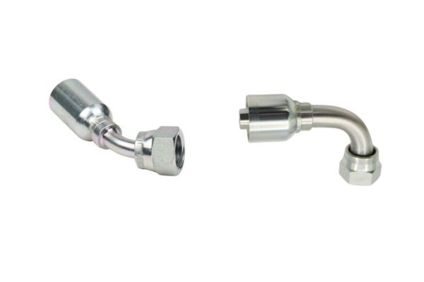
45 90 degree crimp Fitting

Separate angular orientation from fitting geometry

Drop length is another separate variable. It locates the hose centerline relative to the connection plane. An assembly can have correct clocking but wrong drop, or correct drop but wrong clocking. Troubleshooting should keep angular orientation, elbow angle, and linear offset in separate records.

Straight fittings usually do not establish a strong rotational direction unless they contain an orientation-dependent feature. This is why a straight-to-elbow assembly is generally less sensitive to relative clocking than an elbow-to-elbow assembly.

Define a Repeatable Angular Datum

Clocking cannot be inspected reliably from “looks about right.” The assembly drawing or work instruction needs a reference end, a viewing direction, a zero direction, and a defined feature representing each angled end.

A practical method designates one fitting as the reference and places its centerline or another controlled feature at zero. The second fitting is described by its rotation when viewed from a stated end. A clock-face description can communicate orientation visually, while a degree-based description can support measurement.

State reference end, view, and zero

For example, the reference elbow could be placed conceptually at twelve o’clock and the second described relative to it. This is only an illustration. Organizations can use different viewing directions, positive-rotation conventions, and datum features, so the actual drawing must state its convention.

Swivel nuts should not be mistaken for elbow-body orientation. A nut can rotate for connection while the stem or elbow direction remains the feature that establishes the hose route. Mark and measure the controlled body centerline, not a movable wrench flat unless the instruction defines it.

How Clocking Error Enters During Assembly

Clocking error is introduced when the second angled fitting is positioned or moves relative to the first before its orientation becomes fixed by crimping. Process controls should preserve a defined angular relationship through insertion, setup, and die closure.

The wrong drawing view or viewing direction can reverse the intended rotation. An operator can also reference an inconsistent feature, place the hose on a bench without controlling natural curvature, or align to a movable nut rather than the elbow centerline. Faint, misplaced, or ambiguous orientation marks can add variation.

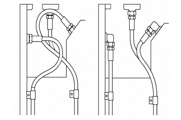
Assembly routing

Control movement before the second crimp

Movement can occur while the assembly is transferred to the crimper or positioned in the dies. Hose stiffness and memory may rotate an unsupported end. If one end is crimped first, the hose can relax or roll before the second is fixed. Tooling clearance can also make visual alignment difficult.

The solution is not to hold the fitting by force during an improvised closure. Use the approved fixtures, references, marks, sequence, and inspection method for that assembly. Machine operation and crimping must follow current manufacturer data.

A Small Angular Error Becomes Hose Twist in Installation

Fixed ports demand that both ends arrive at specific positions and orientations. If the second end is rotated from that relationship, installers may try to twist the hose body until the connection faces the port.

Twist distributes torsion along the hose and changes reinforcement geometry. It can also shift the natural bend plane, pull the hose against guards, or add side load to fitting connections. The assembly may look connected while carrying stored installation strain.

Installation converts angle into torsion

The visible rotation at the fitting can appear small, yet its practical effect depends on hose length, stiffness, routing, end geometry, and port constraint. No universal angular error can be declared harmless. A short, stiff assembly between fixed ports may react strongly, while a longer route may visually absorb rotation but still retain undesirable torsion.

Do not use hose flexibility as permission to compensate. Hose should be routed without twist according to manufacturer instructions. If ends do not align in a relaxed state, stop, verify the assembly drawing and measurements, and evaluate remake or approved disposition.

Double-Elbow Assemblies Are More Clocking-Sensitive

Two angled ends each create a directional vector, so their relative rotation directly controls whether both connections can meet their ports. A straight end has no comparable elbow direction, making straight-to-elbow assemblies less constrained in this specific way.

Relative direction controls the two-end fit

Two 90-degree fittings can be intended to lie in the same plane, face opposite directions, or occupy different planes. Their individual bend labels do not reveal which arrangement is correct. The assembly drawing must carry that information.

A 45-degree and 90-degree combination is also clocking-sensitive. Their centerlines are different, but both define direction. Inspection should reference the intended outgoing centerline of each end rather than comparing body edges that may not be parallel.

Hose Length and Stiffness Change Severity

Clocking error is angular, but the resulting installation strain depends on the flexible section between the ends. Length, construction, diameter, reinforcement, temperature, and natural curvature influence how the hose reacts.

A short assembly has little flexible distance over which rotation can appear, so misalignment may prevent the nuts or flanges from reaching their ports. A long assembly may allow the end to be rotated into place more easily, but that action can distribute twist invisibly along a broad curve.

Stiffer reinforcement or a large hose construction may resist torsion strongly. A more flexible hose can mask misclocking on the bench, especially if it is coiled or unsupported. Neither response proves acceptability. Compatibility and routing requirements remain specific to the hose and application.

Temperature can change flexibility during handling, but it does not correct orientation. Do not heat, torque, or mechanically preload an assembly to achieve alignment unless an approved procedure explicitly defines the condition. The installed hose should follow its intended relaxed route.

routing Topa

Why the assembly may look fine on the bench

A bench does not reproduce fixed port spacing, equipment obstacles, clamp positions, gravity direction, or motion envelopes. A misclocked assembly can roll, lift, or curve freely and appear normal until both ends are constrained.

Hose memory can rotate one elbow when the assembly is laid flat. An inspector may press both ends against the table and unintentionally force them into a common plane, hiding the natural relative orientation. Looking from an oblique angle can also create parallax and make clock-face comparisons unreliable.

Bench inspection should support the hose without imposing twist and use a defined reference fixture or measurement method. The reference fitting must be seated consistently, and the viewing direction must match the drawing. Record the relaxed condition rather than holding the second end at the desired angle.

Installation templates can help represent port geometry, but they need controlled dimensions and should not be treated as universal gauges for unrelated assemblies. Final fit should be evaluated under safe, depressurized conditions and without forcing the hose.

Control orientation before and after crimping

Clocking quality depends on controls before the angle is fixed and on an independent check afterward. The method should be repeatable across operators and clearly linked to the assembly drawing.

Before crimping, confirm both fitting identities, elbow angles, drop lengths, hose and fitting series, finished-length reference, and approved insertion. Establish the reference end and viewing direction. Apply orientation marks or use a fixture only as defined by the controlled process.

Support the hose so memory does not rotate an end during setup. After the first crimp, re-establish the datum before positioning the second fitting. Prevent movement during handling and die closure by the approved method, not by placing hands near operating dies.

After crimping, let the assembly rest in the defined inspection condition and measure relative orientation without twisting it. Verify finished length, drop-related envelope, insertion evidence, crimp dimensions, and connection identity separately. One correct clocking result does not approve those other characteristics.

Troubleshoot an Assembly That Will Not Align

When an assembly misses fixed ports, stop before applying torque through the hose. Isolate and depressurize equipment, release stored energy, secure raised loads, and follow lockout and manufacturer instructions before disconnecting or measuring.

First confirm the installation: correct ports, port spacing, route, clamps, equipment position, and original drawing revision. Check connection standards and sealing forms independently. Then place the assembly in a relaxed condition and compare finished length, each elbow angle, each drop length, and relative clocking from the specified datum.

Separate assembly error from installation error

If clocking is wrong, determine whether the error came from drawing interpretation, part identity, marking, fixture, movement before closure, or inspection method. Do not twist the hose to make it fit, rotate a non-swivel body by force, or re-crimp an existing end without an approved procedure.

Disposition may require remaking the assembly with verified components and process controls. Preserve the nonconforming assembly and records so the cause can be corrected. A remake should be checked against the same controlled angular and linear references before installation.

Record whether the mismatch appears at both ports or only after clamps are applied, because clamp position can expose a separate routing error that resembles clocking.

Conclusion

Clocking is the relative rotation between directional end fittings, not the bend angle of either fitting or its drop length. The error enters when the second end is referenced, marked, handled, or crimped in the wrong orientation, and fixed machine ports can convert that angular difference into hose torsion and connection strain. Double-elbow and short stiff assemblies are especially sensitive, while a flexible hose may hide the problem on a bench without making it acceptable. For one-piece fitting clocking errors, prepare the reference end, viewing convention, angular relationship, elbow and drop dimensions, hose and fitting identities, finished length, relaxed inspection evidence, and installed port geometry. Remake a misclocked assembly under approved procedures rather than twisting it into place.

FAQ

Is clock-face notation a universal hose clocking convention?

No, viewing direction and zero reference can differ. Every drawing or instruction must define its own convention before clock-face positions are compared.

Can two 90-degree fittings point in different planes intentionally?

Yes, many routes require different relative orientations. The correct relationship comes from the assembly drawing and installed port geometry, not the shared 90-degree label.

Can a flexible hose safely compensate for clocking error?

No, flexibility can hide distributed twist but does not prove an acceptable installation. The hose should align without torsional preload under manufacturer routing requirements.

How should fitting orientation be measured?

Use a defined reference end, viewing direction, zero feature, and controlled method that supports the hose without twisting it. Record the convention with the result.

Can a misclocked hose assembly be reworked?

Only an approved procedure and responsible technical authority can determine disposition. Do not twist, rotate by force, or re-crimp an end merely to change orientation.

How One-Piece Fitting Stem Length Affects Hose Retention

How One-Piece Fitting Stem Length Affects Hose Retention

One-piece fitting stem length affects hose retention through the portion of the stem that actually engages the hose inside the crimped ferrule, not through the visible or total stem dimension alone. The effective engagement zone helps transfer axial load among the stem, inner tube, reinforcement, ferrule, and compressed hose structure. If that zone is poorly aligned or incompletely occupied, the assembly may not behave as its outside dimensions suggest. This article explains the load path, separates stem design from insertion error, and shows what evidence is needed before judging one-piece fitting stem length hose retention. Validated hose, fitting, and crimp data remain the final authority.

Total Stem Length Is Not Effective Engagement Length

The first design question is not “How long is the stem?” but “Which part of the stem is surrounded by the hose and supported by the intended crimp zone?” Overall length can include a lead-in, serrated area, smooth transitions, internal flow features, and portions that do not contribute equally to retention.

stem length

Locate the engaged boundaries

Effective engagement begins where the inserted hose starts participating in controlled contact with the stem and ends where the designed load-transfer region ends. A nose or lead-in may guide insertion without carrying the same load as the main stem profile. Likewise, a stem section extending beyond the compressed ferrule region may be inside the hose but outside the intended retention zone.

The measurement therefore needs common reference planes. A drawing review should identify the stem end, the hose stop or insertion reference, the beginning and end of the hose-side profile, and the ferrule region intended to be compressed. Comparing only an overall stem dimension can hide a shift in any of those boundaries.

Treat length as a relationship

Stem length has meaning only beside ferrule length, insertion position, hose construction, and the specified crimp location. Two fittings can have similar overall stems but different effective engagement because their lead-ins, stops, serrations, or ferrule positions differ. Conversely, two different overall lengths may create similar functional engagement in their respective approved systems.

This is why a dimension cannot prove pull-off resistance. Geometry indicates where load may be transferred; validated assembly testing establishes whether the complete combination provides the required retention under its defined conditions.

Visualize the Hose Layers Around the Stem

A useful verbal cross-section starts at the centerline and moves outward: flow passage, metal stem wall, hose inner tube, reinforcement, hose cover, and ferrule. Crimping changes contact and compression across these layers, creating a coupled structure rather than a stem acting alone.

Follow a radial slice

Imagine drawing a thin radial line from the bore through the finished assembly. The line first crosses the stem wall. Immediately outside it, the inner tube has conformed to the hose-side stem profile. Beyond the tube, the reinforcement has been compacted within limits defined for that hose construction. The cover occupies the next layer, and the ferrule provides the outer boundary that holds the compressed stack.

Each layer has a different job. The stem supports the inside of the hose end, the tube maintains fluid containment, the reinforcement carries much of the pressure-related structural load, and the ferrule applies and maintains the designed compression. Retention develops from their interaction; it is not a hook created by one metal feature.

Extend the slice along the axis

Now move that radial slice from the stem end toward the fitting body. Contact conditions change along the length. Near the lead-in, engagement may be gradual. Across the principal crimp region, compression and mechanical interlock develop. Near an edge or transition, the load path changes again. This longitudinal picture is the load-transfer-zone diagram in words.

The important design question is whether the hose layers, stem profile, and ferrule compression overlap in the intended region. A long stem with only partial ferrule overlap does not automatically create a long effective load path.

Engaged Length Shapes the Axial Load-Transfer Zone

Axial retention depends on distributing a tendency to pull the hose away from the fitting across a controlled length. Effective engagement gives the assembly room to transfer that load progressively through contact, friction, material deformation, and mechanical interlock within the validated crimp system.

Hydraulic Hose Crimp Diameter

Load enters and spreads

An axial load in the hose is carried primarily through its reinforcement and surrounding structure. Near the fitting, that load must move into the compressed region and then into the stem and fitting body. The ferrule supplies radial restraint while the hose conforms to the stem. A suitably coordinated engagement zone spreads this transfer instead of forcing it through a narrow local band.

This does not mean every point along the stem carries equal load. Local geometry, hose construction, ferrule compression, and transitions can change the distribution. Engineering review should therefore look for continuity of the complete load path rather than count serrations or compare one linear dimension.

Geometry conditions have different consequences

Too Short, Suitably Engaged, and Unnecessarily Long

Length comparisons should be framed as functional conditions rather than as a ranking from weak to strong. A stem can be too short for one system, correctly engaged in another, or longer than necessary without delivering additional retention.

When engagement is limited

If the active stem profile and compressed ferrule overlap across only a limited region, axial transfer may become more localized. The hose may also be sensitive to small insertion errors because a minor position change represents a larger share of the available engagement. These are reasons to investigate, not proof that a particular failure will occur.

A short visual stem is not automatically deficient. Compact designs can use different profiles, ferrule geometry, and hose constructions. The relevant evidence is the approved combination and its verified performance, not a comparison with a longer-looking fitting from another family.

When extra length stops helping

A longer stem may extend support farther into the hose, but it can also move the hose tangent point, stiffen a longer end region, or place stem features outside the ferrule’s effective compression. If the added portion does not participate in the designed crimp load path, it should not be counted as extra retention.

Longer geometry can also change insertion effort or how the inner tube passes over successive features. None of these effects can be judged from length alone. The safest conclusion is that suitable engagement is system-specific and must be confirmed with current hose, fitting, and crimp data.

Ferrule Length and Crimp Zone Must Align With the Stem

The stem and ferrule form opposing boundaries around the hose layers, so their active regions must be reviewed together. Retention-sensitive geometry is created by overlap among effective stem engagement, intended ferrule compression, and the reinforcement zone—not by either metal part in isolation.

Compare the longitudinal regions

On a section drawing, mark the hose insertion endpoint, stem profile limits, ferrule rear and front transitions, and the portion the dies are intended to compress. The principal overlap is where the stem supports the inside while the ferrule restrains the outside. A mismatch can leave part of the stem weakly supported or place compression where the stem geometry was not intended to receive it.

Ferrule ends also matter. Bell-mouth or transition regions may manage the change from compressed to uncompressed hose, but they are not automatically equivalent to the fully crimped region. Counting the entire ferrule length as effective crimp length can exaggerate the apparent engagement.

crimping Hydraulic hose fitting Topa

Keep crimp data in control

It is unsafe to extend a crimp simply to “use more stem” or to shorten the crimp because a stem looks compact. Changing the compressed region alters how metal and elastomer deform and may create edge loading or miss the designed load path. Die selection, crimp position, and final verification must follow approved data.

When comparing designs, request drawings that use consistent datums and identify functional regions. That makes the discussion about alignment and overlap rather than about whichever component has the largest overall dimension.

Stem Design Length and Insertion Depth Are Different Variables

Stem length belongs to the fitting design; insertion depth describes where the hose was placed on that design during assembly. They are frequently confused because both affect the amount of stem inside the hose, but the corrective action is completely different.

Design does not correct assembly position

A suitable stem cannot provide its intended engagement if the hose stops short. The resulting assembly may leave part of the active profile unoccupied and may shift the reinforcement relative to the ferrule. Conversely, pushing a hose beyond the intended stop is not a valid way to increase engagement and may disturb the designed internal relationship.

Insertion marks can help indicate movement relative to an external reference, but a mark alone does not prove complete insertion, correct part identity, or proper internal alignment. Its location and use must follow the approved assembly method.

Separate the investigation records

For a design question, record stem dimensions, functional profile limits, ferrule position, and drawing references. For an assembly-position question, record the hose preparation, insertion reference, mark position, stop condition, and evidence collected before crimping. Mixing these records can lead a team to change tooling or parts when the actual issue was process control.

If insertion is difficult, do not force the hose into place. Stop and verify hose ID, hose series, fitting series, stem condition, preparation method, and current assembly instructions before crimping.

What a Sectioned Assembly Can and Cannot Confirm

A properly prepared section can reveal whether the hose, stem, and ferrule occupy the expected relative positions. It is strong geometric evidence, but it is destructive, local, and unable by itself to prove retention performance.

Evidence visible in a section

A longitudinal section may show the insertion endpoint, overlap between the crimped ferrule and stem profile, local inner-tube conformance, reinforcement position, and transitions at ferrule edges. Multiple views can also reveal whether the observed relationship is reasonably consistent around the circumference.

Preparation artifacts must be considered. Cutting, grinding, polishing, or releasing residual stresses can smear rubber, disturb wires, separate layers, or create marks that resemble damage. The inspection method and section location should be documented so reviewers can distinguish original assembly evidence from preparation effects.

Limits of visual interpretation

A good-looking section does not establish pull-off resistance, impulse performance, pressure capability, or compatibility. It samples a small part of one assembly after destructive preparation. Retention depends on material behavior and complete-system validation that a static image cannot reproduce.

Use section inspection to answer geometric questions and to guide further investigation. Pair it with verified part identification, assembly records, measurement data, and applicable validation results rather than treating the section as final approval.

Design-review sequence for stem-length questions

Review stem-length concerns by moving from identity to geometry, then to assembly position and performance evidence. This order prevents a misleading overall dimension from driving an unsafe conclusion.

Establish the geometry and process

First confirm the hose manufacturer, series, construction, ID, and dash size; then confirm the fitting and ferrule series. Obtain controlled drawings and mark the stem end, hose stop, active profile, ferrule transitions, and intended crimp region. Verify that the specified insertion method and crimp procedure match that exact combination.

Next compare effective engagement, not just overall length. Check whether the hose occupies the intended stem region and whether the active ferrule compression overlaps it. Review sectioned evidence only with its preparation method and section location recorded.

crimp Fitting stocks

Close with performance evidence

Finally compare the configuration with current manufacturer data and applicable assembly validation, including retention testing where the approved qualification plan requires it. Do not infer performance from the same hose dash, the number of serrations, or a longer stem borrowed from another family.

If evidence conflicts, quarantine the affected parts or assemblies and resolve identity, drawing revision, insertion, tooling, and measurement questions before use. The outcome should be a traceable decision about one defined hose-and-fitting system.

Conclusion

Effective hose engagement, not the largest overall dimension, is the useful basis for reviewing stem length. The stem, inner tube, reinforcement, ferrule, and compressed region must create a continuous load-transfer path, while insertion must place the hose in the designed position. A longer stem may add support, add no functional overlap, or change hose behavior; a shorter-looking stem may still be correct within a validated system. Use controlled drawings to map functional boundaries, inspect sections only as geometric evidence, and keep design length separate from insertion error. Before approving a change, prepare the exact hose and fitting identities, ferrule and crimp-zone information, insertion records, and applicable validation results for the one-piece fitting stem length hose retention review.

FAQ

Is a long stem always better than a short stem for hose retention?

No, a longer stem is not automatically better. Only the portion coordinated with the hose, ferrule, and intended crimp region contributes to the validated load path, and extra length may change other assembly conditions.

Does an insertion mark prove the hose reached the correct depth?

No, an insertion mark is only one process-control reference. Its meaning depends on the approved marking method, correct part identity, and confirmation that the hose reached the intended stop without moving before crimping.

Can fittings with the same hose dash use the same stem engagement?

No, the same dash size does not establish equal engagement or compatibility. Hose construction, fitting series, ferrule design, stem profile, and current crimp data must all match the approved combination.

Is pull-off testing enough to approve a different stem length?

No, pull-off testing is only one part of a defined validation plan. The review may also require dimensional, assembly, pressure, impulse, and application evidence specified by the responsible manufacturer or engineering authority.

Can section inspection prove that stem length is correct?

No, a section can confirm local geometry but cannot prove complete performance. Use it with controlled drawings, assembly records, repeatable preparation, and applicable validation results.

Contact Topa

Save 30% on maintenance costs with our easy-install hydraulic fittings. Contact Now!