How to Perform One-Piece Fitting Warranty Claim Analysis

How to Perform One-Piece Fitting Warranty Claim Analysis

A symptom is not yet a root cause. A leak photo, loose connection, pulled hose, corroded part, or returned fitting shows what was observed, but it does not establish why it happened or who is responsible. One-piece fitting warranty claim analysis should preserve the failed assembly, verify part and batch identity, reconstruct hose and crimp configuration, separate connection-side from hose-side evidence, and compare service conditions with approved requirements. The investigation then moves from observation to hypotheses, verification, containment, root cause, and responsibility. When key records or components are missing, the correct conclusion may be insufficient evidence—not “product defect not found” and not an unsupported assignment of blame.

Preserve Evidence Before Starting Diagnosis

The first action is to make the condition safe and prevent evidence from being altered. Stop the equipment, isolate the hydraulic system, release pressure and stored energy, secure raised loads, and follow applicable lockout and equipment procedures. Never touch or search for a suspected high-pressure leak with a hand; use an approved safe method and appropriate protective equipment.

Once safe, photograph the assembly in its installed context before disconnecting it. Capture hose routing, clamps, bend locations, abrasion, port alignment, contamination, guards, and the precise wet or damaged area. Wide views explain the load path; close views preserve surface evidence.
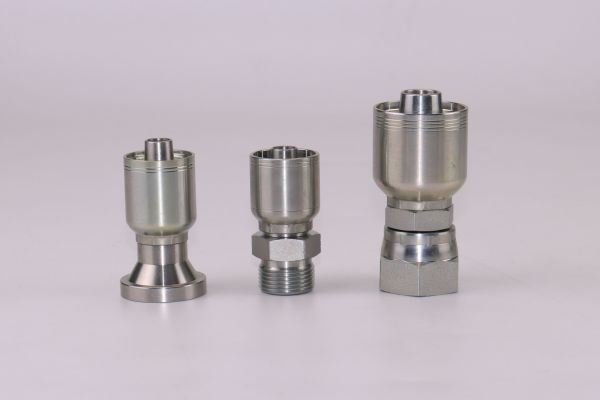
Parker reference Fitting

Protect the failed components and records

Remove components only under an approved procedure. Keep the fitting, hose section, mating adapter or port where relevant, seals, clamps, and debris associated with the event. Cap openings, avoid cleaning sealing faces, and do not cut through the suspected failure zone unless an agreed examination plan requires it.

Label each item with claim identifier, location in the assembly, removal orientation, and chain-of-custody information. Preserve machine logs, maintenance records, work orders, assembly travelers, crimp records, and earlier photos. Reworking the fitting, wiping the leak path, or discarding the hose can eliminate the evidence needed to distinguish product, assembly, installation, and application causes.

Verify Product Identity, Batch, and Assembly Configuration

An investigation cannot compare the assembly with requirements until it knows what was installed. Record the fitting part number, batch or lot, orientation, port connection, hose-side size, stem/ferrule series, markings, finish, and seal components. If a batch number is missing, document that limitation and search controlled purchase, receiving, and production records without inventing a match.

The hose record should include manufacturer, full series, construction, hose ID or dash size, and available lot information. Same dash size does not prove compatibility because hose OD, cover, reinforcement, and compression behavior may vary by series. Identify the exact approved hose-and-fitting combination and applicable revision.

Reconstruct the assembly process

Retrieve preparation instructions, skive or no-skive status, insertion control, crimp equipment, die set, target and measurement location, operator or station record, and inspection results. Do not infer an insertion depth or acceptable crimp diameter from another series. Use current or historically applicable approved data for the actual production date.

A one-piece fitting normally has a stem and ferrule preassembled, attached, or retained together, but this does not guarantee correct hose selection or crimping. Confirm that the returned components are the intended pair and look for evidence of unauthorized mixing, substitution, or rework.

When records conflict, preserve both versions and identify which source had authority at the time. A later drawing revision should not be applied retrospectively unless change control explicitly establishes that relationship.

Separate Connection-Side Evidence from Hose-Side Evidence

The leak location narrows hypotheses but does not assign responsibility. Connection-side leakage involves the port interface; hose-side leakage or pull-off involves the stem, ferrule, hose, preparation, insertion, and crimp relationship. Fluid can travel along surfaces and emerge away from its origin, so clean-path assumptions must be verified safely.

Connection-side branch

Inspect thread identity and condition, pitch or TPI, straight or tapered form, male or female arrangement, seat angle, sealing face, O-ring or other seal, mating component, alignment, and signs of cross-threading or repeated tightening. For ORFS, review the O-ring, groove, flat face, and mating face. For JIC, review both 37-degree flare surfaces and alignment. For tapered threads, use the specified sealing method and inspect thread damage.

Do not treat thread sealant as proof that the connection was correct. It cannot repair an incompatible standard, wrong seat, damaged face, incorrect O-ring, or cross-threading. A fitting that threads into a port may still have the wrong sealing interface.
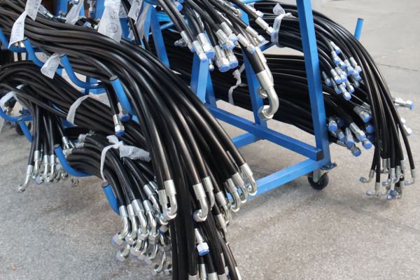
Crimping hydraulic hoses

Hose-side and crimp branch

Inspect the failure location relative to the ferrule, insertion evidence, hose cover, reinforcement, tube where safely exposed under an approved plan, ferrule deformation, stem condition, and signs of twist or bend near the fitting. Compare actual crimp measurements only with the approved data and measurement location for that exact combination.

An approximate outside measurement cannot prove internal engagement. Likewise, a hose pull-off does not automatically prove a defective fitting; it may involve incorrect hose series, preparation, insertion, crimp, tooling, component identity, or service loading. Each hypothesis needs evidence.

Reconstruct Fluid, Pressure, Temperature, and Installation

Product conformity and application suitability are related but separate questions. Record normal and abnormal pressure conditions, impulse or spikes where data exists, fluid identity and concentration, internal and ambient temperature, equipment duty, service duration, and maintenance events. Do not invent missing values from the machine category.

Pressure suitability is limited by the lowest-rated component in the complete assembly or circuit. The fitting, hose, adapter, port, coupling, and other components may have different limits. A product can match its drawing yet be unsuitable for an unapproved fluid, temperature, pressure cycle, or environment.

Examine the installed load path

Review hose length, bend radius, straight allowance near fittings, twist, clamps, abrasion, movement, external impact, heat, corrosion, and port alignment. A hose forced between misaligned ports can transmit side load and vibration into an otherwise correct connection. A hose that is too short may remain under tension; one that is too long may rub or kink.

Check installation and service history for component replacement, repeated disassembly, seal replacement, rerouting, tightening, pressure adjustments, contamination events, or impact. Record facts and source quality. A verbal recollection can guide questions but should not be treated as equivalent to a controlled maintenance record.

Classify Cause Families Through Branching Evidence

Cause classification should follow verified observations rather than a generic list. Begin with the failure location and ask which evidence supports or contradicts each branch. Maintain more than one live hypothesis until discriminating evidence is available.

Product or assembly branch

The product branch considers material, dimension, thread, sealing face, O-ring, plating, stem, ferrule, or manufacturing conformity against approved requirements. Evidence may include dimensional results, material records, batch comparison, and physical examination. A single damaged return may not represent the batch.

The assembly branch considers hose selection, preparation, insertion, fitting/ferrule identity, die, crimp target, crimp location, equipment condition, and inspection. A recorded setting supports the reconstruction but should be corroborated by the returned assembly and process controls where possible.
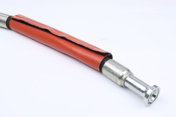
China hydraulic hoses assembly Topa

Installation, application, and handling branch

The installation branch considers alignment, tightening procedure, hose twist, elbow clocking, routing, clamps, bend, cleanliness, and damage during installation. The application branch considers pressure, impulse, temperature, fluid, vibration, movement, external environment, and equipment changes.

The handling branch covers transport, storage, corrosion exposure, damaged threads or faces, incorrect caps, contamination, and post-failure alteration. These conditions may predate installation or occur during return shipment, so chain-of-custody evidence matters.

Insufficient-evidence branch

Choose insufficient evidence when missing identity, records, mating parts, service data, or altered components prevent a supported conclusion. This differs from product defect not found, which indicates that defined examinations did not identify a product nonconformity within their scope. Neither conclusion proves another cause unless evidence supports it.

Decide Whether Further Testing Is Justified

Testing should answer a specific unresolved hypothesis and be capable of changing the decision. Do not order broad laboratory work simply to make the claim file look complete. Define the question, specimen, method, reference, limitations, destructive effects, and decision rule before testing.

Further examination may be justified when the physical evidence is preserved, the characteristic is relevant to the failure mode, and routine inspection cannot resolve it. Examples can include controlled dimensional review, material or coating analysis, seal evaluation, surface examination, or comparison with retained lot samples when the approved investigation plan requires them.

Protect against destructive sequencing errors

Perform nondestructive documentation and measurements before cutting, cleaning, sectioning, or otherwise altering the return. If several parties need access, agree on the examination sequence and retain representative material where practical. A destructive test that removes the suspected origin can prevent later independent review.

Testing is usually not justified when the sample identity cannot be established, damage occurred after the event, or the result would not distinguish the active hypotheses. State the limitation rather than presenting an expensive but irrelevant result as certainty.

Build the Claim File and Set the Responsibility Boundary

The final claim file should separate observed symptom, preserved evidence, verified facts, hypotheses, examinations, root-cause conclusion, containment, corrective action, and responsibility disposition. Avoid blending customer statements, investigator inference, and measured results into one narrative.

Before responsibility is assigned, confirm:

Assign responsibility only to the extent supported by the root cause and contractual framework. A confirmed product nonconformity may support product responsibility; a verified assembly or installation error supports a different disposition. Mixed causes may require shared corrective actions. Unknown evidence should remain unknown rather than being converted into blame.

Containment should be proportional and traceable. Identify affected lots or configurations, preserve safe operations, and review similar assemblies when evidence warrants it. Do not recall or clear unrelated products merely to appear decisive, and do not release potentially related stock while a material safety question remains unresolved.

Conclusion

A reliable claim investigation begins by preserving the assembly and separating symptoms from causes. Verify fitting, batch, hose series, preparation, insertion, crimp, mating connection, and service conditions before developing product, assembly, installation, application, or handling hypotheses. Use testing only when it can resolve a defined question, and protect evidence before destructive work. Missing records or altered returns may justify an insufficient-evidence conclusion; they do not justify an unsupported finding against either party. One-piece fitting warranty claim analysis should end with traceable facts, stated limitations, proportionate containment, corrective actions, and a responsibility decision no broader than the evidence. Record unresolved questions for future follow-up. Prepare the complete claim file and preserve the failed components before making commercial or technical commitments.

FAQ

Can a claim be investigated without a batch number?

Yes, but the missing batch limits traceability and may prevent a batch-level conclusion. Use controlled order and receiving records where available, and state any identity uncertainty explicitly.

What if hose and crimp records are missing?

Reconstruct available evidence from the returned assembly and controlled system records, but do not invent the setup. Missing combination or crimp data may require an insufficient-evidence disposition.

Does leak location prove which component failed?

No, fluid can travel and emerge away from its origin. Safely inspect the full connection, hose-side assembly, mating component, route, and service evidence before assigning a cause.

Can a damaged returned part still support analysis?

It may support limited observations if the post-event damage is documented and distinguishable. Cleaning, cutting, corrosion, or transport damage can prevent conclusions about the original failure condition.

When is laboratory testing needed for a fitting claim?

Use it when a preserved specimen and defined method can resolve a relevant hypothesis that routine inspection cannot. State the test’s scope and limitations, and document the item before destructive examination.
What One-Piece Fitting Product Data Each SKU Should Include

What One-Piece Fitting Product Data Each SKU Should Include

A part number and photo cannot control a fitting from quotation through repeat order. Reliable one-piece fitting product data for each SKU must let sales describe the item, engineering verify it, purchasing order it, receiving inspect it, and the warehouse pick it without translating an informal description. The record should separate identity from engineering evidence, connection-side data from hose-side assembly data, and technical fields from packaging fields. It also needs document revisions and effective dates so an old drawing does not remain active after a controlled change. This data architecture defines the minimum record, conditional fields, and advanced fields required to keep one SKU consistent across its lifecycle.

Follow One SKU from Quotation to Repeat Order

Each lifecycle step asks a different question of the same item. Quotation needs an unambiguous commercial description. Engineering needs thread, seal, hose side, dimensions, material, and documents. Purchasing needs the controlled order identity. Receiving needs inspection references, while warehouse and repeat-order teams need labels, quantities, revisions, and traceability.

Flange Fitting protection

The item master should therefore act as a routing record rather than a giant text note. It stores stable fields directly and links to controlled drawings, crimp data, inspection documents, packaging instructions, and revisions. A user should be able to move from the SKU to its evidence without searching email attachments.

Define a single owner and source for every field

Assign ownership by data group. Product-data staff may own descriptions and barcodes; engineering owns technical definitions; quality owns inspection and evidence status; operations owns packaging configuration; document control owns revisions. Where the same value appears in several systems, name one authoritative source and synchronize the others.

Avoid allowing quotation text to become the de facto specification. Sales descriptions are designed for readability and may omit critical details. They should be generated from or reconciled with controlled attributes rather than edited independently for each transaction.

Separate Identification Data from Engineering Data

Identification data answers “Which SKU is this?” Engineering data answers “What technical characteristics define it?” Mixing these functions into one description makes duplicates hard to detect and changes hard to control.

Identification fields include internal part number, external or supplier part number where applicable, normalized short description, product family, active status, unit of measure, barcode, and approved cross-references. They should resolve one code to one controlled item and packaging unit.

Engineering fields include connection geometry, hose-side family, controlled dimensions, material, finish, seals, drawing, and applicable assembly data. These fields should not be overwritten when a marketing description changes. If a technical change alters identity or interchangeability under the organization’s policy, route it through revision or new-SKU control rather than silently editing the description.

Control duplicate SKU risk

Duplicate records often begin with conflicting descriptions: one item says “JIC female,” another says “female swivel,” and a third uses only a cross-reference. Normalize terminology and compare structured fields before issuing a new code. A photo match or similar description should trigger review, not automatic merging.

When duplicates are confirmed, preserve transaction history and controlled cross-references. When two similar records differ technically, make the distinguishing fields visible in the short description or selection interface so quoting and picking do not collapse them back into one informal item.

Keep Connection-Side and Hose-Side Data Independent

The port end and hose end belong in separate field groups because they control different interfaces. A correct connection standard does not prove that the stem and ferrule suit the selected hose. A correct hose dash does not prove the thread or sealing face fits the equipment port.

43 series crimp fittings protection

Connection-side record

Store fitting orientation; male or female arrangement; connection standard; thread diameter and pitch or TPI; straight or tapered form; port dash; seat angle where applicable; sealing face; sealing method; O-ring location and controlled seal identity where applicable. For elbows, include orientation-relevant drawing information and critical geometry references.

Do not identify JIC, SAE flare, NPT, NPTF, BSPP, BSPT, ORFS, ORB, Metric, DIN, JIS, or flange connections from appearance alone. Similar threads can mate partially while seats or sealing methods remain incompatible. The structured record should retain the measurements and document basis used for identification.

Hose-side assembly record

Store hose dash, stem/ferrule fitting series, and the exact approved hose manufacturer or compatible controlled specification and series. Link preparation, skive or no-skive instruction, insertion control, crimp equipment, die, final crimp target, measurement location, and document revision where approved data requires them.

Dash size alone is insufficient because hose OD, cover, tube, and reinforcement can vary among series. A one-piece design keeps the stem and ferrule together, but it does not create universal hose compatibility. Missing hose-series data should place assembly approval on hold even if the catalog SKU can still be quoted conditionally.

Store Dimensions, Material, and Finish in Technical Records

Dimensions should be structured around operational decisions. A drawing remains the controlled geometry source, while selected searchable fields help users compare, inspect, and prevent interference. Store units explicitly and never combine nominal, tolerance, and measured values in one field.

Typical dimensional fields include overall or reference length, thread or flange dimensions, hex or wrench size, elbow centerline geometry, hose-tail references, and other critical dimensions named on the drawing. Do not invent universal dimensions or copy values from a visually similar size. Each field should link to the drawing revision that defines it.

Material and finish records should distinguish base material, surface finish or plating specification, and seal material. A generic “steel fitting” description does not control grade, coating, corrosion requirement, or evidence. Likewise, salt-spray duration should not be treated as a direct prediction of field life.

Weight needs units and status

Weight may support logistics, costing, and inventory planning, but it should include unit, basis, and status. Identify whether it is controlled, measured, or provisional. If weight is missing, do not invent it from a nearby SKU; flag the field and use a documented operational fallback until verified data is available.

Material and seal suitability still depend on fluid, temperature, corrosion exposure, regulations, and equipment requirements. Product data should state what is defined and link to evidence; it should not turn an item-master field into an unsupported application guarantee.

Use One Master Record with Grouped Fields

The following master structure keeps searchable values concise while preserving links to authoritative documents. “Conditional” means the field becomes mandatory when that feature or process applies.

Avoid turning the table into one free-text database column. Use controlled lists for standards, orientations, materials, and statuses; numeric fields should carry units; document fields should carry identifiers and revisions. Free text remains useful for limited exceptions and technical notes, but not for defining the primary identity.

Connect Logistics and Packaging to the Commercial Record

Commercial records should contain the data required to order, receive, store, count, and ship the SKU. This includes purchase and sales units, unit conversion where controlled, barcode, packaging level, pack quantity, carton quantity, carton dimensions or weight when verified and needed, label description, and handling requirements.

Packaging variants can require separate records when they change the sellable unit, barcode, brand, or contractual configuration. In other situations they may be controlled revisions under one SKU. Apply a documented item-governance rule rather than creating or merging codes case by case.

clear label

Make receiving able to reconcile the shipment

Receiving should be able to compare purchase order, part mark, unit label, carton label, packing list, quantity, and lot without opening unrelated systems. The record should also point to the current incoming-inspection plan and drawing revision. A carton with the correct brand but an old technical revision is not automatically acceptable.

Packaging data must not overwrite product data. A carton-quantity change may leave the fitting technically unchanged while still requiring label, ERP, warehouse, and effective-date updates. Preserve that distinction in revision history.

Control Revisions and Define Mandatory Fields

Drawing revision and data revision should be linked but not confused. A drawing can change while commercial packaging remains stable, or a label can change without altering geometry. The master record should show which documents changed, their effective date or lot, and the disposition of old stock and open orders.

Mandatory fields are those required to identify, order, receive, and technically distinguish every active SKU. Conditional fields become mandatory when the feature exists: O-ring data for an O-ring seal, elbow geometry for an elbow, skive instructions where preparation applies, or packaging variants where multiple sellable packs exist.

A minimum viable SKU record contains:

Optional advanced fields include verified individual weight, 3D model, structured critical dimensions, digital product classification, market-specific descriptions, serial tracking, and automated document-validity checks. Add them when a workflow consumes them; unused fields tend to become stale and create false confidence.

Product data does not independently prove application suitability. Pressure is limited by the lowest-rated component, and pressure impulse, fluid, temperature, routing, vibration, hose construction, and current crimp instructions may still need application-specific confirmation.

Review active records periodically for broken document links, obsolete statuses, duplicate descriptions, and conditional fields that became mandatory after a product or packaging change.

Conclusion

An effective SKU record lets every function identify the same fitting without relying on a photograph, memory, or old quotation. Separate identity from engineering evidence, keep connection-side and hose-side fields independent, and link dimensions, material, finish, seals, packaging, and documents to controlled revisions. Make core fields mandatory and feature-dependent fields conditional, then expose missing data instead of filling gaps with assumptions. Revision, effective-lot, and supersession controls prevent stale drawings or mixed packaging from becoming repeat-order errors. The minimum one-piece fitting product data for each SKU should support quotation, technical review, purchasing, receiving, scanning, picking, and traceability. Prepare the authoritative field owners, drawing links, assembly-data status, packaging configuration, and revision rules, and document unresolved fields before expanding the catalog.

FAQ

What should the record show when a fitting weight is missing?

Mark the value as missing or provisional and state the operational fallback. Do not copy weight from a nearby SKU; add the verified value later with unit, basis, and revision.

Can a SKU remain active when the approved hose series is unknown?

It may remain identifiable for catalog cleanup, but it should not be released for hose assembly as though compatibility were proven. Use an explicit hold or unapproved status until current combination data is available.

Which revision matters when the drawing and item master differ?

The controlled document hierarchy should define authority and require reconciliation before use. Hold the transaction or technical decision rather than choosing whichever revision is easiest to access.

Does a packaging change require new product data?

Yes, affected commercial and logistics fields need controlled updates even when the fitting is technically unchanged. Whether it creates a new SKU or a revision depends on the approved item-governance rule.

Can product photos replace dimensions and drawings?

No, photos can support screening, condition checks, and visual identification. They cannot prove thread geometry, seat, sealing method, critical dimensions, hose compatibility, or revision status.

How Ferrule Springback Affects Final Crimp Dimensions

How Ferrule Springback Affects Final Crimp Dimensions

Ferrule springback affects final crimp dimensions because the sleeve and compressed hose layers recover elastically after the dies open. Geometry under die load is therefore not identical to the relaxed diameter measured afterward. The ferrule also retains permanent deformation, so it does not return to its starting shape. Confusion arises when die size, machine setting, under-load geometry, and final measurement are treated as interchangeable numbers. They describe different stages or locations in the process.

Die-closed and post-release geometry are different states

The dies define a loaded boundary while they are closed; the inspection tool reads a relaxed component after that boundary has been removed. A difference between those states is physically expected and must be handled through approved crimp data, not operator guesswork.

Under load, the ferrule is pressed inward by the die segments while the hose stack reacts from inside. Metal strain contains both elastic and plastic components. Hose cover, reinforcement, and inner tube are also compressed and store recoverable energy. The measured result after release reflects how all of these parts settle together.

Springback is often discussed as though only the ferrule moves outward. In practice, elastomer recovery and reinforcement response can push against the sleeve while the ferrule’s own elastic strain relaxes. The final diameter is therefore a system outcome for one exact hose, fitting, ferrule, and crimp procedure.

This distinction matters during troubleshooting. Comparing a die designation directly with a final outside diameter can create a false discrepancy because the values may refer to different physical surfaces, states, or calibration conventions.

Before Crimping: Starting Geometry Sets the Deformation Path

Springback cannot be interpreted without knowing the starting condition. Ferrule dimensions, wall distribution, material state, hose construction, insertion, and component temperature influence the route taken toward the final shape.

Before closure, the ferrule has its manufactured outside and inside geometry. The hose cover, reinforcement, and tube retain their uncompressed layer relationships around the inserted stem. Clearances and interference are determined by the exact component combination, not by dash size alone.

measure hose Ferrule Length

Starting components determine the path

Two assemblies can target the same nominal final diameter yet begin with different ferrule wall thicknesses, hose cover dimensions, reinforcement arrangements, or stem profiles. They may therefore require different deformation paths and store different elastic energy under load. Matching final numbers does not prove that their processes or compatibility are equivalent.

One assembly might reach the target after a relatively small ferrule reduction around a thicker internal stack, while another might require more sleeve movement around a different construction. That comparison does not rank either design; it shows why the final number is an endpoint rather than a history. Only the approved starting components and process records reveal which deformation path was intended.

Record part identities and starting measurements when an investigation calls for them. Do not substitute an untraceable sleeve or a hose from another series merely because the initial outside sizes appear similar.

Under Load: Elastic and Plastic Deformation Coexist

As the dies close, the ferrule first responds largely elastically and then undergoes permanent plastic deformation. Both responses remain present at the die-closed condition, which is why part of the movement is retained and part is recovered.

Elastic deformation is the recoverable change associated with applied load. Plastic deformation is the lasting shape change that remains after load removal. A finished crimp requires controlled permanent deformation; if the ferrule recovered completely, the assembly would return toward its starting state.

Recoverable and permanent change

The proportion and distribution of these responses are not uniform across every ferrule. Wall geometry, transitions, material condition, die contact, and internal support affect local strain. A sleeve may experience different states near the center of the crimp zone and near a front or rear transition.

Machine display values do not reveal that local distribution. They may indicate a programmed target, correction, tool position, or another equipment-specific parameter. The display should be interpreted using the machine manufacturer’s documentation and the approved assembly specification.

After Release: Recovery Produces the Final Measured State

When the dies open, contact load decreases and recoverable strain begins to relax. Ferrule metal moves slightly from its loaded boundary, and the hose layers rebound against their remaining constraints until the joint reaches a post-release state.

Some recovery occurs immediately, while additional settling may be influenced by temperature and viscoelastic behavior of hose materials. This does not justify inventing a universal waiting time. Measurement timing should follow the applicable procedure and be recorded when investigating a discrepancy.

Crimping Compatibility & Safety Reminder

Final geometry settles after unloading

The ferrule’s final outside shape can reflect die segmentation, initial eccentricity, material variation, and internal hose response. Measuring one orientation may miss the largest or smallest diameter. Where the procedure requires it, take measurements at defined axial locations and orientations and report roundness evidence rather than averaging away a meaningful difference.

Springback is not a defect by definition. It is a normal unloading response that the validated crimp specification accounts for. The problem occurs when teams compare unlike data or try to compensate outside approved limits.

Keep Crimp Terms and Data Types Separate

Clear terminology prevents a machine input from being mistaken for an acceptance measurement. Every value should be labeled by physical meaning, reference surface, process state, and location.

Label every value by state and location

An investigation should preserve the original labels rather than placing every number in one “crimp diameter” column. Drawing references and specification revisions are needed because the same term may be used differently across systems.

Hose Layers Influence the Relaxed Ferrule State

The ferrule is recovering against a compressed internal stack, not in free air. Hose cover, reinforcement, inner tube, and stem support influence where the sleeve settles after release.

Cover compounds can recover differently, and reinforcement constructions can react differently to circumferential reduction. The stem defines the internal boundary and changes local support along its serrations and transitions. Skive and no-skive preparations also place different material arrangements beneath the ferrule.

These interactions explain why a springback allowance from one hose family cannot be transferred automatically to another. Even the same nominal hose size can use different wall construction and reinforcement. Fitting series, ferrule geometry, and crimp-zone length add further variables.

Do not interpret a larger post-release diameter as proof of weak metal or a smaller one as proof of better retention. Both are measurements requiring comparison with the correct approved range and process evidence. Retention, pressure, and impulse performance need their own validation.

Multi-Layer Hydraulic hoses

Material and geometry change recovery without a fixed offset

Springback can vary with material condition and ferrule geometry, but it should not be reduced to one percentage or correction value. Such a shortcut hides the system variables and encourages unsafe manual compensation.

Different alloys or material conditions can have different elastic and plastic responses. Wall thickness, eccentricity, grooves, transitions, and local section changes affect stiffness and strain distribution. Surface treatment can also influence measurement or reveal deformation without serving as a direct predictor of recovery.

Geometry matters along the ferrule as well as around its circumference. The principal crimp region may settle differently from a bell mouth or attachment transition. A measurement near an edge cannot be substituted for the specified central location unless the procedure explicitly permits it.

If a material, ferrule, or hose change is proposed, treat it as an assembly change. Review controlled compatibility and validation requirements instead of applying a historic offset from another part family.

Calibration and Measurement Variation Can Mimic Springback

Not every difference between expected and recorded diameter is caused by material recovery. Machine calibration, die wear or contamination, instrument error, method variation, temperature, location, and roundness can produce or amplify apparent discrepancies.

Check that the correct die is installed and clean, the machine calibration is current, and the approved program and correction are selected. Verify that the measuring instrument is suitable, in calibration, and used with the defined contact orientation and force. Record who measured, where, when, and at what part condition.

Rule out equipment and gauge variation

Warm parts can differ from parts at a later stable temperature due to thermal expansion and hose-material behavior. This does not create a universal rule to cool every part for a fixed time. Follow the approved measurement procedure and keep timing and temperature consistent enough for valid comparison.

Gauge repeatability and operator technique should be considered before changing the crimp process. A measurement-system study may be appropriate when repeated readings vary enough to obscure the actual part response. Never “chase” noisy readings by progressively over-crimping.

Separate repeatability from reproducibility during this review. Repeatability asks whether one inspector and instrument obtain consistent readings at the same defined location. Reproducibility asks whether different inspectors, instruments, or shifts agree when following the same method. If either is poor, the apparent change assigned to springback may actually be measurement variation. Resolve that evidence gap before interpreting small differences in relaxed geometry.

Compare Unexpected Final Dimensions Systematically

Troubleshooting should move from data identity to equipment and measurement, then to components and material response. This order keeps springback from becoming a catch-all explanation.

First label each value: die designation, machine command, loaded observation if available, final measured diameter, axial location, orientation, timing, and instrument. Confirm the drawing, crimp specification, program, and revision belong to the exact hose and fitting combination.

Compare data in a fixed order

Next verify machine calibration, die identity and condition, axial positioning, insertion, and measurement system. Repeat only the measurements allowed by the procedure; do not re-crimp the assembly. Compare multiple traceable samples to see whether the difference is systematic or isolated.

Then review ferrule starting geometry, material and lot records, hose construction, stem and ferrule identity, and section evidence if a controlled destructive plan is justified. Compare findings with approved limits and validation data. Any process adjustment must remain within authorized instructions and be approved by the responsible technical authority.

Conclusion

Ferrule springback is the recoverable part of a larger deformation process. Before crimping, component geometry defines the path; under load, elastic and plastic strains coexist; after release, metal and hose layers settle into the final measured state. Die size, machine setting, loaded geometry, final diameter, and measurement location are therefore different data types. Material and geometry influence recovery, but no fixed offset applies to every assembly, and calibration or measurement variation can imitate springback. When reviewing ferrule springback final crimp dimensions, identify every value by state and location, confirm exact hose and fitting data, verify tooling and calibration, record timing and roundness, and use only approved procedures for any adjustment.

FAQ

Should final crimp diameter be measured immediately after release?

Follow the timing defined by the approved procedure. Immediate and later measurements may differ, so investigation records should state when the value was taken.

Can a warm ferrule show a different final diameter?

Yes, temperature can affect metal dimensions and hose-material response. Use the specified measurement condition rather than applying an invented temperature correction.

Do different ferrule materials have the same springback?

Not necessarily, because material condition and geometry influence elastic recovery. Any material change requires controlled engineering review and applicable validation.

Is the machine display the final crimp diameter?

Not necessarily, because the display may represent a target, tool position, or equipment-specific correction. Compare it with machine documentation and the approved measurement method.

Can operators over-crimp to cancel springback?

No, manual over-crimping outside approved data can damage the hose, reinforcement, ferrule, or stem relationship. Any authorized correction must remain within validated procedures.

Contact Topa

Save 30% on maintenance costs with our easy-install hydraulic fittings. Contact Now!