Ferrule springback affects final crimp dimensions because the sleeve and compressed hose layers recover elastically after the dies open. Geometry under die load is therefore not identical to the relaxed diameter measured afterward. The ferrule also retains permanent deformation, so it does not return to its starting shape. Confusion arises when die size, machine setting, under-load geometry, and final measurement are treated as interchangeable numbers. They describe different stages or locations in the process.
Die-closed and post-release geometry are different states
The dies define a loaded boundary while they are closed; the inspection tool reads a relaxed component after that boundary has been removed. A difference between those states is physically expected and must be handled through approved crimp data, not operator guesswork.
Under load, the ferrule is pressed inward by the die segments while the hose stack reacts from inside. Metal strain contains both elastic and plastic components. Hose cover, reinforcement, and inner tube are also compressed and store recoverable energy. The measured result after release reflects how all of these parts settle together.
Springback is often discussed as though only the ferrule moves outward. In practice, elastomer recovery and reinforcement response can push against the sleeve while the ferrule’s own elastic strain relaxes. The final diameter is therefore a system outcome for one exact hose, fitting, ferrule, and crimp procedure.
This distinction matters during troubleshooting. Comparing a die designation directly with a final outside diameter can create a false discrepancy because the values may refer to different physical surfaces, states, or calibration conventions.
Before Crimping: Starting Geometry Sets the Deformation Path
Springback cannot be interpreted without knowing the starting condition. Ferrule dimensions, wall distribution, material state, hose construction, insertion, and component temperature influence the route taken toward the final shape.
Before closure, the ferrule has its manufactured outside and inside geometry. The hose cover, reinforcement, and tube retain their uncompressed layer relationships around the inserted stem. Clearances and interference are determined by the exact component combination, not by dash size alone.
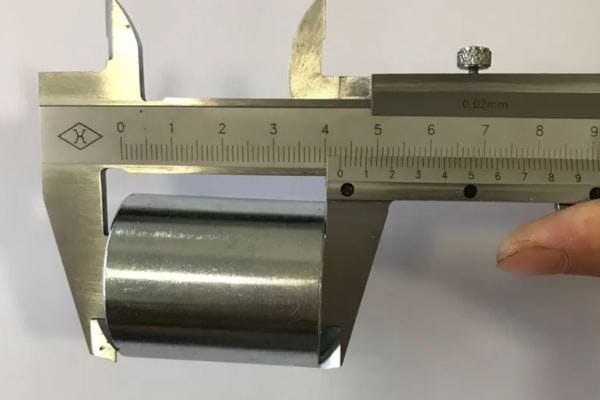
Starting components determine the path
Two assemblies can target the same nominal final diameter yet begin with different ferrule wall thicknesses, hose cover dimensions, reinforcement arrangements, or stem profiles. They may therefore require different deformation paths and store different elastic energy under load. Matching final numbers does not prove that their processes or compatibility are equivalent.
One assembly might reach the target after a relatively small ferrule reduction around a thicker internal stack, while another might require more sleeve movement around a different construction. That comparison does not rank either design; it shows why the final number is an endpoint rather than a history. Only the approved starting components and process records reveal which deformation path was intended.
Record part identities and starting measurements when an investigation calls for them. Do not substitute an untraceable sleeve or a hose from another series merely because the initial outside sizes appear similar.
Under Load: Elastic and Plastic Deformation Coexist
As the dies close, the ferrule first responds largely elastically and then undergoes permanent plastic deformation. Both responses remain present at the die-closed condition, which is why part of the movement is retained and part is recovered.
Elastic deformation is the recoverable change associated with applied load. Plastic deformation is the lasting shape change that remains after load removal. A finished crimp requires controlled permanent deformation; if the ferrule recovered completely, the assembly would return toward its starting state.
Recoverable and permanent change
The proportion and distribution of these responses are not uniform across every ferrule. Wall geometry, transitions, material condition, die contact, and internal support affect local strain. A sleeve may experience different states near the center of the crimp zone and near a front or rear transition.
Machine display values do not reveal that local distribution. They may indicate a programmed target, correction, tool position, or another equipment-specific parameter. The display should be interpreted using the machine manufacturer’s documentation and the approved assembly specification.
After Release: Recovery Produces the Final Measured State
When the dies open, contact load decreases and recoverable strain begins to relax. Ferrule metal moves slightly from its loaded boundary, and the hose layers rebound against their remaining constraints until the joint reaches a post-release state.
Some recovery occurs immediately, while additional settling may be influenced by temperature and viscoelastic behavior of hose materials. This does not justify inventing a universal waiting time. Measurement timing should follow the applicable procedure and be recorded when investigating a discrepancy.
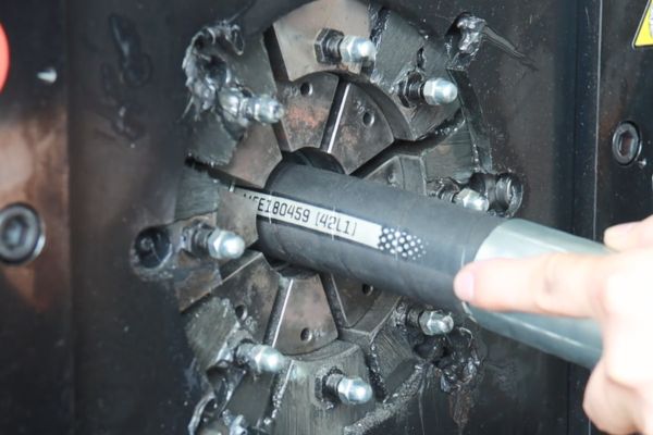
Final geometry settles after unloading
The ferrule’s final outside shape can reflect die segmentation, initial eccentricity, material variation, and internal hose response. Measuring one orientation may miss the largest or smallest diameter. Where the procedure requires it, take measurements at defined axial locations and orientations and report roundness evidence rather than averaging away a meaningful difference.
Springback is not a defect by definition. It is a normal unloading response that the validated crimp specification accounts for. The problem occurs when teams compare unlike data or try to compensate outside approved limits.
Keep Crimp Terms and Data Types Separate
Clear terminology prevents a machine input from being mistaken for an acceptance measurement. Every value should be labeled by physical meaning, reference surface, process state, and location.
| Term | What it describes | Why it is not interchangeable |
| Die size | Tool geometry or designation defined by the equipment system | It may not equal the ferrule diameter and does not include the whole deformation response |
| Machine setting | Command, target, or correction interpreted by a specific machine | Display logic is equipment-specific and may not represent a directly measured surface |
| Under-load diameter | Ferrule geometry while constrained by closed dies | It includes elastic deformation that changes after unloading |
| Final crimp diameter | Relaxed ferrule size measured by the approved method | It depends on release, timing, location, orientation, and the complete assembly |
| Measurement location | Defined axial and circumferential position of inspection | Different locations may have transitions or different roundness |
Label every value by state and location
An investigation should preserve the original labels rather than placing every number in one “crimp diameter” column. Drawing references and specification revisions are needed because the same term may be used differently across systems.
Hose Layers Influence the Relaxed Ferrule State
The ferrule is recovering against a compressed internal stack, not in free air. Hose cover, reinforcement, inner tube, and stem support influence where the sleeve settles after release.
Cover compounds can recover differently, and reinforcement constructions can react differently to circumferential reduction. The stem defines the internal boundary and changes local support along its serrations and transitions. Skive and no-skive preparations also place different material arrangements beneath the ferrule.
These interactions explain why a springback allowance from one hose family cannot be transferred automatically to another. Even the same nominal hose size can use different wall construction and reinforcement. Fitting series, ferrule geometry, and crimp-zone length add further variables.
Do not interpret a larger post-release diameter as proof of weak metal or a smaller one as proof of better retention. Both are measurements requiring comparison with the correct approved range and process evidence. Retention, pressure, and impulse performance need their own validation.
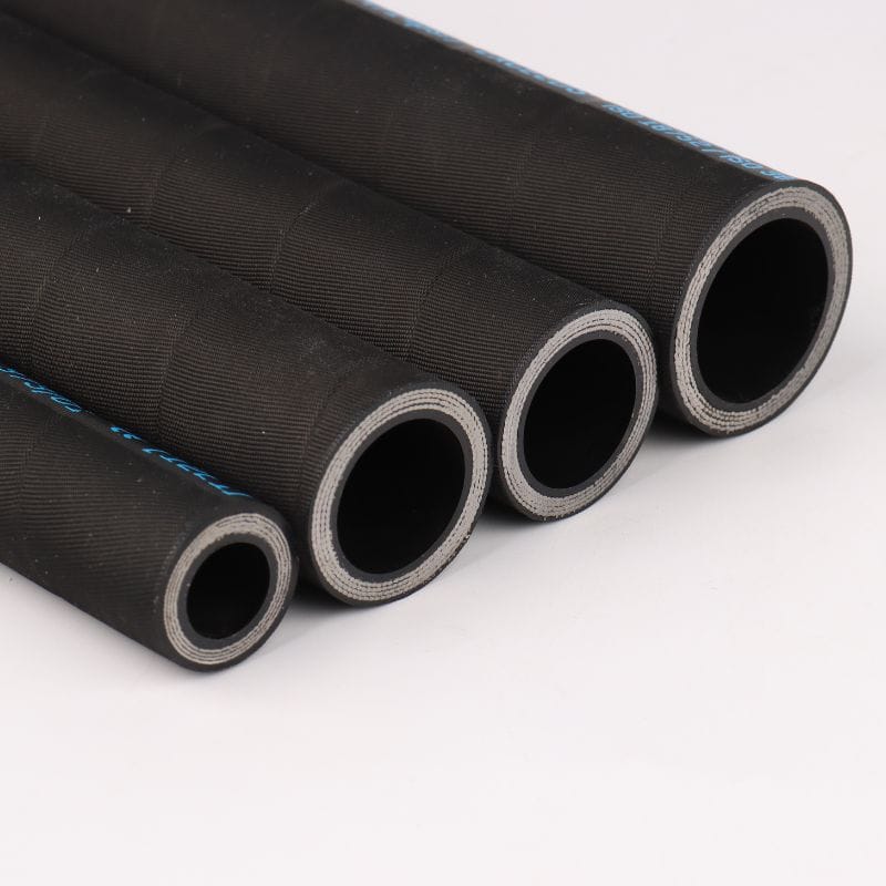
Material and geometry change recovery without a fixed offset
Springback can vary with material condition and ferrule geometry, but it should not be reduced to one percentage or correction value. Such a shortcut hides the system variables and encourages unsafe manual compensation.
Different alloys or material conditions can have different elastic and plastic responses. Wall thickness, eccentricity, grooves, transitions, and local section changes affect stiffness and strain distribution. Surface treatment can also influence measurement or reveal deformation without serving as a direct predictor of recovery.
Geometry matters along the ferrule as well as around its circumference. The principal crimp region may settle differently from a bell mouth or attachment transition. A measurement near an edge cannot be substituted for the specified central location unless the procedure explicitly permits it.
If a material, ferrule, or hose change is proposed, treat it as an assembly change. Review controlled compatibility and validation requirements instead of applying a historic offset from another part family.
Calibration and Measurement Variation Can Mimic Springback
Not every difference between expected and recorded diameter is caused by material recovery. Machine calibration, die wear or contamination, instrument error, method variation, temperature, location, and roundness can produce or amplify apparent discrepancies.
Check that the correct die is installed and clean, the machine calibration is current, and the approved program and correction are selected. Verify that the measuring instrument is suitable, in calibration, and used with the defined contact orientation and force. Record who measured, where, when, and at what part condition.
Rule out equipment and gauge variation
Warm parts can differ from parts at a later stable temperature due to thermal expansion and hose-material behavior. This does not create a universal rule to cool every part for a fixed time. Follow the approved measurement procedure and keep timing and temperature consistent enough for valid comparison.
Gauge repeatability and operator technique should be considered before changing the crimp process. A measurement-system study may be appropriate when repeated readings vary enough to obscure the actual part response. Never “chase” noisy readings by progressively over-crimping.
Separate repeatability from reproducibility during this review. Repeatability asks whether one inspector and instrument obtain consistent readings at the same defined location. Reproducibility asks whether different inspectors, instruments, or shifts agree when following the same method. If either is poor, the apparent change assigned to springback may actually be measurement variation. Resolve that evidence gap before interpreting small differences in relaxed geometry.
Compare Unexpected Final Dimensions Systematically
Troubleshooting should move from data identity to equipment and measurement, then to components and material response. This order keeps springback from becoming a catch-all explanation.
First label each value: die designation, machine command, loaded observation if available, final measured diameter, axial location, orientation, timing, and instrument. Confirm the drawing, crimp specification, program, and revision belong to the exact hose and fitting combination.
Compare data in a fixed order
Next verify machine calibration, die identity and condition, axial positioning, insertion, and measurement system. Repeat only the measurements allowed by the procedure; do not re-crimp the assembly. Compare multiple traceable samples to see whether the difference is systematic or isolated.
Then review ferrule starting geometry, material and lot records, hose construction, stem and ferrule identity, and section evidence if a controlled destructive plan is justified. Compare findings with approved limits and validation data. Any process adjustment must remain within authorized instructions and be approved by the responsible technical authority.
Conclusion
Ferrule springback is the recoverable part of a larger deformation process. Before crimping, component geometry defines the path; under load, elastic and plastic strains coexist; after release, metal and hose layers settle into the final measured state. Die size, machine setting, loaded geometry, final diameter, and measurement location are therefore different data types. Material and geometry influence recovery, but no fixed offset applies to every assembly, and calibration or measurement variation can imitate springback. When reviewing ferrule springback final crimp dimensions, identify every value by state and location, confirm exact hose and fitting data, verify tooling and calibration, record timing and roundness, and use only approved procedures for any adjustment.
FAQ
Should final crimp diameter be measured immediately after release?
Follow the timing defined by the approved procedure. Immediate and later measurements may differ, so investigation records should state when the value was taken.
Can a warm ferrule show a different final diameter?
Yes, temperature can affect metal dimensions and hose-material response. Use the specified measurement condition rather than applying an invented temperature correction.
Do different ferrule materials have the same springback?
Not necessarily, because material condition and geometry influence elastic recovery. Any material change requires controlled engineering review and applicable validation.
Is the machine display the final crimp diameter?
Not necessarily, because the display may represent a target, tool position, or equipment-specific correction. Compare it with machine documentation and the approved measurement method.
Can operators over-crimp to cancel springback?
No, manual over-crimping outside approved data can damage the hose, reinforcement, ferrule, or stem relationship. Any authorized correction must remain within validated procedures.