M, G, ZG, PT, NPT, NPSC, and UN do not describe the same thread system. They can differ in measurement units, thread angle, pitch, taper, tolerance, and sealing method. Two fittings with similar diameters may even screw together for several turns without being compatible. Correct identification requires more than measuring the outside diameter: the applicable standard, pitch, male or female form, taper, and actual sealing interface must all be confirmed.
Fastening Threads and Pipe Threads Are Not the Same
Fastening threads mainly provide mechanical force
M and UN are primarily fastening thread systems. Their main purpose is to connect mechanical components and generate clamping force.
The two common groups are:
M: ISO metric screw thread
UN: Unified inch screw thread
Neither system should automatically be treated as a pressure-sealing thread. A bolt with an M or UN thread normally relies on other components if fluid sealing is required.
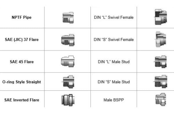
Hydraulic fittings may also use M or UN threads. In these cases, the thread usually provides the force that holds the connection together, while sealing is created by another feature, such as:
- An O-ring
- A 24-degree cone
- A 37-degree flare
- A 45-degree flare
- A flat face
- A bonded seal
- A metal-to-metal seat
This distinction is important because two fittings can have matching threads but incompatible sealing surfaces.
Pipe threads may or may not seal on the threads
Pipe thread systems include G, R, Rc, Rp, NPT, and NPSC. However, the phrase “pipe thread” does not necessarily mean that pressure sealing occurs between the threads.
For example, G is a parallel pipe thread. The threads provide mechanical engagement, while sealing normally occurs through a washer, O-ring, gasket, or machined face outside the threads.
R, Rc, and NPT are associated with tapered pipe-thread connections, where thread interference contributes to sealing. Even then, an appropriate sealant may still be necessary, depending on the thread system, fluid, temperature, and component specification.
The first identification question should therefore be:
Does this connection seal on the threads, or does it seal on a separate face, cone, flare, or O-ring?
M: ISO Metric Screw Threads
How metric threads are designated
M is the designation for ISO general-purpose metric screw threads. Dimensions are stated in millimeters.
For example:
M20 × 1.5
This means:
M: metric screw thread
20: nominal major diameter of 20 mm
1.5: pitch of 1.5 mm
The pitch is the axial distance from one thread crest to the next. Metric threads use a 60-degree basic thread angle and are normally parallel rather than tapered.
ISO 261 defines the general diameter-and-pitch plan for ISO metric threads, while ISO 68-1 defines the basic and design profiles. ISO 261 was confirmed as current in 2024, and the profile is covered by ISO 68-1:2023.
Coarse and fine metric pitches
If the pitch is omitted, the designation commonly refers to the standard coarse pitch for that diameter. In purchasing documents, however, the pitch should be written explicitly whenever misidentification is possible.
| Metric size | Common coarse pitch | Common fine-pitch examples |
| M8 | 1.25 mm | 1.0 mm |
| M10 | 1.5 mm | 1.25 or 1.0 mm |
| M12 | 1.75 mm | 1.5 or 1.25 mm |
| M14 | 2.0 mm | 1.5 mm |
| M16 | 2.0 mm | 1.5 mm |
| M18 | 2.5 mm | 2.0 or 1.5 mm |
| M20 | 2.5 mm | 2.0 or 1.5 mm |
| M22 | 2.5 mm | 2.0 or 1.5 mm |
| M24 | 3.0 mm | 2.0 or 1.5 mm |
An M20 × 2.5 component will not correctly mate with an M20 × 1.5 component, even though both have approximately the same major diameter.
For hydraulic connections, identifying the metric thread is only the first step. The buyer must also determine whether the fitting uses a 24-degree cone, an O-ring, a flat face, or another sealing method.
UN: Unified Inch Screw Threads
Understanding UNC, UNF, and UNEF
UN means Unified Inch Screw Thread. It uses inch-based diameters and states pitch as the number of threads per inch, or TPI.
The main series include:
UNC: Unified National Coarse
UNF: Unified National Fine
UNEF: Unified National Extra Fine
UNS: Unified National Special
A designation such as:
1/2-20 UNF
means that the thread has a nominal diameter of 1/2 inch, 20 threads per inch, and belongs to the UNF series.

UN threads use a 60-degree thread angle and are normally parallel. Their thread form, series, classes, allowances, tolerances, and designations are covered by ASME B1.1-2024.
Common UNC and UNF sizes
| Nominal size | UNC | UNF |
| 1/4 inch | 20 TPI | 28 TPI |
| 5/16 inch | 18 TPI | 24 TPI |
| 3/8 inch | 16 TPI | 24 TPI |
| 7/16 inch | 14 TPI | 20 TPI |
| 1/2 inch | 13 TPI | 20 TPI |
| 5/8 inch | 11 TPI | 18 TPI |
| 3/4 inch | 10 TPI | 16 TPI |
| 7/8 inch | 9 TPI | 14 TPI |
| 1 inch | 8 TPI | 12 TPI |
UNF threads are widely used on hydraulic fittings, including JIC 37-degree flare and SAE O-ring boss connections.
However, a matching UNF thread does not make JIC and SAE O-ring boss fittings interchangeable. A JIC connection seals on a 37-degree flare. An SAE O-ring boss connection seals with an O-ring installed near the thread shoulder.
Thread compatibility and sealing compatibility are separate questions.
G: Parallel Pipe Threads That Do Not Seal on the Threads
Characteristics of G threads
G belongs to the ISO 228 pipe-thread system and is commonly called BSPP, meaning British Standard Pipe Parallel.
Its main characteristics are:
- Parallel internal and external threads
- 55-degree thread angle
- Rounded Whitworth-type thread profile
- Size designation based on nominal pipe size
- Mechanical engagement through the threads
- Pressure sealing outside the threads
ISO 228-1 specifically covers pipe threads where pressure-tight joints are not made on the threads. It states that pressure sealing should be produced by tightening surfaces outside the threads with a suitable seal between them.
This means that G1/2 does not describe a self-sealing thread connection.
Why G1/2 does not measure 1/2 inch
Pipe-thread size is nominal. It originated from historical pipe-bore and pipe-series conventions rather than the measured outside diameter of the thread.
A G1/2 external thread has a basic major diameter of approximately 20.96 mm, not 12.7 mm.
Common sealing arrangements for G threads include:
- Bonded sealing washers
- Copper washers
- Flat gaskets
- O-rings
- Port-face seals
- Other component-specific sealing faces
Parker’s BSPP guidance similarly explains that the parallel thread provides holding force while a bonded washer, gasket, or O-ring creates the seal.
If a G fitting has no compatible sealing face or seal, tightening the threads more firmly may not stop leakage.
R, Rc, Rp, ZG, PT, and PF Threads
Modern ISO designations: R, Rc, and Rp
ISO 7-1 covers pipe threads intended to create pressure-tight joints on the threads. The commonly used designations are:
- R: tapered external thread
- Rc: tapered internal thread
- Rp: parallel internal thread intended to mate with an R external thread
The common combinations are:
- R external with Rc internal: tapered-to-tapered
- R external with Rp internal: tapered-to-parallel
These threads use a 55-degree profile. The tapered forms have a nominal 1:16 taper. Their dimensions, tolerances, and designations are covered by ISO 7-1.
Rp must not be confused with G. Both are parallel internal threads, but they belong to different functional systems and can have different tolerance requirements. Rp is intended to participate in a pressure-tight joint with a tapered R external thread. G is an ISO 228 fastening pipe thread that seals outside the threads.
Legacy names: ZG, PT, and PF
ZG is an older Chinese drawing designation or market term commonly associated with a British-type tapered sealing pipe thread. It is unsuitable as a complete modern specification because it may not clearly identify whether the part has an internal or external thread.
A drawing or purchase order should use R, Rc, or Rp and include the applicable standard.
PT and PF are older Japanese designations:
- PT generally corresponds to the earlier Japanese tapered sealing pipe-thread system.
- PF generally corresponds to the earlier Japanese parallel fastening pipe-thread system.
Before replacing one with another, verify:
- Nominal size
- Male or female form
- Standard edition
- Thread tolerance
- Effective engagement length
- Applicable gauges
- Sealing face
- Component pressure rating
Dimensional correspondence between thread standards does not automatically prove that complete fittings are functionally interchangeable.
NPT and NPSC Pipe Threads
NPT: American tapered pipe thread
NPT means National Pipe Taper. It is an American tapered pipe-thread system covered by ASME B1.20.1.
Its principal characteristics include:
- Tapered internal and external threads
- 60-degree thread angle
- Nominal 1:16 taper
- Inch-based pipe-size designation
- Thread interference that contributes to sealing
- Typical use with an appropriate thread sealant
The ASME B1.20.1 standard covers NPT, NPSC, NPSM, NPTR, and NPSL threads.
NPT should not be confused with NPTF. NPTF is a Dryseal thread controlled by ASME B1.20.3. It uses modified crest-and-root relationships intended to reduce spiral leakage without requiring sealing compound when correctly manufactured and assembled.
NPT and NPTF should not be treated as identical specifications.
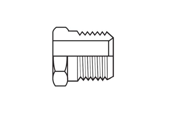
NPSC: American straight internal coupling thread
NPSC is a straight internal pipe thread within the ASME B1.20.1 system. The “C” refers to coupling.
It is mainly associated with specific coupling applications and is intended for use with a corresponding tapered external thread under the applicable component requirements.
NPSC is not a generic parallel version of NPT and should not be confused with NPSM. Although both NPSC and NPSM are straight pipe threads, their purposes and tolerance arrangements are not identical.
An order stating only “straight American pipe thread” is incomplete. It should identify NPSC, NPSM, or another applicable series, together with the mating component and sealing method.
BSP and NPT Pipe-Thread Size Chart
Common reference dimensions
The following table is intended for preliminary identification. Tapered-thread measurements vary with measurement position, wear, coating, and manufacturing tolerance. The figures must not replace calibrated gauges or the controlling standard.
| Nominal size | G/R basic major diameter | G/R pitch | NPT basic major diameter | NPT pitch |
| 1/8 | 9.73 mm | 28 TPI | 10.29 mm | 27 TPI |
| 1/4 | 13.16 mm | 19 TPI | 13.72 mm | 18 TPI |
| 3/8 | 16.66 mm | 19 TPI | 17.15 mm | 18 TPI |
| 1/2 | 20.96 mm | 14 TPI | 21.34 mm | 14 TPI |
| 3/4 | 26.44 mm | 14 TPI | 26.67 mm | 14 TPI |
| 1 | 33.25 mm | 11 TPI | 33.40 mm | 11.5 TPI |
| 1 1/4 | 41.91 mm | 11 TPI | 42.16 mm | 11.5 TPI |
| 1 1/2 | 47.80 mm | 11 TPI | 48.26 mm | 11.5 TPI |
| 2 | 59.61 mm | 11 TPI | 60.33 mm | 11.5 TPI |
The table shows why outside diameter alone is unreliable. A 1-inch R thread and a 1-inch NPT thread have very similar basic diameters, but their thread angles and pitches differ.
Why NPT and R cannot be mixed
NPT and R threads are both tapered at approximately 1:16, but that does not make them compatible.
| Feature | NPT | R/Rc |
| Standard | ASME B1.20.1 | ISO 7-1 |
| Thread angle | 60° | 55° |
| Profile | American pipe-thread form | Whitworth-type pipe-thread form |
| Typical pitches | 27, 18, 14, 11.5 TPI | 28, 19, 14, 11 TPI |
| Direct interchange | No | No |
At certain sizes, an NPT fitting may enter an R or Rc port for several turns. This is not evidence of compatibility. Forced assembly can deform the threads, create an unreliable contact pattern, reduce engagement, and produce a leak path.
How to Identify an Unknown Thread
Measure the thread in a controlled sequence
A practical identification process should follow these steps:
- Determine whether the thread is parallel or tapered.
- Measure the male major diameter or female opening.
- Measure the pitch in millimeters or threads per inch.
- Determine whether the profile is approximately 55 or 60 degrees.
- Identify whether the component is male or female.
- Inspect the end connection and sealing surface.
- Compare the results with the relevant standard table.
- Confirm with an appropriate thread gauge when safety or pressure is important.
To identify taper, measure the thread diameter at two positions along its length. A meaningful change suggests a tapered thread. A nearly constant diameter suggests a parallel thread.
Parker recommends determining taper, pitch, and size separately because choosing the wrong thread can damage the connection and compromise pressure-holding and sealing performance.
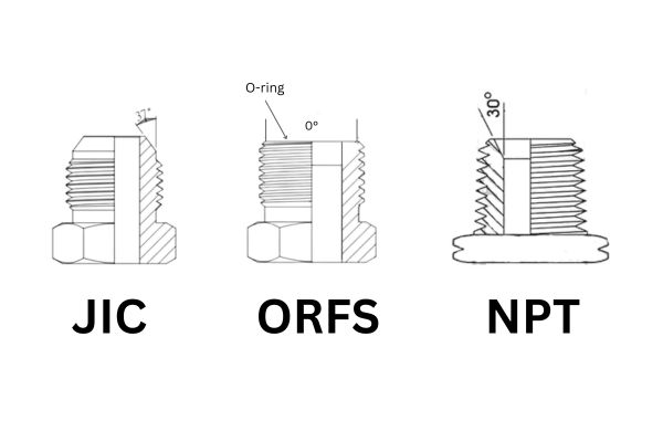
Identify the sealing surface before ordering
After identifying the thread, inspect where the connection actually seals.
Possible sealing locations include:
- The tapered threads
- A 37-degree flare
- A 45-degree flare
- A 24-degree cone
- A 30-degree seat
- A 60-degree cone
- A face O-ring
- A thread-adjacent O-ring
- A bonded washer
- A flange face
Photographs should show the thread, sealing face, side profile, and mating port. A thread diameter photograph alone is insufficient.
If possible, provide the equipment model, original fitting number, port drawing, fluid, working pressure, and operating temperature. These details help the supplier verify the complete connection instead of guessing from appearance.
Common Purchasing and Installation Errors
Incomplete descriptions create avoidable mismatches
Descriptions such as the following are not complete specifications:
- “1/2-inch pipe thread”
- “G thread”
- “PT fitting”
- “American thread”
- “Metric hydraulic fitting”
- “Same as the old sample”
A better description would be:
Male G1/2 parallel thread, ISO 228-1, with bonded-washer sealing face, carbon steel, zinc-nickel plated.
Another example is:
Male 1/2-14 NPT tapered pipe thread, ASME B1.20.1, for hydraulic oil service.
The final specification should also state pressure, temperature, material, coating, and any required test or inspection standard.
Never use engagement alone as proof of compatibility
A technician may assume two threads match because they can be turned together by hand. This is unsafe.
Partial engagement may occur between:
- NPT and R
- Different metric pitches
- Similar UN and metric diameters
- G and an incorrect parallel pipe thread
- Worn or damaged threads
- Internal and external threads with incompatible tolerances
Do not force a connection to achieve greater engagement. Do not rely on extra sealant to correct mismatched thread forms. Sealant can fill limited leakage paths, but it cannot convert one thread standard into another.
Conclusion
M and UN mainly provide mechanical connection; G normally seals outside the threads; R, Rc, Rp, and NPT belong to different sealing pipe-thread systems; NPSC has a specific coupling function; and ZG, PT, and PF are legacy terms that require clarification. A safe identification records the standard, size, pitch, angle, taper, male or female form, tolerance, and sealing interface. If any of these remain uncertain, verify the connection with drawings or gauges before installation.