
One piece hose fittings need correct assembly, not the greatest force a wrench can deliver. If one piece hose fittings leak, additional tightening may help only when the identified connection is genuinely under-tightened and its prescribed procedure permits correction. It cannot replace a missing O-ring, restore a damaged sealing cone, or correct an unverified hose-and-fitting combination. The first decision is therefore where the leak starts and how that interface seals. Understanding the difference between the equipment connection and the crimped hose attachment helps you choose the right inspection, protect serviceable parts, and avoid replacing a complete assembly for the wrong reason.
Understand What One-Piece Construction Actually Means
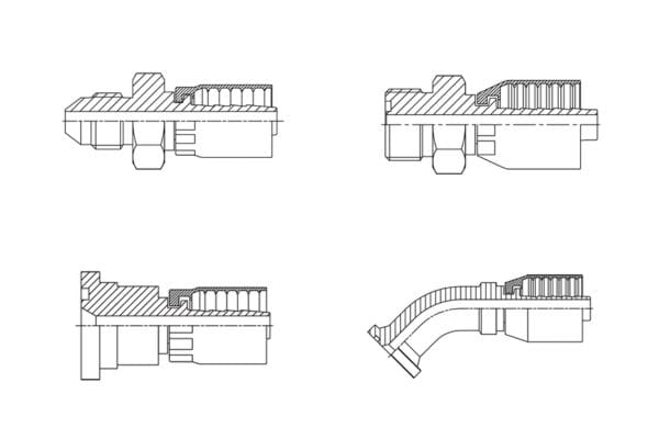
A one-piece hydraulic hose fitting has its body or stem and ferrule preassembled or retained together. That construction describes the hose attachment, while the equipment end can use different threads and sealing methods.
Two Interfaces Still Need Separate Checks
At the hose end, the stem enters the hose and the ferrule is crimped according to a specification validated for that combination. At the equipment end, the fitting connects to a port, adapter, or another component through its identified sealing arrangement. Supplying the stem and ferrule together can reduce separate ferrule selection, but it does not establish compatibility, correct crimping, or freedom from leakage.
A female swivel nut is not the ferrule, and tightening that nut does not adjust the crimp holding the hose. Likewise, “one-piece” does not mean every component is machined from one solid piece, nor does it make the product reusable or field-attachable. Keep the two interfaces separate when recording a fault: the location of the wet area matters more than the general description printed on the parts bin.
Identify Where the Connection Makes Its Seal
The threads you tighten do not always provide the fluid seal. Before selecting a repair, identify the connection standard and the surfaces or sealing elements that prevent fluid escape.
Compare the Sealing Mechanisms
In a conventional JIC 37-degree connection, matching metal cones provide the sealing interface while the threaded nut draws the components together. An ORFS connection uses an O-ring at the mating flat faces, typically retained in a groove on the male face. Neither arrangement is repaired by wrapping thread tape around its fastening threads, because the tape does not restore the sealing interface.
NPT tapered pipe threads require a different assessment because the mating thread geometry participates in the seal, with suitable sealing material applied as the product instructions require. Do not extend that instruction to every tapered-thread designation or assume that any available tape or compound is compatible with the fluid and application. The connection type determines the assembly method; the presence of visible threads does not.
| Connection or interface | Main sealing arrangement | What additional nut tightening cannot correct |
| Conventional JIC 37-degree connection | Matching metal sealing cones | Damaged cones, incorrect geometry, or unsuitable mating parts |
| ORFS connection | O-ring between mating flat faces | Missing, incorrect, cut, or displaced O-ring |
| NPT connection | Tapered thread engagement with specified sealing material | Incorrect threads, damaged components, or an unsuitable sealing product |
| Crimped hose attachment | Approved hose, stem, and ferrule assembled to validated requirements | Incorrect hose compatibility, preparation, insertion, or crimping |
Thread diameter and pitch are only part of fitting identification. Confirm male or female configuration, straight or tapered thread, connection standard, seat angle, sealing face, and any O-ring arrangement using appropriate dimensions and product information. JIC, SAE 45-degree flare, BSPP, BSPT, ORFS, ORB, metric, DIN, and JIS configurations must not be accepted as interchangeable from appearance or partial thread engagement.
Why More Tightening Can Leave the Leak Unresolved
More wrench resistance does not prove that the sealing interface is correctly assembled. Friction, misalignment, damaged threads, and mechanical loading can all interfere with the intended connection.
Separate Insufficient Tightening From a Component Problem
For an otherwise correct connection that has not reached its specified assembly condition, the approved tightening procedure remains relevant. Once a seal or mating surface is damaged, however, applying more force is not equivalent to replacing the damaged component or restoring the approved geometry. Excessive tightening can deform or damage connection features, but the specific failure mode depends on the design and should not be generalized to every fitting.
Alignment problems require a separate correction: the nut should not be used as a tool to drag an incorrectly positioned line into place. During assembly, distinguish the intended rotating nut from the components that require support, and follow the instructions for holding the connection without twisting the hose. Stop when engagement feels abnormal or parts cannot be aligned as required; apparent tightness reached through binding is not an acceptable assembly check.
A recurring leak also deserves review of the installation conditions rather than another automatic increase in torque. Examine routing, support, vibration exposure, temperature changes, and movement against the equipment and component requirements. Do not diagnose the cause from timing alone, but record whether leakage began immediately after replacement, after maintenance, or during operation so the inspection can address the actual circumstances.
Locate the Leak Before Disassembling the Assembly
Oil can move along a fitting, hose, or bracket before forming a visible drop. Confirm the origin through the approved inspection procedure instead of selecting the nearest accessible nut.

Establish a Safe Inspection Sequence
Stop and isolate the equipment, control supported loads, and release hydraulic pressure and stored energy according to the equipment manufacturer’s procedure before hands-on inspection or disassembly. A stopped pump or a single pressure-gauge reading does not replace the specified verification process. Never loosen a connection as an improvised pressure-release method or use your hand to search for pinhole leakage.
Once the equipment is in the required safe condition, clean the accessible area using approved materials and distinguish the equipment-end connection from the ferrule, hose, and nearby adapters. If locating the source requires an operating check, follow the approved diagnostic procedure with its safeguards; do not treat that as permission to touch, tighten, or disconnect a pressurized assembly. Where the source remains uncertain, obtain a qualified assessment rather than disassembling several serviceable joints by guesswork.
Use the inspection record to answer a short set of practical questions:
- Does the first identified leakage originate at the mating connection, an adjacent port, or the hose attachment?
- Is the joint newly assembled, previously disturbed, or already established in service?
- Are the connection type, part identification, and assembly instructions available?
- Can the assembly be aligned without forcing the hose or loading the joint?
- Does the required inspection reveal damage or an unresolved compatibility question?
Correct the Identified Fault at the Right Interface
A connection-end leak and a crimp-area leak require different technical checks. Correcting the wrong interface can create another fault while leaving the original problem untouched.
Check Sealing Parts and Hose Compatibility Separately
For a confirmed connection-end issue, inspect the mating surfaces, threads, and specified seal after safe disassembly. Check O-ring dimensions, material, condition, and seating where applicable, and follow the product requirements for replacement, lubrication, cleanliness, and reassembly. Use only an approved lubricant compatible with the seal and service conditions; an unidentified compound should not become a universal assembly aid.
If leakage originates at the hose attachment, do not attempt to correct it by tightening the equipment-end nut or adding an external clamp. Verify the hose manufacturer and series, construction, inside diameter or dash size, fitting stem design, and ferrule design against an approved combination. Then check the specified preparation, skive or no-skive requirement, insertion depth, crimper, dies, final crimp diameter, tolerance, and inspection method; there is no universal setting for all one-piece fittings.
A matching dash size cannot establish that a replacement stem and ferrule work with an unidentified hose. Likewise, measuring a used crimp does not establish a valid target for manufacturing another assembly, and re-crimping a leaking end is not an automatic repair route. Follow the manufacturer’s disposition for the affected assembly, including replacement when required, rather than improvising a temporary high-pressure connection with mismatched parts.
Reassemble to Product Instructions and Document the Result
The correct assembly standard comes from the identified product and application. Neither “another half turn” nor “as tight as possible” can replace it.
Confirm the Procedure and Service Conditions
Use the manufacturer’s specified torque, angle, flats, or other applicable assembly method, including its defined starting condition and any distinction between initial assembly and reassembly. Thread condition, material, finish, and lubrication can affect the instructions, so do not substitute a value taken from another size or connection. Where a special wrench attachment is used, follow the tool instructions for achieving the intended result rather than assuming every setup delivers the same fastener torque.
Before release, confirm that the approved assembly is suitable for working pressure, pressure impulse, temperature, hydraulic fluid, corrosion exposure, vibration, mechanical load, and routing. Its permissible pressure cannot exceed the limiting applicable component or assembly rating, including the connected port and adapters; the lowest rating does not validate an otherwise incompatible combination. Burst pressure is not allowable working pressure, and a successful brief leak check does not establish the long-term suitability of unapproved parts.
Keep the confirmation package focused on the information needed to reproduce the repair:
- Connection: standard, dimensions, sealing method, mating component, and installation orientation.
- Hose assembly: hose series and size, fitting series, assembly length, and validated crimp reference.
- Operating conditions: working pressure, temperature, fluid, movement, and relevant external exposure.
- Completion record: replaced components, assembly procedure, specified inspections, and release status.
Protect open lines and ports from contamination, then carry out installation and return-to-service checks according to the equipment requirements. Record the verified part numbers and assembly data rather than leaving “same as sample” as the only replacement description. If leakage remains, stop the uncontrolled adjustment cycle and reassess the source, component condition, and identification; do not release an unresolved repair simply because the visible leak has temporarily decreased.
Conclusion
One-piece hydraulic hose fittings simplify one aspect of component handling, but reliable sealing still depends on correct identification and assembly at both ends. When oil appears, establish the safe inspection condition and locate the source before deciding whether tightening is relevant. A damaged cone, unsuitable O-ring, misaligned line, or incorrect hose-and-fitting combination needs its own correction. Correct matching matters more than visual similarity or the lowest unit price. Prepare the fitting identification, sealing details, hose series, operating conditions, and applicable assembly instructions before ordering parts or reassembling the connection. Finish with the equipment’s prescribed inspections and a clear repair record, so the next maintenance task begins with verified information instead of another guess at wrench force.
Frequently Asked Questions
Does a swivel nut allow continuous hose rotation during operation?
Do not assume that it does. A connection swivel may assist assembly and orientation without being rated as a live rotary joint. Verify its intended function and address operational rotation through the approved connection and routing design.
Can a one-piece crimp fitting be removed and installed on a new hose?
Do not reuse a permanent crimp fitting unless its manufacturer explicitly permits the procedure. One-piece construction does not establish reusability. Field-attachable products have their own component, assembly, and reuse requirements.
Does replacing an O-ring with a harder material solve repeated leakage?
Not automatically. The required seal depends on the specified dimensions, material properties, fluid, temperature, and connection design. Changing hardness without checking those requirements can leave the actual fault unresolved.
Can an adapter make a different fitting acceptable for an urgent repair?
Only when the complete proposed arrangement is verified for the application. Confirm both connections, ratings, sealing methods, installation dimensions, and effects on routing and support. Availability alone is not evidence that the substituted arrangement is suitable.
Should every established connection be tightened during preventive maintenance?
No universal retightening rule applies to all hydraulic connections. Follow the equipment inspection and maintenance instructions, including any specified checks for the particular fitting. Unnecessary disturbance can create additional work and requires its own correct reassembly.