Hydraulic Coupler Types: Which One is Right for You?
Table of Contents
Introduction
Hydraulic couplers are essential components in hydraulic systems, serving as the connection points that allow for the seamless transfer of hydraulic fluid between different parts of the machinery. In hydraulic systems, these couplers play a vital role by ensuring that the fluid power is transmitted effectively, minimizing leaks, and maintaining system pressure. Choosing the right hydraulic coupler is of utmost importance, as the wrong selection can lead to inefficiencies, increased wear and tear, and even system failures. This article will provide a comprehensive overview of the various types of hydraulic couplers, their specific applications, and key considerations for selecting the most suitable coupler for your needs.
Understanding Hydraulic Couplers
Definition and Basic Function
Hydraulic couplers, also known as hydraulic quick couplings, are devices used to connect and disconnect hydraulic lines quickly and efficiently. Their basic function is to facilitate the smooth and swift connection of hydraulic hoses, pipes, or tubes without the need for tools, which is particularly beneficial in applications requiring frequent assembly and disassembly. Hydraulic couplers are designed to handle high-pressure fluid transfer, ensuring a secure and leak-free connection that maintains the integrity and performance of the hydraulic system. By enabling rapid connections, these couplers help minimize downtime during maintenance or equipment changes, enhancing overall operational efficiency.
Key Components of Hydraulic Couplers
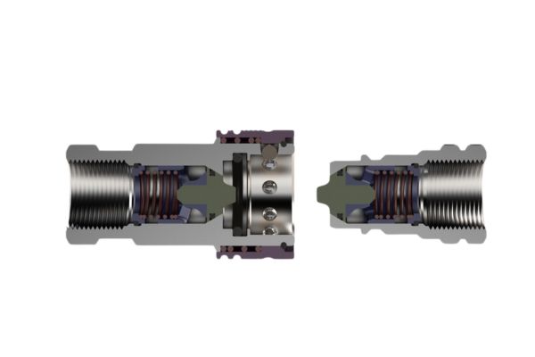
Hydraulic couplers are composed of several key components that work together to provide a secure and reliable connection. These components typically include:
Body: The main structure that houses the internal components and provides the connection interface.
Valve Mechanism: Often includes a poppet or ball valve that controls the flow of hydraulic fluid and prevents leaks when the coupler is disconnected.
Locking Mechanism: Ensures that the coupler remains securely connected under pressure. This can include various locking systems such as ball locking or thread locking.
Seals: Usually made of high-quality materials like rubber or synthetic compounds to prevent fluid leakage and ensure a tight seal.
Sleeve: The outer part that users manipulate to connect or disconnect the coupler. It often incorporates a push-pull mechanism for ease of use.
Each of these components plays a crucial role in the functionality and reliability of the hydraulic coupler, ensuring it can withstand the rigors of high-pressure applications while providing a safe and efficient connection.
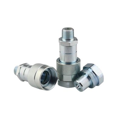
Quick-release couplers are engineered for fast and effortless connection and disconnection of hydraulic lines without the necessity for tools. This feature is particularly valuable in environments where rapid setup and breakdown are frequent, thereby enhancing operational efficiency. These couplers typically comprise two primary components: a male and a female part, which engage with a straightforward push-pull action. The design commonly incorporates a locking mechanism, such as ball bearings or a sliding sleeve, to ensure a secure and reliable connection under pressure. This mechanism helps prevent accidental disconnections and ensures that the coupler maintains a tight seal even in demanding conditions.
Flat-Face Couplers
Flat-face couplers are specifically designed to minimize fluid loss and prevent contamination during connection and disconnection. They feature flat mating surfaces that seal directly against each other, eliminating cavities where hydraulic fluid can be trapped. This design also reduces air inclusion and spillage, making them ideal for maintaining the cleanliness of hydraulic systems. The flat-face design ensures that dirt and debris are less likely to enter the hydraulic system during connection and disconnection, thereby enhancing the overall reliability and longevity of the equipment.
ISO-A Couplers
ISO-A couplers are standardized quick couplers that conform to the ISO 7241-1 Series A standard. They feature a poppet valve design that ensures reliable sealing and a robust connection. The standardized design means these couplers are interchangeable with other ISO-A couplers from different manufacturers, providing versatility and ease of use in various applications. The poppet valve mechanism helps maintain a secure seal and prevents fluid leakage, making them suitable for a wide range of hydraulic applications.
ISO-B Couplers
ISO-B couplers conform to the ISO 7241-1 Series B standard and feature a ball-locking mechanism. This design ensures secure connections and disconnections, making them suitable for a variety of hydraulic applications. The ball-locking mechanism provides a reliable and strong connection, which is crucial for maintaining the integrity and performance of the hydraulic system.
Screw-To-Connect Couplers
Screw-to-connect couplers, as the name suggests, utilize a threaded connection that ensures a secure and leak-free joint, even under high-pressure conditions. These couplers consist of a male and a female component, which are screwed together to form an airtight seal. The design is highly robust, typically made from high-strength materials to withstand the mechanical stresses and vibrations encountered in demanding environments. The threaded interface provides an exceptionally strong connection that is less likely to disconnect accidentally, making it ideal for critical applications where reliability is paramount.
High-Pressure Couplers
High-pressure couplers are engineered to handle extremely high hydraulic pressures, often exceeding those managed by standard couplers. They typically feature reinforced construction, utilizing high-strength materials such as hardened steel or advanced alloys. These couplers incorporate sophisticated sealing mechanisms, such as multiple O-rings or advanced valve designs, to ensure safe and reliable performance under extreme pressure conditions. The design also includes safety features to prevent accidental disconnection and to handle the intense forces encountered in high-pressure environments.
Threaded Couplers
Threaded couplers feature a threaded interface that provides a secure and leak-free connection, ideal for applications where a strong and reliable connection is essential. These couplers consist of a male and female component, each with threaded ends that screw together to form a tight, durable seal. The threaded design ensures that the connection can withstand varying pressures and mechanical stresses, making it suitable for a wide range of demanding applications. Threaded couplers are typically constructed from durable materials such as steel or brass, which provide longevity and reliability.
Start with the manufacturer, series, and part number if available. If markings are missing, compare the nipple profile and key dimensions with a reliable identification drawing. Photos should show the mating face, side profile, locking groove, and port connection.
Do not use the hose thread size as a substitute for identifying the coupling interface. If the existing half cannot be positively identified, further dimensional review or selection of a complete approved pair may be needed.
Check Working Pressure and Duty
Use the coupling’s published working-pressure rating for the selected size, material, and operating conditions. Burst pressure is a test characteristic, not a working-pressure limit.
Pressure spikes and repeated cycles also matter. Describe the machine duty and any known surge conditions so the coupling can be reviewed for the actual application. Where connected and disconnected ratings differ, apply the appropriate limit to each condition.
Select Body Size by Flow and Pressure Drop
Use the expected flow rate and the manufacturer’s pressure-drop curve to select the coupling body size. A port that fits the hose does not necessarily provide the required flow performance.
Check the stated test conditions when comparing curves, including fluid viscosity and whether the data represents a connected pair. For circuits with changing flow, review the operating range rather than only a single nominal value.
Confirm Connection Conditions
Determine whether pressure may remain in the machine, attachment, or both after shutdown. Trapped fluid can make connection difficult, so the required connection capability should be part of the original specification.
Working-pressure rating and connect-under-pressure rating are separate. A coupling approved to carry pressure while connected may still require depressurization before connection or disconnection. Follow the equipment and coupling instructions; do not force a connection or loosen a fitting to release trapped pressure.
Match Materials, Seals, and Environment
Identify the hydraulic fluid and its temperature range, then check compatibility with the coupling body, seals, and any internal components. External conditions also matter, including moisture, road salt, cleaning chemicals, and dirt.
Select protective caps or plugs suitable for the coupling and keep disconnected faces clean. Corrosion resistance alone does not confirm fluid compatibility or the required pressure performance.
Verify the Complete Mating Pair
Confirm both halves by series, interface size, and manufacturer documentation. Standardized interface dimensions can support interchange, but they do not automatically establish identical pressure ratings, seal materials, flow performance, or connection capability.
For mixed-brand pairs, confirm the manufacturers’ interchange guidance and any applicable performance limits. Keep the approved male and female part numbers together in the equipment or purchasing record.
Conclusion
Throughout this article, we have explored the various types of hydraulic couplers. Choosing the right hydraulic coupler is essential for maintaining the efficiency, reliability, and safety of your hydraulic system. Understanding the strengths and limitations of each type of coupler will help you make an informed decision that can enhance the performance of your equipment and reduce downtime.
A hydraulic coupler is a device used to connect and disconnect hydraulic lines quickly and securely, allowing for the transfer of hydraulic fluid between components in a hydraulic system.
Consider factors such as pressure rating, temperature range, fluid compatibility, environmental conditions, ease of use, and maintenance requirements. Match these factors to your specific application needs.
The main types of hydraulic couplers include quick-release couplers, flat-face couplers, ISO-A couplers, ISO-B couplers, screw-to-connect couplers, high-pressure couplers, and threaded couplers.
Many hydraulic couplers conform to industry standards such as ISO or SAE, making them interchangeable between brands. However, always verify compatibility to ensure a secure and leak-free connection.
Regular maintenance, including inspections for wear and tear, is crucial. Replace hydraulic couplers based on the manufacturer’s recommendations or if you notice signs of damage, leaks, or reduced performance.
Quick-release couplers allow for fast and easy connection and disconnection without tools, minimizing downtime during maintenance or equipment changes and reducing the risk of fluid leaks during disconnection.