
55° vs. 60° thread angles · 1:16 taper · R, Rc, Rp, and G designations · Nominal pipe sizes · Thread matching and sealing practices
A pipe fitting can feel tight and still leak. In some cases, the sealing material is unsuitable or a sealing surface is damaged. In others, the problem begins earlier: two components with different thread standards have been assembled because they look similar or appear to screw together.
NPT, PT, and G threads are among the most frequently encountered pipe-thread designations in pneumatic equipment, pressure regulators, gauges, valves, and industrial piping. Understanding their differences helps explain why a connection resists tightening, why a seal fails, and what information should be confirmed before ordering another fitting.
Tight Does Not Mean Leak-Free: Why Pipe Threads Cause Problems
Similar-looking connections can hide different standards
When a pneumatic system loses pressure during a holding test, threaded connections are one of the areas worth investigating. However, pressure loss alone does not identify the leak location. Valves, tubing, seals, and other components must also be considered.
At a threaded joint, the difficulty is often that different standards look close enough to encourage a trial assembly. A tapered fitting may begin to enter a parallel port. Two threads may share the same nominal size or even the same number of threads per inch. Resistance then develops, and the installer assumes the connection only needs more force.
That resistance may come from a mismatch rather than correct engagement. Continuing to tighten can deform the threads or damage the female component.
Three common misunderstandings
The first misunderstanding is treating an R tapered male thread and a G parallel female thread as a standard R × Rp connection. Although both G and Rp female threads are parallel, they belong to different standard arrangements and should not be substituted without a verified basis.
The second is assembling NPT with a 55-degree pipe thread. NPT has a 60-degree thread angle, while the relevant British-derived pipe-thread systems use 55 degrees. Similar appearance does not establish compatibility.
The third is assuming identical size labels mean identical dimensions. A G1/4 pipe thread and a 1/4-20 unified screw thread are entirely different sizes and thread systems. They should never be compared simply because both include “1/4.”
The Pipe-Thread Family: British-Derived and American Systems
The 55-degree Whitworth-derived family
The Whitworth thread form uses a 55-degree included angle and a rounded basic profile. Pipe-thread systems developed from this family include both thread-sealing and non-thread-sealing arrangements.
For thread-sealing connections, ISO 7-1 uses the designations R, Rc, and Rp. These identify a tapered external thread, a tapered internal thread, and a parallel internal thread respectively.
For connections where pressure tightness is not made on the threads, ISO 228-1 uses the designation G. These threads are parallel, and the complete connection relies on another specified sealing feature.
Older documents and commercial descriptions may use PT, PF, PS, or ZG. Such markings need to be interpreted against the original standard and drawing rather than translated automatically into a modern designation.
The 60-degree American family
NPT belongs to the American pipe-thread system and uses a 60-degree included thread angle. ASME B1.20.1 covers general-purpose inch pipe threads, including NPT and several related forms.
NPTF is a dryseal pipe-thread system covered separately by ASME B1.20.3. Its controlled crest and root geometry is intended to close the spiral leakage path more completely than ordinary NPT.
These systems should also be distinguished from ordinary metric and unified screw threads. Metric M threads and unified UN threads commonly use a 60-degree angle, but sharing an angle does not make them NPT.
Chinese standards associated with these systems
The original article references the following Chinese standards:
| Thread System | Referenced Chinese Standard | Related International or American System |
| 60° thread-sealing pipe threads | GB/T 12716-2011 | NPT-related dimensions and requirements |
| 55° thread-sealing pipe threads | GB/T 7306.1-2000 and GB/T 7306.2-2000 | ISO 7-1 |
| 55° non-thread-sealing pipe threads | GB/T 7307-2001 | ISO 228-1 |
These references help explain the standard families. Before using them in a purchase specification, inspection procedure, or design document, confirm the applicable edition and its current status. Standards from related systems should not be declared fully interchangeable without reviewing the relevant requirements.
NPT: The American 60-Degree Tapered Pipe Thread
Thread angle and taper
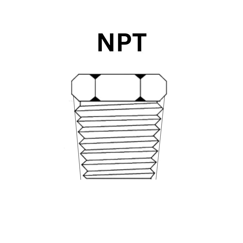
NPT is commonly described as National Pipe Taper thread. It has a 60-degree included thread angle and a diameter taper of 1:16.
A 1:16 diameter taper means that the diameter changes by one unit over an axial distance of sixteen units. The corresponding angle between the tapered surface and the axis is approximately 1 degree 47 minutes.
This is the half-angle of the taper. It should not be confused with the 60-degree thread angle, which describes the angle between the thread flanks.
The basic NPT profile has controlled crest and root truncation. For identification and inspection, the actual profile limits should be taken from the applicable standard rather than judged from a simplified illustration.
How NPT forms a pressure seal
As a male NPT fitting enters a female NPT component, the taper produces progressively tighter engagement. In a conventional NPT connection, an appropriate thread sealant is normally used to address potential leakage paths through the threaded joint.
The sealant must suit the medium, pressure, temperature, materials, and cleanliness requirements. PTFE tape and liquid thread sealants are possible options, but neither is suitable for every application.
Installation requirements are also product-specific. There is no universal tightening torque or number of turns that can be safely applied to every NPT fitting.

NPTF: the dryseal variation
NPTF controls the thread crest and root relationship to reduce the spiral leakage path through metal contact.
However, “dryseal” should not be interpreted as a universal instruction to assemble every NPTF connection without sealant or lubricant. Follow the component manufacturer’s requirements and the application specification.
Likewise, a fitting specified as NPTF should not be replaced with NPT merely because the parts appear similar. The drawing requirement, inspection method, and intended mating connection must be preserved.
R and PT: The 55-Degree Thread-Sealing System
What the letters mean
The ISO 7-1 designations describe different thread forms:
| Designation | Meaning | Intended Role |
| R | Tapered external thread | Male thread used in a specified thread-sealing connection |
| Rc | Tapered internal thread | Female thread intended to mate with R |
| Rp | Parallel internal thread | Female thread intended to mate with R |
| PT | Older JIS designation associated with tapered pipe threads | Requires confirmation against the applicable document |
| ZG | Historical Chinese designation associated with tapered pipe threads | Requires interpretation against the original standard |
PT and ZG remain familiar workshop terms, but they should not replace a complete technical specification.
When reviewing an older drawing, establish whether the required component is male or female, whether the female thread is tapered or parallel, and which standard governs the connection.
Two recognized combinations
The two important combinations are:
R male × Rc female: a tapered external thread assembled with a tapered internal thread.
R male × Rp female: a tapered external thread assembled with a parallel internal thread.
Both are recognized arrangements within the thread-sealing system. This is why a blanket statement that “tapered and parallel threads must never be connected” is incorrect.
The correct distinction is between a specified tapered-to-parallel combination and an unverified mixture of different thread systems.
Why Rp must not be confused with G
Rp and G internal threads are both parallel, but they have different standard purposes and requirements.
An unidentified straight female thread cannot be classified as G solely because it has no visible taper. Equally, a G female port should not automatically be treated as an Rp port because an R male fitting can begin to enter it.
Check the drawing, product information, or appropriate inspection results. Trial assembly is not a substitute for confirming the thread.
G: The 55-Degree Parallel Pipe Thread
“Non-thread-sealing” does not mean the connection cannot seal
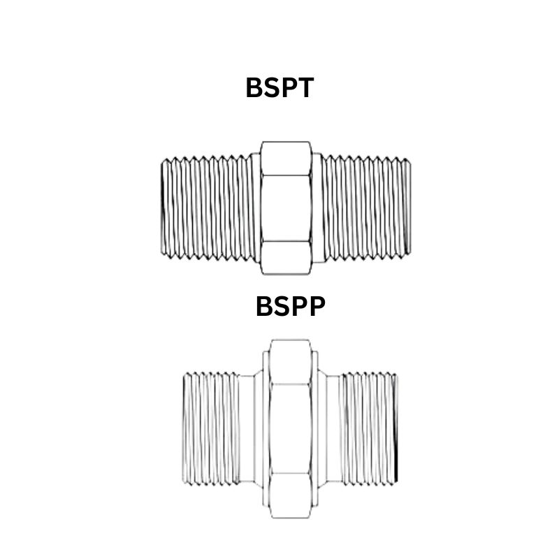
G identifies parallel pipe threads under ISO 228-1. The term “non-thread-sealing” means pressure tightness is not established by the thread flanks themselves.
The threads provide mechanical engagement and clamping. A separate feature creates the seal.
Depending on the complete connection design, that feature may be a gasket, bonded washer, O-ring, or matching cone surface. Therefore, it is too restrictive to say every G connection seals with a flat end-face washer.
The complete interface determines the sealing method.
Why the sealing surface matters
Imagine two components with the same G thread size. One is designed to seal beneath a shoulder, while the other expects a matching internal cone.
The threads may engage, but that does not establish the required sealing contact. The same problem occurs if a specified O-ring is missing or the port face is damaged.
Before assembling a G connection, locate the intended seal and inspect its mating surface. Extra thread tape cannot replace the missing geometry or restore a damaged sealing face.
Where G connections are used
G connections appear in instrumentation, pneumatic equipment, hydraulic products, valves, and other industrial systems.
They should not be described as inherently limited to low pressure. The permissible operating conditions depend on the complete product design, material, size, seal, and manufacturer’s rating.
Their suitability for repeated maintenance also depends on the product and condition of its components. Separate seals can often be serviced, but threads and sealing surfaces still require inspection.
NPT, R/Rc/Rp, and G Compared
Geometry and sealing method
| Feature | NPT | R / Rc / Rp | G |
| Included thread angle | 60° | 55° | 55° |
| External thread form | Tapered | R is tapered | Parallel |
| Internal thread form | Tapered for NPT | Rc is tapered; Rp is parallel | Parallel |
| Diameter taper | 1:16 | 1:16 for R and Rc; none for Rp | None |
| Basic sealing approach | Thread sealing, normally with suitable sealant | Specified thread-sealing pair, normally with suitable sealant | Separate sealing feature |
| Main reference | ASME B1.20.1 | ISO 7-1 | ISO 228-1 |
| Key identification concern | Can resemble other tapered pipe threads | Rp and Rc must be distinguished | Complete seal geometry must be identified |
The table should be read by individual thread form. Describing the entire R/Rc/Rp group simply as “tapered” would incorrectly include Rp.
Why thread angle alone is insufficient
A 60-degree tapered thread may suggest NPT, but suggestion is not confirmation. Other thread systems and product-specific forms exist, and small or damaged threads are difficult to assess visually.
Likewise, distinguishing a rounded profile from a truncated profile can be difficult without suitable equipment.
Use taper, diameter, pitch, documentation, and connection geometry together. If identification remains uncertain, obtain a more reliable inspection rather than forcing assembly.
Matching Rules and Sealing Practice
Which combinations are recognized?
| Combination | General Guidance |
| R male × Rc female | Recognized thread-sealing combination |
| R male × Rp female | Recognized thread-sealing combination |
| NPT male × NPT female | Corresponding thread combination; follow specified sealing instructions |
| G male × G female | Confirm the complete matching sealing arrangement |
| R male × G female | Do not assume equivalence to R × Rp; require explicit product approval |
| NPT × 55° pipe-thread systems | Do not directly mix |
| NPTF connections | Confirm the specified mating arrangement and assembly requirements |
Even a recognized combination requires the correct size, acceptable condition, suitable materials, and proper installation.
If two components use different standards, select a suitable conversion adapter with a verified connection at each end.
Applying PTFE tape
Where PTFE tape is permitted, apply it to the male tapered thread according to the tape and fitting instructions.
For a conventional right-hand thread, wrap in the direction that prevents the tape from unwinding during assembly. Keep the leading end clear as instructed to reduce the chance of loose material entering the system.
Do not prescribe one number of wraps for every fitting. Tape thickness, thread size, product design, and service conditions vary.
Tape is also not a universal treatment for G connections, cone seats, flare connections, or tube fittings. Apply sealing material only where the connection design calls for it.
Oxygen and other oxidizing services
Oxygen systems require appropriate cleanliness and oxygen-compatible materials. A sealant or lubricant should be selected for the specified oxygen pressure, temperature, and application.
“PTFE” or “oil-free” on its own is not a complete approval basis. Check the product documentation and system requirements.
Cleaning procedures, handling methods, tools, and contamination control must also follow the applicable oxygen-service requirements.
Stainless steel galling
Stainless steel threaded components can gall during assembly. Adhesive damage between contacting surfaces may cause the connection to seize before the intended assembly position is reached.
Follow the manufacturer’s requirements for assembly speed, lubrication, and tightening. Where a lubricant or anti-seize product is allowed, it must also be compatible with the medium and cleanliness requirements.
A seized fitting should not simply be subjected to increasing force. Inspect the components and determine whether replacement is necessary.
Specialty gas and high-purity systems
High-purity systems often use welded, face-seal, or other specified connections to control leakage and contamination.
The important distinction is between a thread-sealing pipe joint and a connection where threads only apply force to a separate seal. A face-seal fitting can contain threaded components without sealing through those threads.
Therefore, “high-purity systems contain no threads” is too broad. Connection selection depends on gas properties, purity requirements, leak criteria, materials, cleaning, and the governing design specification.
Cylinder-valve connections also require separate identification. DISS, CGA, and other systems are not interchangeable labels, and the correct connection depends on the cylinder and service.
Seven Rules for Selecting Pipe Threads Correctly
1. Identify the standard before selecting the size
A size description such as “1/4 inch” is incomplete. Confirm NPT, R, Rc, Rp, G, or the relevant alternative.
2. Separate tapered and parallel forms accurately
R and Rc are tapered; Rp and G are parallel. Do not describe every 55-degree thread-sealing connection as tapered on both sides.
3. Find the actual sealing location
Determine whether the seal forms at the threads, a washer, an O-ring, a cone, or another specified surface.
4. Treat nominal dimensions correctly
A pipe-thread fraction is not its measured outside diameter. Use the appropriate table and measurement position.
5. Combine identification methods
Use markings, documents, taper, diameter, pitch, and sealing geometry. A few turns of engagement do not prove compatibility.
6. Investigate leakage before applying more force
Check the actual leak location, thread pairing, seal condition, sealing surfaces, and external pipe loads. Isolate and depressurize the system before dismantling.
7. Record the complete connection for future orders
Keep the approved thread details, mating-port information, seal requirements, material, and drawing revision. For multi-SKU orders, identify each end of every fitting separately.
A useful selection record makes the next order easier to verify and reduces the chance of repeating an incorrect connection.
For distributor replenishment, OEM production, or recurring pipe-fitting orders, provide Topa with your drawings or part-number list, both-end connection details, sealing requirements, operating conditions, and quantities by SKU. This gives the specification review a clear technical starting point.
Technical references: ASME B1.20.1, Swagelok Thread and End Connection Identification Guide, and NPT dimensional reference. Thread identification and dimensional distinctions above were checked against manufacturer and standards information; product-specific assembly and service limits still require the applicable documentation.