In manufacturing environments, even minor inefficiencies in fluid transport systems can compound over time, resulting in significant energy waste. For instance, a poorly designed compressed air system with suboptimal pipe sizing can increase energy consumption by up to 30%, directly impacting operational costs and environmental footprint. Similarly, in hydraulic systems, improper pipe installation can lead to pressure losses that diminish machine performance and responsiveness.
Pipe Diameter and Length Optimization
The selection of appropriate pipe diameters and the optimization of pipe lengths represent foundational decisions in any hard pipe installation project. These seemingly simple parameters have profound implications for system performance, energy consumption, and operational costs over the entire lifecycle of the installation.
Scientific Selection of Pipe Diameters Based on Flow Characteristics
Pipe diameter selection must be approached as a scientific calculation rather than an intuitive guess. The relationship between pipe diameter and fluid flow follows complex fluid dynamic principles governed by the Reynolds number, which characterizes whether flow will be laminar or turbulent. For most industrial applications, the goal is to maintain flow velocities within specific ranges that balance efficiency and practicality.
For hydraulic systems, recommended flow velocities typically range from 3-5 m/s for pressure lines and 1-2 m/s for return lines. Exceeding these parameters introduces excessive friction losses that manifest as heat generation and pressure drops. In compressed air systems, maintaining velocities below 6 m/s in main distribution lines and 15 m/s in branch lines prevents excessive pressure losses while ensuring economical pipe sizing.
The Darcy-Weisbach equation provides a mathematical framework for calculating pressure loss due to friction:
Δp = λ × (L/D) × (ρ × v²/2)
Where:
- Δp represents pressure loss
- λ is the friction factor
- L is pipe length
- D is pipe diameter
- ρ is fluid density
- v is flow velocity
This equation clearly demonstrates how undersized pipes (small D) dramatically increase pressure losses, requiring more energy input to maintain desired flow rates.
The Relationship Between Pipe Length and System Efficiency
While pipe length is often dictated by the physical layout of equipment, optimizing routing to minimize unnecessary runs yields substantial efficiency benefits. Each meter of additional piping introduces friction losses that accumulate throughout the system. The principle of “shortest path possible” should guide installation planning, with careful consideration of both horizontal and vertical routing.
In practical terms, a 10% reduction in total pipe length can yield approximately 10% reduction in friction-related pressure losses, translating directly to energy savings. However, the shortest geometric path is not always optimal when considering maintenance access requirements, thermal expansion accommodation, and vibration isolation needs.
When analyzing system layouts, engineers should employ the concept of “equivalent pipe length” to account for the additional resistance introduced by fittings, valves, and bends. For instance, a standard 90° elbow can introduce resistance equivalent to 30-60 pipe diameters of straight pipe, highlighting why seemingly minor routing decisions have significant performance implications.
Calculating Optimal Flow Rates to Minimize Energy Loss
The relationship between flow rate, pipe diameter, and energy consumption follows a cubic function—doubling the flow rate through the same diameter pipe increases pressure drop and pumping power requirements by approximately eight times. This non-linear relationship makes proper sizing critical for energy-efficient operation.
For systems with variable flow requirements, engineers must consider both peak demand and typical operating conditions. Sizing pipes solely for maximum flow scenarios often results in oversized systems that operate inefficiently during normal conditions. Conversely, undersizing to save on initial material costs invariably leads to excessive operational expenses through increased pumping energy requirements.
Flexible Connection Design Principles
In the realm of hard pipe installation, the implementation of flexible connection designs stands as a critical yet frequently overlooked aspect. These design elements accommodate the inevitable physical forces that act upon piping systems during operation, preventing premature failures and extending system longevity.
Understanding Thermal Expansion and Contraction Forces
All materials expand when heated and contract when cooled—a fundamental physical property that creates significant challenges in piping systems. In industrial environments where temperature fluctuations are common, rigid pipe installations experience tremendous stress as thermal expansion creates forces that can exceed several tons per square inch. These forces must be accommodated through deliberate design rather than resisted through rigid mounting.
The coefficient of thermal expansion varies by material: steel expands approximately 11.7 × 10^-6 per °C, stainless steel at 17.3 × 10^-6 per °C, and aluminum at 23.1 × 10^-6 per °C. For perspective, a 10-meter steel pipe experiencing a 50°C temperature increase will expand by approximately 5.85mm—a seemingly small value that generates enormous force if constrained.
Without proper accommodation, these forces concentrate at the weakest points in the system, typically at connections, bends, or material transitions. Over time, this stress cycling leads to fatigue failure, leaks, and catastrophic system breakdowns that interrupt operations and create safety hazards.
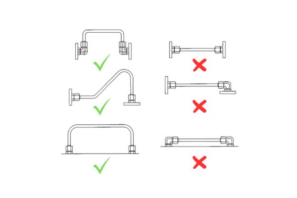
Implementation of Slack Bend Structures
The incorporation of slack bend structures represents one of the most effective methods for accommodating thermal movement in piping systems. These intentional bends, sometimes called expansion loops or offsets, provide the necessary flexibility to absorb movement without creating excessive stress on components.
When designing slack bends, several key parameters must be considered:
- The anticipated thermal movement based on temperature range and pipe material
- The available space for implementing the bend structure
- The pressure rating of the system, which influences the acceptable bend radius
- The structural support requirements to prevent unintended movement
The optimal slack bend design balances flexibility with space efficiency. For systems with severe space constraints, specialized expansion joints or bellows may substitute for geometric bends, though these components typically introduce additional maintenance requirements and potential failure points.
Beyond thermal considerations, slack bends also facilitate easier assembly and disassembly during maintenance operations. By incorporating strategic flexibility into the design, technicians can disconnect sections without requiring extensive disassembly of adjacent components, significantly reducing maintenance downtime and associated costs.
Pipe Bending Standards and Best Practices
The art and science of pipe bending represents a critical aspect of hard pipe installation that directly impacts system performance, fluid flow efficiency, and long-term reliability. Proper bending techniques prevent flow restrictions, minimize pressure drops, and ensure structural integrity throughout the system’s operational life.
Minimum Radius Requirements for Different Materials
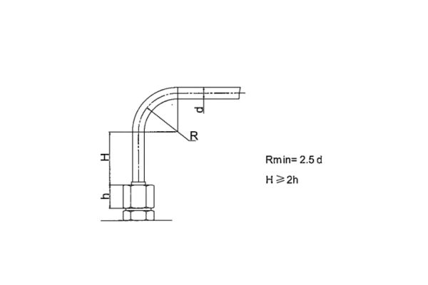
The minimum bending radius for hard pipes is not arbitrary but rather a carefully calculated parameter based on material properties and pipe dimensions. The industry standard minimum bending radius should be no less than 2.5 times the outer diameter of the pipe. This requirement exists to prevent material deformation that compromises structural integrity and creates flow restrictions.
Different materials exhibit varying degrees of ductility and therefore have specific bending limitations:
For carbon steel pipes, the minimum bending radius typically ranges from 2.5 to 3 times the outer diameter, depending on wall thickness and grade. Exceeding these limits results in thinning of the pipe wall on the outside radius and wrinkling on the inside radius, both of which compromise pressure ratings and create stress concentration points.
Stainless steel pipes, while generally more ductile than carbon steel, still require careful bending practices. The minimum radius for austenitic stainless steels (300 series) is approximately 2.5 times the outer diameter, while duplex stainless steels may require up to 3.5 times the outer diameter due to their higher strength and lower ductility.
Copper and copper alloy pipes allow tighter bends, with minimum radii as low as 2 times the outer diameter for annealed copper. However, work hardening during the bending process must be considered, as it can lead to cracking if multiple bends are made in close proximity.
Aluminum pipes typically require larger bending radii of 3 to 4 times the outer diameter due to their tendency to crack or wrinkle during forming operations. Special attention must be paid to heat-treated aluminum alloys, as bending can alter their mechanical properties.
Straight Section Requirements at Pipe Ends
A frequently overlooked aspect of pipe bending is the necessity of maintaining straight sections at pipe ends, particularly where connections will be made. As specified in the original document, the straight section length should be no less than twice the height of the pipe fitting nut. This requirement serves several critical functions in the overall system integrity.
First, straight end sections ensure proper seating of fittings and connections. When a fitting is installed on a curved section of pipe, the uneven stress distribution can prevent proper sealing, leading to leaks even when proper torque is applied. Additionally, the thread engagement may be compromised, reducing the pressure rating of the connection.
Second, straight sections facilitate proper alignment during installation. Pipes that are bent too close to the connection point create assembly challenges and often result in misaligned connections that introduce additional stress into the system. This misalignment accelerates wear on seals and can lead to premature failure.
Third, straight sections provide a stable area for pipe clamps and supports, which are essential for vibration control and load distribution. Without adequate straight sections, supports may be placed on curved portions of the pipe, creating point loads that can deform the pipe over time.
For high-pressure applications, the straight section requirements may increase to three or four times the fitting height to ensure adequate pressure containment and connection integrity. Similarly, for systems subject to thermal cycling or vibration, extended straight sections provide additional stability and stress distribution.
Vibration Suppression Solutions
Vibration in hard pipe systems represents one of the most insidious threats to system integrity and operational efficiency. Left unaddressed, vibration can accelerate component wear, create noise pollution, compromise connection integrity, and ultimately lead to catastrophic failures. Implementing effective vibration suppression solutions is therefore essential for any professional pipe installation.
Identifying Vibration Sources and Propagation Paths
Before implementing suppression measures, engineers must first understand the sources and transmission mechanisms of vibration within piping systems. Vibration typically originates from several common sources:
Reciprocating equipment, such as compressors and pumps, generates pulsations that travel through connected piping. These mechanical vibrations occur at frequencies related to the equipment’s operating speed and can be particularly damaging when they coincide with the natural frequency of the piping system, creating resonance conditions that amplify vibration amplitude.
Fluid-induced vibration occurs when turbulent flow creates pressure fluctuations within the pipe. This phenomenon is particularly prevalent in areas of flow disturbance such as valves, elbows, and diameter transitions. The resulting vibration energy can travel significant distances through the piping network, affecting components far from the original source.
External vibration from nearby machinery or processes can transfer into piping systems through shared mounting points or structural connections. Even seemingly minor external vibrations can become problematic when they excite resonant frequencies within the piping system.
Thermal cycling creates a form of low-frequency vibration as pipes expand and contract with temperature changes. While not typically considered vibration in the traditional sense, this movement creates similar wear patterns and stress concentrations if not properly accommodated.
Vibration propagation follows complex paths through both the fluid medium and the physical pipe structure. Structural-borne vibration travels through the pipe material and supporting structures, while fluid-borne vibration travels through the contained medium. Effective suppression strategies must address both transmission mechanisms.
Strategic Placement of Pipe Clamps and Supports
The strategic placement of pipe clamps and supports represents the foundation of effective vibration control. These elements serve dual purposes: they prevent excessive pipe movement while simultaneously isolating the pipe from external vibration sources.
The spacing of supports follows scientific principles rather than arbitrary guidelines. For horizontal runs, maximum support spacing can be calculated based on pipe diameter, material, and fluid weight to prevent sagging and associated stress concentrations. As a general rule, support spacing should not exceed 10-12 feet for 2-inch steel pipe, with proportionally closer spacing for larger diameters due to increased weight.
Critical locations requiring dedicated support include:
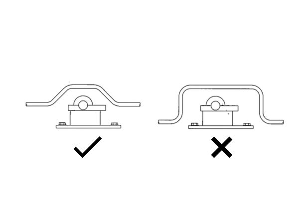
- Both ends of straight sections adjacent to bends, where vibration tends to concentrate due to directional changes in fluid flow
- Connection points between hard pipes and flexible hoses, which represent transition points with different vibration characteristics
- Near heavy components such as valves or instrumentation, which create localized mass concentrations
- At branch connections, where flow disturbances create turbulence and associated vibration
The type of support is equally important as its location. Rigid clamps should be used sparingly and primarily at fixed points where absolute position must be maintained. For most applications, vibration-isolating clamps incorporating elastomeric or composite materials provide superior performance by preventing the transmission of vibration between the pipe and supporting structure.
For systems operating at elevated temperatures, supports must accommodate thermal expansion while still providing vibration control. Sliding supports with low-friction interfaces allow necessary movement while maintaining position control. Spring hangers provide another solution for thermal movement accommodation while still restricting undesirable vibration.
Flow Resistance Optimization Design
The optimization of flow resistance within hard pipe systems represents a critical yet frequently overlooked aspect of installation design. Every bend, junction, and transition in a piping system introduces resistance that must be overcome through increased pumping power, directly impacting operational costs and system efficiency.
The Hidden Cost of 90° Bends in Piping Systems
Traditional 90° bends represent one of the most significant sources of flow resistance in piping systems. These sharp directional changes force fluid to rapidly alter course, creating turbulence, separation zones, and significant pressure drops. The physics behind this phenomenon relates to the conservation of momentum—fluid particles traveling in one direction resist changing direction, and overcoming this resistance requires energy.
The pressure loss coefficient (K-factor) for a standard 90° elbow typically ranges from 0.75 to 1.5, depending on the specific geometry and surface roughness. This means that a single 90° bend can introduce resistance equivalent to 30-60 pipe diameters of straight pipe. In systems with multiple bends, these losses compound dramatically, often accounting for 40-60% of the total system pressure drop.
Beyond energy considerations, sharp bends create secondary flow patterns that accelerate erosion, particularly in systems carrying particulate matter or in two-phase flow conditions. This erosion concentrates at the outer radius of the bend, gradually thinning the pipe wall and creating potential failure points. In corrosive environments, these turbulent zones also experience accelerated chemical attack due to enhanced mass transfer at the pipe wall.
The financial implications of excessive 90° bends become apparent when considering that each 1 psi (0.07 bar) of unnecessary pressure drop in a typical industrial compressed air system costs approximately $1,500-2,500 annually in additional energy consumption per 100 CFM of flow. For hydraulic systems, where pressures are significantly higher, the energy penalties become even more substantial.
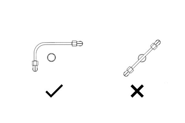
Implementing Dual 45° Bend Combinations
The strategic replacement of 90° bends with dual 45° bend combinations, represents one of the most cost-effective methods for reducing flow resistance. This configuration allows fluid to change direction more gradually, reducing turbulence and associated pressure losses. The pressure loss coefficient for this arrangement typically ranges from 0.4 to 0.6—approximately 40-60% lower than a standard 90° elbow.
When implementing dual 45° bend combinations, several design considerations maximize their effectiveness:
- The straight section between bends should be at least 2-3 pipe diameters in length to allow flow stabilization between directional changes.
- Consistent bend radius should be maintained throughout the system to ensure predictable flow characteristics.
- Proper alignment of the bends is critical—misalignment can create additional turbulence that negates the benefits of the dual-bend configuration.
- Support structures must accommodate the more complex geometry while still providing adequate vibration control.
For systems with severe space constraints where dual 45° arrangements cannot be accommodated, specialized flow-optimized 90° elbows with internal guide vanes represent an alternative solution. These components direct flow through the bend in a more controlled manner, reducing separation and turbulence while maintaining a compact footprint.
Conclusion
The “shocking secrets” of hard pipe installation are, in reality, not secrets at all—they are established engineering principles that have been validated through decades of industrial experience. The true shock lies in how frequently these fundamental practices are overlooked or compromised in the pursuit of short-term convenience or cost savings, resulting in systems that underperform, consume excessive energy, require frequent maintenance, and ultimately fail prematurely.
If you still have any doubts or want to place an order, contact Topa and we will solve your problem immediately!
FAQ
What is the single most important factor in hard pipe installation that impacts system performance?
While all aspects of installation are interconnected, proper pipe diameter selection likely has the most significant impact on system performance.
How much can proper pipe installation practices reduce energy consumption?
Studies consistently show that optimized pipe installations can reduce pumping energy requirements by 15-30% compared to systems designed with minimal consideration for flow efficiency.
Are flexible connections always better than rigid installations?
Flexible connections are not universally superior but are essential in specific applications—particularly where thermal expansion, vibration isolation, or maintenance accessibility are concerns.
How often should pipe supports and clamps be installed?
Support spacing depends on pipe diameter, material, fluid weight, and operating conditions.
What is the most common cause of premature pipe system failures?
While many factors contribute to premature failures, improper accommodation of thermal expansion and contraction forces represents the most common root cause.
How can I justify the higher cost of quality pipe installation to management?
The most effective justification comes through comprehensive life cycle cost analysis rather than focusing solely on initial installation expenses.