Hydraulic hoses, often overlooked in their apparent simplicity, are critical conduits for power transmission. However, their effectiveness and lifespan are profoundly influenced by how they are installed, particularly concerning their bend radius. This comprehensive guide delves into the critical aspects of hydraulic hose bend radius requirements and the equally vital role of hydraulic connector seals.
The Critical Role of Bend Radius in Hydraulic Systems
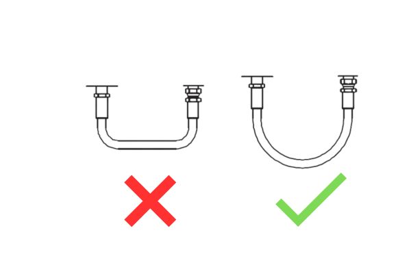
The bend radius of a hydraulic hose is not merely a geometric constraint; it is a fundamental design parameter that directly impacts the hose’s performance, durability, and safety. When a hydraulic hose is bent beyond its specified minimum bend radius, it undergoes excessive stress and strain, leading to a cascade of detrimental effects. This over-bending can cause the reinforcement layers within the hose—whether textile braid, wire braid, or spiral wire—to separate, kink, or even fracture. The inner tube can also suffer damage, leading to fluid leakage and contamination of the hydraulic system. Such damage often manifests as bend fatigue failure, a common culprit behind premature hose degradation and system downtime.
Proper bend radius adherence is crucial for several reasons:
- Preventing Premature Failure: The most significant benefit of respecting the minimum bend radius is the prevention of early hose failure. Hoses bent too tightly experience localized stress concentrations that accelerate material fatigue, leading to cracks, leaks, and ultimately, catastrophic rupture. This is particularly true for dynamic applications where hoses are subjected to constant flexing and pressure cycles. Adhering to the manufacturer’s recommended bend radius ensures that the hose operates within its elastic limits, distributing stress evenly and maximizing its service life.
- Maintaining Flow Efficiency: An improperly bent hose can restrict the flow of hydraulic fluid, leading to pressure drops, increased heat generation, and reduced system efficiency. Kinks or severe bends create turbulent flow patterns, which not only waste energy but can also contribute to cavitation and accelerated wear of hydraulic components. By maintaining an adequate bend radius, engineers ensure smooth, laminar flow, preserving system performance and energy efficiency.
- Ensuring System Safety: Hydraulic systems operate under high pressures, and a compromised hose poses a significant safety risk. A burst hose can release high-pressure fluid, causing severe injuries or property damage. By preventing bend fatigue and maintaining hose integrity, proper bend radius management directly contributes to a safer working environment for operators and maintenance personnel.
- Compliance with Industry Standards: Reputable hose manufacturers and industry organizations, such as the Society of Automotive Engineers (SAE) and the International Organization for Standardization (ISO), establish minimum bend radius specifications for various hose types and sizes. Adhering to these standards is not only a best practice but often a regulatory requirement, ensuring that hydraulic systems meet performance and safety benchmarks. Ignoring these guidelines can lead to non-compliance, warranty voidance, and potential legal liabilities.
In essence, the bend radius is a critical determinant of a hydraulic hose’s operational lifespan and the overall reliability of the hydraulic system. Overlooking this fundamental principle can lead to costly failures, reduced efficiency, and significant safety hazards. Therefore, a thorough understanding and diligent application of bend radius guidelines are indispensable for any professional involved in the design, installation, or maintenance of hydraulic systems.
Understanding Minimum Bend Radius: Definition and Measurement
The minimum bend radius (MBR) of a hydraulic hose is a crucial specification provided by manufacturers, representing the smallest radius to which a hose can be bent without causing damage or significantly reducing its service life. It is a fundamental parameter that installation engineers and designers must strictly adhere to.
Definition of Minimum Bend Radius
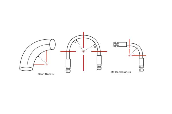
The minimum bend radius is typically measured to the inside edge of the hose bend, not the centerline. This distinction is important because the inner wall of the hose experiences the greatest compression, while the outer wall experiences the greatest tension during bending. The MBR ensures that neither the inner tube nor the reinforcement layers are subjected to stresses beyond their design limits, which could lead to kinking, collapse, or premature fatigue.
It’s important to differentiate between static and dynamic bend radii:
- Static Bend Radius: This applies to hoses that are installed in a fixed position and do not experience movement or flexing during operation. The static MBR is generally smaller than the dynamic MBR, as the hose is not subjected to continuous bending stress.
- Dynamic Bend Radius: This applies to hoses that are subjected to continuous or frequent flexing, bending, or movement during operation. Examples include hoses on robotic arms, excavators, or other machinery with moving parts. The dynamic MBR is always larger than the static MBR to account for the additional fatigue caused by repeated bending cycles. Manufacturers often specify a higher bend factor (e.g., 1.1 to 1.5 times the static MBR) for dynamic applications to ensure adequate service life.
How Minimum Bend Radius is Measured
The measurement of the minimum bend radius is a standardized process conducted by manufacturers under controlled laboratory conditions. While the exact methodology may vary slightly between manufacturers, the core principle remains consistent: determining the smallest radius at which the hose can be bent without exhibiting signs of damage or permanent deformation.
Common methods for measuring MBR involve:
- Visual Inspection: Bending the hose around a mandrel of a specific radius and visually inspecting for kinking, flattening, or distortion of the hose cross-section. The smallest radius at which no such damage occurs is considered the MBR.
- Pressure Testing: Bending the hose to a certain radius and then subjecting it to its maximum working pressure. If the hose can withstand the pressure without bursting or leaking, and without permanent deformation after pressure is released, that radius is considered acceptable. This process is repeated with progressively smaller radii until failure occurs, thereby identifying the MBR.
- Flow Rate Measurement: Bending the hose and measuring the fluid flow rate through it. A significant reduction in flow rate can indicate internal kinking or restriction, even if external damage is not immediately visible. The MBR is the point at which flow restriction becomes unacceptable.
It is crucial for users to rely on the manufacturer’s published MBR specifications, as these values are derived from rigorous testing and are specific to the hose’s construction, materials, and intended application. Attempting to determine the MBR empirically in the field without proper equipment or knowledge can lead to inaccurate assessments and potential hose failure.
Factors Influencing Hydraulic Hose Bend Radius
The minimum bend radius of a hydraulic hose is not a universal constant; it is a dynamic value influenced by several key factors related to the hose’s construction, materials, and intended application. Understanding these influencing factors is crucial for selecting the appropriate hose for a given application and ensuring its longevity.
Hose Construction and Reinforcement Layers
The internal structure and reinforcement layers are perhaps the most significant determinants of a hydraulic hose’s flexibility and, consequently, its minimum bend radius. Different types of reinforcement offer varying degrees of flexibility and pressure resistance:
- Textile Braid: Hoses reinforced with textile braids (e.g., cotton, polyester) are generally the most flexible and have the smallest bend radii. They are typically used in low-pressure applications.
- Wire Braid: Hoses with one or more layers of braided steel wire are common in medium to high-pressure applications. The number of wire braids directly impacts flexibility; a single wire braid hose (e.g., SAE 100R1) will be more flexible than a two-wire braid hose (e.g., SAE 100R2) of the same inner diameter. As the number of wire layers increases, the hose becomes stiffer, and its minimum bend radius increases.
- Spiral Wire: For very high-pressure applications, hydraulic hoses often feature multiple layers of spiraled steel wire (e.g., SAE 100R12, SAE 100R13). These hoses are designed for extreme pressures and are inherently less flexible than braided hoses, resulting in significantly larger minimum bend radii. The tighter the spiral, the less flexible the hose.
- Hose Material: The materials used for the inner tube and outer cover also play a role. Elastomeric materials like synthetic rubber (e.g., Nitrile, Neoprene) are common due to their flexibility and chemical resistance. Thermoplastic hoses, while offering good chemical resistance and often smaller outer diameters, can have different flexibility characteristics depending on the specific polymer used.
Inner Diameter (ID) of the Hose
There is a direct correlation between the inner diameter (ID) of a hydraulic hose and its minimum bend radius. Generally, the larger the inner diameter of the hose, the larger its required minimum bend radius. This is because a larger hose has a greater cross-sectional area, and bending it to a tight radius would induce more significant stress on its materials. For example, a 1-inch ID hose will have a considerably larger MBR than a 1/4-inch ID hose, even if both have the same reinforcement type.
Operating Pressure and Temperature
While not directly influencing the inherent minimum bend radius of the hose material, operating pressure and temperature can indirectly affect the effective bend radius in an application. Hoses operating under high pressure experience increased internal stress, which can exacerbate the effects of over-bending. Some manufacturers may recommend a slightly larger bend radius for hoses consistently operating at or near their maximum working pressure to extend service life. Similarly, extreme temperatures (both high and low) can affect the flexibility of the hose materials, potentially requiring adjustments to bend radius considerations. For instance, hoses can become stiffer in very cold environments, making them more susceptible to damage if bent too tightly.
Application Type (Static vs. Dynamic)
As discussed earlier, whether the hose is used in a static or dynamic application significantly impacts the required bend radius. Dynamic applications, where the hose is constantly flexing, demand a larger minimum bend radius to account for the continuous fatigue cycles. Ignoring this distinction is a common cause of premature hose failure in machinery with moving parts.
External Factors and Installation Practices
Improper installation practices can also lead to effective bend radii that are smaller than recommended, even if the hose itself is capable of tighter bends. Factors such as:
- Incorrect Hose Length: Using a hose that is too short can force it into tighter bends than intended.
- Improper Routing: Poor routing that creates sharp corners or twists can lead to localized over-bending.
- Lack of Bend Restrictors: In applications where hoses are prone to kinking or over-bending, the absence of bend restrictors or protective sleeves can contribute to premature failure.
Understanding these factors allows engineers to make informed decisions during the design and installation phases, ensuring that the selected hydraulic hose and its routing are appropriate for the specific application, thereby maximizing its lifespan and system reliability.
Calculating Minimum Bend Radius: Methods and Considerations
Calculating the minimum bend radius (MBR) for a hydraulic hose is not typically a calculation performed by the end-user or installer in the field. Instead, the MBR is a specification provided by the hose manufacturer, determined through rigorous testing and adherence to industry standards. The role of the installation engineer or designer is to adhere to this specified MBR, not to calculate it from scratch.
Manufacturer-Provided MBR
The most reliable and accurate source for a hydraulic hose’s minimum bend radius is the manufacturer’s technical data sheet or catalog. These documents will list the MBR for each specific hose type, size (inner diameter), and pressure rating. It is imperative to consult these specifications for every hose used in a hydraulic system. Ignoring these published values is a primary cause of premature hose failure.
Manufacturers typically express the MBR in inches or millimeters. For example, a specification might state: “Minimum Bend Radius: 4.0 inches.” This means that the hose should never be bent to a radius smaller than 4.0 inches, measured to the inside curve of the bend.
General Guidelines and Rules of Thumb (with Caution)
While manufacturer specifications are paramount, some general guidelines and rules of thumb exist, primarily for conceptual understanding or preliminary design. These should never replace the manufacturer’s data.
One common, albeit simplified, approach for estimating a static MBR is to multiply the hose’s inner diameter (ID) by a factor. This factor varies significantly based on hose construction:
- Single Wire Braid (SAE 100R1): Approximately 6 to 8 times the ID.
- Two Wire Braid (SAE 100R2): Approximately 8 to 10 times the ID.
- Multi-Spiral Wire (SAE 100R12, R13, R15): Can be 10 to 20 times the ID or more.
Example: If a hose has an inner diameter of 1 inch and a typical bend radius ratio of 8, its minimum bend radius would be 8 inches (1 inch * 8).
Important Caveat: These are very rough estimates and should only be used for initial planning. The actual MBR can be influenced by the specific materials, manufacturing processes, and exact reinforcement design, making manufacturer data indispensable.
Considerations for Dynamic Applications (Bend Factor)
For hoses in dynamic applications, where continuous flexing occurs, the effective MBR must be larger than the static MBR. Manufacturers often provide a bend factor” or “dynamic bend radius multiplier” to account for this. This factor typically ranges from 1.1 to 1.5.
Dynamic MBR = Static MBR * Bend Factor
For instance, if a hose has a static MBR of 5 inches and is used in a dynamic application with a bend factor of 1.2, the effective dynamic MBR for installation should be 6 inches (5 inches * 1.2). This ensures that the hose is not over-stressed during its operational cycles.
Practical Application and Measurement in the Field
Once the appropriate MBR is known, it must be correctly applied during installation. Here are practical considerations:
- Measuring the Bend Radius: To verify that an installed hose meets the MBR requirement, measure the radius of the innermost curve of the hose. This can be done using a flexible ruler or a bend radius gauge. Ensure that this measured radius is equal to or greater than the specified MBR.
- Avoiding Kinks and Twists: Even if the overall bend radius is sufficient, localized kinks or twists can severely damage the hose. Always route hoses smoothly, avoiding sharp turns or points where the hose might be pinched or twisted. The hose should never be twisted along its longitudinal axis during installation, as this can significantly reduce its pressure rating and lifespan.
- Using Bend Restrictors and Clamps: In applications where hoses are prone to kinking or over-bending, especially near fittings, bend restrictors can be used. These devices help maintain the hose’s natural curve and prevent it from bending beyond its MBR. Proper clamping and routing also prevent the hose from moving excessively and creating unintended tight bends.
- Considering Hose Length: Ensure that the hose length is adequate for the application. A hose that is too short will be forced into tighter bends, potentially violating the MBR. Conversely, an excessively long hose can create unnecessary slack, leading to abrasion or entanglement. The ideal hose length allows for natural bends that respect the MBR, accommodates system movement, and provides sufficient slack for thermal expansion/contraction and pressure surges.
- Proper Fitting Installation: Always use the correct fittings for the hose type and application. Ensure fittings are clean and free of debris. Apply proper torque specifications when tightening fittings to prevent leaks and avoid damaging the fitting or hose. Over-tightening can damage threads or deform sealing surfaces, while under-tightening leads to leaks.
By diligently applying these principles and always referring to manufacturer specifications, engineers can ensure that hydraulic hoses are installed in a manner that maximizes their service life and contributes to the overall reliability and safety of the hydraulic system
Best Practices for Installation and Maintenance
Proper installation and diligent maintenance are paramount to maximizing the lifespan of hydraulic hoses and ensuring the leak-free operation of hydraulic systems. Even with the correct hose and fittings, poor practices can lead to premature failure, costly downtime, and safety hazards. Adhering to these best practices will significantly enhance system reliability and longevity.
Hose Routing and Installation Best Practices
- Respect the Minimum Bend Radius (MBR): This is the golden rule. Always ensure that the actual bend radius in your installation is equal to or greater than the manufacturer’s specified MBR for both static and dynamic applications. Use bend radius calculators or templates if necessary during design and installation. Avoid forcing hoses into tight spaces that violate the MBR.
- Avoid Twisting the Hose: A common cause of premature hose failure is twisting during installation. Even a small twist (e.g., 7 degrees) can reduce hose life by up to 90% [citation needed, will add a reference here later]. Ensure that the hose is installed without any torsional stress. Use two wrenches when tightening fittings to prevent the hose from twisting. If the hose has a layline (a stripe running along its length), ensure it remains straight, not spiraled, after installation.
- Allow for Length Changes: Hydraulic hoses can change length under pressure (typically shortening or lengthening by 2% to 4%). Provide sufficient slack to accommodate these changes, especially in dynamic applications. Do not pull hoses taut between connection points.
- Protect from Abrasion: Hoses should be routed to avoid rubbing against other components, sharp edges, or abrasive surfaces. Use protective sleeves, clamps, and routing clips to prevent abrasion. If hoses must cross, use clamps or separators to prevent contact.
- Manage Heat: Route hoses away from high-heat sources like exhaust manifolds or hot engine components. Excessive heat can degrade hose materials, leading to premature failure. If proximity to heat is unavoidable, use heat shields or high-temperature resistant hoses.
- Avoid Kinking and Pinching: Ensure hoses are not kinked or pinched during installation or operation. Kinks severely restrict flow and damage the hose structure. Use proper hose length and routing to prevent kinking, especially near fittings.
- Use Proper Clamping: Secure hoses with clamps at appropriate intervals to prevent excessive movement, vibration, and abrasion. However, do not over-clamp or use clamps that are too tight, as this can restrict hose movement and cause localized stress.

Maintenance and Inspection
- Regular Visual Inspections: Periodically inspect all hoses and connections for signs of wear, abrasion, kinking, blistering, leaks, or corrosion. Pay close attention to areas near fittings and points of movement.
- Check for Leaks: Any sign of hydraulic fluid leakage, no matter how small, should be investigated immediately. Leaks indicate a compromised system and can escalate quickly.
- Monitor System Pressure and Temperature: Operating outside the specified pressure and temperature limits can accelerate hose and seal degradation. Ensure system gauges are functioning correctly.
- Replace Damaged Components Promptly: Do not attempt to repair damaged hoses or severely compromised fittings. Replace them with new, appropriate components. Patching a hose is a temporary and dangerous solution.
- Fluid Cleanliness: Maintain the cleanliness of the hydraulic fluid through proper filtration. Contaminated fluid can damage internal hose linings and abrade seals.
- Scheduled Replacement: Even without visible damage, hoses have a finite lifespan. Consider scheduled replacement based on manufacturer recommendations, operating hours, or environmental conditions, especially for critical applications.
By integrating these best practices into your installation and maintenance protocols, you can significantly extend the service life of hydraulic hoses and seals, ensuring the safe, efficient, and reliable operation of your hydraulic systems.
Conclusion
Understanding and diligently applying the principles of hydraulic hose bend radius and proper connector sealing are fundamental to the design, installation, and maintenance of reliable and efficient hydraulic systems. Adherence to these best practices transforms potential points of failure into robust, high-performing elements of any hydraulic circuit, ensuring long-term success and operational excellence.
If you have any hydraulic hose needs, contact us, Topa can provide the optimal hose products!
FAQ
What happens if I bend a hydraulic hose tighter than its minimum bend radius?
Bending a hydraulic hose tighter than its minimum bend radius can cause internal damage to the hose, leading to kinking, reduced flow, premature wear, and eventual failure due to fatigue.
How do I find the minimum bend radius for a specific hydraulic hose?
Always refer to the manufacturer’s technical data sheet or catalog for the precise minimum bend radius specifications for your specific hydraulic hose type and size.
Is the minimum bend radius the same for static and dynamic applications?
No, the minimum bend radius for dynamic (flexing) applications is typically larger than for static (fixed) applications to account for continuous fatigue cycles. Manufacturers often provide a ‘bend factor’ for dynamic use.
What is the most common cause of hydraulic hose failure?
While many factors contribute, improper installation, including exceeding the minimum bend radius and twisting the hose, is a very common cause of premature hydraulic hose failure.
Why are O-Ring Face Seal (ORFS) fittings preferred in many hydraulic applications?
ORFS fittings are highly favored for their superior leak-free performance, especially in high-pressure and vibration-prone applications, due to their soft, reliable O-ring seal that is resistant to over-tightening and vibration.
How important is fluid compatibility when selecting O-rings?
Fluid compatibility is critical; using an incompatible O-ring material with the hydraulic fluid can lead to seal degradation, swelling, shrinking, or hardening, resulting in leaks and premature failure.
References
[1] StrongFlex. Bend Radius Guidelines for Hydraulic Hose.
[2] Fluid Power Journal. Hydraulic Hose Maintenance.
[3] LinkedIn. What are the common types of hydraulic fitting seals?
[4] Royal Brass and Hose. Seal the Deal: Your Guide to O-Ring Types.
[5] Hose Assembly Tips. Minimum bend radius for hydraulic hoses.