As a quality manager, you are the gatekeeper of reliability. But a tiny, unseen defect in a hydraulic fitting can lead to system failure, putting your company’s reputation and safety at risk.
We guarantee hydraulic fitting quality by using a suite of precision inspection tools. This includes salt spray testers for corrosion resistance, profile projectors for dimensional accuracy, roughness testers for seal surface integrity, and hardness testers for material strength. These tools are key to our quality assurance process.
How Do We Verify Corrosion Resistance Over Time?
Your equipment operates in wet, salty, or humid environments. A fitting that rusts quickly will fail, causing leaks and downtime. This is unacceptable.
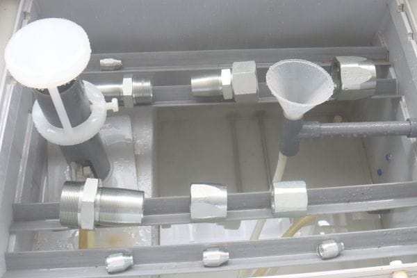
We use a salt spray tester to prove the corrosion resistance of our fittings. This machine creates an aggressive, corrosive environment, simulating years of harsh exposure in just a few days. It is the definitive test of our plating quality and ensures your fittings will not fail prematurely due to rust.
The plating on a hydraulic fitting is its first and most important line of defense against the environment. A simple visual check cannot tell you if the plating is thick enough or applied correctly. The salt spray test is a destructive but necessary process that provides clear, undeniable proof of a fitting’s long-term durability.
What Is a Salt Spray Test?
This test follows strict international standards like ASTM B117 or ISO 9227. It involves placing sample fittings into a sealed chamber. Inside, a heated, atomized solution of saltwater creates a dense, corrosive fog that is maintained for a specific duration. Technicians periodically inspect the fittings for any signs of corrosion. The goal is to see how many hours the plating can withstand the attack before the underlying steel begins to rust.
Why This Test Is Critical for Plating Quality
The test reveals hidden flaws in the electroplating process. A high-quality zinc or zinc-nickel plating forms a complete, non-porous barrier over the steel. If the plating is too thin, has microscopic pores, or was applied over a poorly cleaned surface, the salt fog will penetrate these weaknesses. This allows the saltwater to reach the base steel, initiating corrosion. It is a direct and unforgiving validation of our entire pre-treatment and plating process.
Interpreting the Corrosion Results
We look for two types of corrosion, and each tells a different story.
- White Rust: This is zinc oxide, a chalky white powder. It indicates that the sacrificial zinc layer is doing its job and actively corroding to protect the steel underneath. Some white rust is expected over time.
- Red Rust: This is iron oxide, the familiar red color of rust. The appearance of red rust is a failure. It means the corrosive agent has breached the plating and is now attacking the steel structure of the fitting.
Our quality standards are defined by the hours a fitting can endure before red rust appears.
| Test Duration (Neutral Salt Spray) | Observation | Plating Quality Assessment |
| 0-24 Hours | Red rust appears | Fail. The plating process is defective. Batch is rejected and quarantined. |
| 48 Hours | No red rust, minor white rust | Standard Pass. Suitable for general industrial use in controlled environments. |
| 72-96 Hours | No red rust | Good Quality. Pass for most outdoor equipment applications. |
| 240+ Hours | No red rust | Excellent. High-performance plating (e.g., Zinc-Nickel) for marine, offshore, or highly corrosive environments. |
How Do We Ensure Perfect Dimensional Accuracy?
The wrong angle on a flare or an incorrect thread pitch can make a fitting impossible to install or cause a persistent leak. These small dimensional errors lead to big problems.
We guarantee dimensional accuracy using profile projectors and advanced video measuring machines (VMM). These instruments magnify a fitting’s profile by up to 100 times, allowing our technicians to measure critical angles, radii, and thread forms with micron-level precision against design blueprints.

A hydraulic fitting is a complex geometric part. Its ability to seal under thousands of PSI depends on dimensions and angles that are often invisible to the naked eye. Relying on simple calipers is not enough. Profile projectors give us the power to see and measure these critical features, ensuring that every fitting we ship will mate perfectly with its corresponding part, every single time. This is fundamental to preventing assembly issues in the field.
From Silhouette to Data: The Profile Projector
A profile projector works by shining a bright, collimated light past a fitting. A series of lenses projects a highly magnified silhouette of the part onto a large screen. On this screen, a quality technician can use digital readouts or custom-made transparent charts (overlays) to measure dimensions. They can precisely check the 37-degree angle of a JIC flare, verify the root and crest of a thread, and measure the radius of a small chamfer. It is an intuitive and reliable method for 2D measurement.
Critical Dimensions We Scrutinize
Using these tools, we focus on the features that have the biggest impact on performance and safety. A deviation in any of these areas can lead to rejection of the part.
- Thread Form and Pitch: We check the thread angle (e.g., 60° for UN/UNF threads), pitch (distance between threads), and major/minor diameters. Errors here cause cross-threading or a loose fit.
- Sealing Cone Angle: For fittings like JIC, the 37° cone angle is paramount. We measure this to within fractions of a degree. An incorrect angle prevents the proper metal-to-metal line contact needed for a high-pressure seal.
- Concentricity and Runout: We ensure that features like the thread and the hex are perfectly centered relative to each other. Poor concentricity can make a fitting difficult to tighten with a wrench.
- Chamfers and Radii: These small, often overlooked features are critical for smooth assembly and for reducing stress concentrations that could lead to fatigue cracks over time.
How Do We Guarantee a Perfect, Leak-Proof Seal?
A fitting can be dimensionally perfect, but it will still leak if its sealing surface is too rough. Microscopic scratches on a flare cone create a ready-made path for high-pressure fluid to escape.
To prevent this, we use a surface roughness tester, also known as a profilometer. This highly sensitive instrument measures the microscopic peaks and valleys on a fitting’s critical sealing surfaces. This ensures the surface finish is smooth enough to create a perfect, leak-proof seal under pressure.

The seal of a metal-to-metal connection depends on two surfaces being so smooth that there are no gaps between them for fluid to pass through. For O-ring seals, the surface must be smooth enough not to damage the O-ring during installation. A visual inspection cannot judge this quality. The surface roughness tester provides a quantitative number, Ra (Roughness average), that tells us exactly how smooth a surface is, removing all guesswork from this critical aspect of quality.
Measuring the Invisible: Surface Roughness (Ra)
A surface roughness tester uses a stylus with a diamond tip, similar to a record player needle. This stylus is gently dragged across the surface being tested. As it moves, it follows the microscopic topography, rising over peaks and falling into valleys. The instrument’s electronics amplify this movement and calculate a value, most commonly the Ra value. Ra is the arithmetic average of the absolute values of the profile heights over the evaluation length. A lower Ra value means a smoother surface.
Why Smoothness is Non-Negotiable for Sealing
Imagine a magnified view of a metal surface. Even one that feels smooth to the touch looks like a mountain range at the microscopic level. On a sealing surface, these peaks and valleys create leak paths.
- Metal-to-Metal Seals (e.g., JIC Flare): When two such surfaces are pressed together, only the ‘peaks’ touch. High pressure can force fluid through the ‘valleys’. A very smooth surface minimizes these gaps.
- O-Ring Seals (e.g., ORB, ORFS): A rough groove face can abrade or cut the O-ring during assembly. It can also create a texture that the O-ring cannot perfectly conform to, allowing for slow leaks.
Our Machining and Polishing Targets
The required surface finish depends on the function of the surface. We hold our machining processes accountable to these specific targets.
| Fitting Surface | Typical Ra Target (µm) | Importance and Reason |
| 37° JIC Flare Cone | Less than 0.8 µm | Highest. This is the primary metal-to-metal seal. Must be extremely smooth. |
| ORFS Flat Face | Less than 1.6 µm | High. This is the surface the O-ring seals against. Must not damage the O-ring. |
| O-Ring Groove Face | Less than 1.6 µm | High. The surface that the O-ring is compressed against. Smoothness prevents leaks. |
| General Body Surface | 3.2 µm or higher | Low. Primarily aesthetic and relates to a quality feel. Does not affect sealing performance. |
How Do We Confirm the Fitting’s Material Strength?
A fitting made from a soft or incorrect grade of steel is a catastrophic failure waiting to happen. It can deform, stretch, or strip its threads during tightening or under pressure.
We confirm the material strength of every batch using a hardness tester. This device presses a hardened indenter into the fitting’s material with a precise force. By measuring the indentation, we can verify the material’s hardness, which directly relates to its tensile strength and ability to withstand high pressures and assembly torque.

As a quality manager, you know that a product is only as good as the raw materials used to make it. Hardness testing is our first line of defense. We use it to verify incoming raw bar stock before it ever enters our CNC machines. This prevents us from wasting time and resources making parts from substandard material. It is a quick, effective, and non-destructive way to ensure the fitting’s core mechanical properties are correct.
The Principle of Hardness Testing
Hardness is a material’s resistance to localized plastic deformation, such as a scratch or dent. A hardness tester quantifies this property. Common methods include:
- Rockwell (HRC/HRB): Measures the depth of an indentation made by a diamond cone or steel ball. It’s fast and widely used for steel. We use this for routine checks on our carbon steel fittings.
- Vickers (HV): Uses a diamond pyramid indenter. It is very precise and can be used on a wide range of materials, including the thin outer layer of plating.
The resulting number allows us to confirm that the material meets the specification, for example, 45# carbon steel or 316 stainless steel.
Why Hardness is a Proxy for Strength
For steels, there is a very strong correlation between hardness and tensile strength. A higher hardness value indicates a stronger material. This strength is crucial for hydraulic fittings.
- Resisting Pressure: The fitting body must be strong enough to contain thousands of PSI without stretching or deforming.
- Thread Integrity: During tightening, the threads are under immense stress. A material that is too soft will allow the threads to strip long before proper torque is reached.
- Durability: A harder material is more resistant to wear and damage from handling and repeated assembly.
This test assures us—and you—that the fitting has the fundamental strength to perform its job safely.
How Do These Tools Form Our Quality System?
Individual tests are useful, but their real power is unlocked when integrated into a comprehensive Quality Assurance (QA) system that covers the entire production lifecycle.
Our QA process connects these inspection tools at three critical stages: incoming material, in-process manufacturing, and final inspection. This creates a chain of quality control that ensures standards are met from the raw steel bar to the finished, packaged product. For a quality manager, this systematic approach is proof of a mature and reliable manufacturing process.

A robust QA system is proactive, not reactive. It’s designed to prevent defects from happening in the first place, and to catch them immediately if they do. This multi-stage inspection strategy ensures we are not just inspecting quality into the product at the end, but building it in from the very beginning. This methodical process is what separates a top-tier supplier from the rest.
Stage 1: Incoming Quality Control (IQC)
Before a single chip is cut, the raw material is inspected.
- Action: We take a sample from each new batch of carbon steel or stainless steel bar stock.
- Tools Used: The Hardness Tester is used to verify the material grade and strength. We may also use a spectrometer for chemical analysis.
- Purpose: To reject substandard raw materials before they enter our production flow, preventing waste and ensuring the foundation of the product is solid.
Stage 2: In-Process Quality Control (IPQC)
During the CNC machining process, our operators constantly monitor production.
- Action: At regular intervals (e.g., every hour or every 100 parts), the operator pulls a sample part directly from the machine.
- Tools Used:Profile Projectors and precision gauges are used at the workstation.
- Purpose: To catch any drift in machine settings or tool wear immediately. This prevents the production of a large quantity of out-of-spec parts.
Stage 3: Final Quality Control (FQC)
This is the final gate before a product is approved for shipment.
- Action: After the fittings are machined and plated, a random sample representing the entire batch is taken.
- Tools Used: The full suite is deployed. The Salt Spray Tester verifies plating. The Video Measuring Machine confirms all final dimensions. The Surface Roughness Tester checks sealing surfaces.
- Purpose: To provide a complete, final verification that the entire batch meets all engineering and quality specifications.
Conclusion
Our comprehensive use of salt spray, projection, roughness, and hardness testers is not optional; it is the core of our quality promise, ensuring reliability and giving you total confidence.
Whether you need standard parts or custom solutions, our team is ready to support you. Contact us today to request a quick quote and place your order with confidence.
FAQ
How often should hydraulic fitting quality tests be performed?
Routine batch testing is recommended. Each new material lot, every production run, and pre-shipment checks should all undergo inspection.
Can salt spray results predict real-world service life?
No test perfectly replicates field conditions, but salt spray results provide a reliable benchmark for corrosion resistance across industries.
Do stainless steel fittings require the same corrosion testing as plated steel?
Yes. Even stainless steel can corrode under harsh conditions, so accelerated corrosion testing is valuable for quality assurance.
What happens if a fitting fails hardness testing?
The batch is quarantined. Materials are re-analyzed, and only fittings meeting strength specifications proceed to machining and shipment.
Are third-party certifications available for hydraulic fitting quality?
Yes. Many manufacturers provide ISO, SAE, or CE certification reports as independent verification of testing standards.
Can custom fittings undergo the same quality checks as standard parts?
Absolutely. Custom fittings follow identical QA processes, ensuring their performance matches or exceeds standard product reliability.