Hydraulic cylinder sizing should not begin with the question, “What bore size should I use?” The first question is: How much force must the cylinder produce under actual operating conditions?
A cylinder that looks adequate on paper may still fail to move the load if the calculation ignores return-line backpressure, friction, acceleration, pressure loss or side loading. An oversized cylinder can also create problems by increasing oil consumption, installation space, moving mass and system cost.
Why a 40 mm Cylinder at 160 Bar Cannot Push an 8-Ton Load
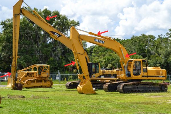
Consider a machine fitted with a hydraulic cylinder that has:
- 40 mm bore
- 160 bar operating pressure
- Required output of 8 metric tons-force
The piston area is: A=πD²/4
Where:
- D=40mm=0.04m
- A≈0.001257m²
A pressure of 160 bar equals 16 MPa. The theoretical extension force is therefore:
F=P*A
F=16,000,000×0.001257≈20,100 N
That is approximately 20.1 kN, or 2.05 metric tons-force.
An 8-ton-force load is approximately: 8,000×9.81≈78,500 N
The cylinder can therefore produce only about one-quarter of the required force—even before accounting for friction, backpressure and pressure losses.
Under ideal conditions, the theoretical bore required to produce 78.5 kN at 160 bar is: D=√4F/πP ≈ 79mm
However, 79 mm is only a theoretical minimum. It is not a final cylinder specification. The actual bore may need to be larger after considering:
- Rod-side backpressure
- Seal and guide friction
- Acceleration forces
- Pressure loss through valves and piping
- Load uncertainty
- Shock loading
- Cylinder pressure rating
- Piston rod stability
- Mounting alignment
Information Required Before Sizing a Hydraulic Cylinder
Collect the operating data before performing any calculations.
| Category | Information required |
| Load | Weight, pressing force, clamping force, friction and external resistance |
| Motion | Horizontal, vertical or inclined movement |
| Direction | Pushing, pulling or both |
| Dynamics | Constant speed, acceleration, deceleration and impact |
| Pressure | Actual cylinder inlet pressure, return pressure and pressure peaks |
| Stroke | Required travel and mechanism geometry |
| Speed | Extension speed, retraction speed and cycle time |
| Duty cycle | Cycles per minute, operating hours and holding time |
| Mounting | Flange, clevis, trunnion, foot or another arrangement |
| Space | Retracted length, extended length and port clearance |
| Environment | Temperature, dust, water, corrosion and outdoor exposure |
| Fluid | Mineral oil, water-glycol or another hydraulic fluid |
| Options | Cushioning, position sensing and load-holding requirements |
Step 1: Calculate the Required Cylinder Force
The cylinder must overcome more than the nominal load. Depending on the application, the total force requirement may include static load, acceleration, friction, backpressure and other external resistance.
Static load
Static load is the primary resistance when acceleration is not considered. Examples include:
- The weight of a lifted object
- Pressing force
- Clamping force
- Spring resistance
- Continuous process resistance
For a vertical load: Fg = m × g
Where:
- m is the mass in kilograms
- g is approximately 9.81 m/s²
Engineering documents should distinguish between mass and force. For example, 8,000 kg is a mass, while approximately 78.5 kN is its weight under normal gravity.
Acceleration force
When the cylinder must accelerate a moving mass, include the inertial force: Fa = m × a
A short cycle time or rapid acceleration can significantly increase the required force.
Shock loading requires additional evaluation. A sudden stop, collision or rapidly changing load cannot always be represented accurately by a simple constant-acceleration calculation.
Friction and mechanism resistance
Possible sources of resistance include:
- Linear guide friction
- Pivot friction
- Cylinder seal friction
- Contact friction
- Linkage resistance
- Misalignment
- External process forces
Using one fixed friction percentage for every application is unreliable. Whenever possible, use measured values, component data or a calculation based on the actual mechanism.
Return-line backpressure
During extension, pressure in the cap end pushes the piston forward. Pressure in the rod end creates an opposing force.
The approximate net extension force is:Fext = PA × Ap − PB × Aa − Ff
Where:
- PA is cap-end pressure
- Ap is full piston area
- PB is rod-end backpressure
- Aa is rod-side annular area
- Ff is friction and other mechanical resistance
This equation is more realistic than using only: F = P × A
Backpressure may be created by:
- Directional valves
- Flow control valves
- Counterbalance valves
- Return filters
- Undersized hoses or pipes
- Long return lines
A cylinder may fail to extend even when the cap-end pressure appears high enough if rod-side backpressure has not been included.
Design margin
A design margin may be necessary when the load is uncertain, shock is present or failure would have serious consequences.
There is no single safety factor suitable for every hydraulic cylinder application. The required margin should be based on:
- Load accuracy
- Shock severity
- Duty cycle
- Mounting arrangement
- Applicable regulations
- Company engineering standards
- Cylinder manufacturer data
- Consequences of failure
Avoid applying several overlapping allowances for friction, shock and safety without understanding what each one covers.
Step 2: Determine the Actual Available Pressure
The pump pressure rating is not automatically the pressure available at the cylinder.
The actual cylinder inlet pressure may be lower because of:
- Relief valve settings
- Valve pressure drop
- Hose and pipe losses
- Filter restriction
- Pump wear
- Oil temperature
- Simultaneous actuator operation
The relevant value is the pressure available at the cylinder port while the machine is performing the required operation.
Where possible, measure pressure close to both cylinder ports during the actual loaded cycle. Measuring both chambers helps identify whether return-side backpressure is reducing the net force.
It is also important to distinguish between:
- Normal working pressure
- Relief valve setting
- Maximum allowable cylinder pressure
- Transient pressure peak
- Test pressure
Step 3: Calculate the Required Cylinder Bore
Once the required force and effective pressure are known, calculate the theoretical piston area: A = F / P
Then calculate the bore: D = √(4F / πP)
Where:
- Fis force in newtons
- P is pressure in pascals
- A is area in square metres
- D is bore diameter in metres
Example: 50 kN at 200 bar
Assume the cylinder must produce a theoretical force of 50,000 N and the available pressure is 200 bar.
A pressure of 200 bar equals 20 MPa:
A = 50,000 / 20,000,000 = 0.0025 m2
This equals:
0.0025 m2 = 25 cm2
The theoretical bore is:
D = √[(4 × 0.0025) / π] ≈ 0.0564 m
Therefore, the calculated minimum bore is approximately 56.4 mm.
The next suitable standard bore may be 63 mm, depending on the selected cylinder series.
A 63 mm bore has a piston area of approximately 31.17 cm2. At 200 bar, its theoretical extension force is:
F ≈ 62.3 kN
This value must still be reduced by rod-side backpressure, friction and other system losses.
Why the calculated bore must be checked again
Rounding up to a standard bore does not complete the selection. Verify:
- Net extension force
- Net retraction force
- Required operating pressure
- Cylinder maximum allowable pressure
- Required oil flow
- Available installation space
- Rod buckling capacity
- Mounting capacity
A larger bore increases force but also increases oil consumption and may reduce speed if pump flow remains unchanged.
Standard Bore Does Not Mean Standard Pressure Rating
A 63 mm bore is available in several cylinder families, but bore size alone does not define the product’s pressure capability.
For example:
- ISO 6020 covers dimensional series for 16 MPa, or 160 bar, single-rod cylinders.
- ISO 6022 covers dimensional series for 25 MPa, or 250 bar, single-rod cylinders.
These standards primarily define mounting dimensions and interchangeability. They do not mean that every cylinder with a listed bore is suitable for the same pressure, mounting load or duty cycle.
Always confirm the specific product’s:
- Rated operating pressure
- Allowable pressure peaks
- Test pressure
- Bore and rod combination
- Mounting limitations
- Seal temperature range
- Cushioning capability
- Manufacturer application limits
A standard bore should make sourcing and replacement easier, but it does not replace engineering verification.
Step 4: Check Extension and Retraction Separately
A single-rod double-acting cylinder does not have the same effective area in both directions.
Extension Area
During extension, pressure acts on the full piston area:
Ap = πD2 / 4
Ignoring backpressure and friction:
Fext = PA × Ap
Retraction Area
During retraction, the piston rod occupies part of the pressurized area. The effective annular area is:
Aa = π(D2 − d2) / 4
Where:
D is cylinder bore.
d is piston rod diameter.
Ignoring cap-end pressure and friction:
Fret = PB × Aa
Because the annular area is smaller than the full piston area, a single-rod cylinder usually has:
- Lower force during retraction
- Higher speed during retraction at the same inlet flow
| Item | Extension | Retraction |
| Effective area | Full piston area | Annular area |
| Force at equal pressure | Higher | Lower |
| Speed at equal inlet flow | Lower | Higher |
| Main check | Push force and backpressure | Pull force and rod size |
Step 5: Select the Stroke and Check Mounting Geometry
Stroke is the distance the piston travels, but cylinder stroke should not be selected from linear distance alone.
Calculate the required movement
For a direct linear mechanism, confirm:
- Required working travel
- Mechanical end positions
- Installation tolerance
- Safety clearance
- Cushioning requirements
- Sensor positions
Additional stroke should not be used as a substitute for proper end cushioning or mechanical stops.
Check linkage geometry
If the cylinder operates a lever, linkage or pivoting arm, calculate stroke from the full mechanism geometry.
The relationship between cylinder travel and machine movement may change throughout the stroke. Measuring only the distance between two approximate mounting positions can result in insufficient travel, overtravel or an incorrect force angle.
Check retracted and extended length
Confirm that:
- The retracted cylinder fits inside the available space
- The extended cylinder reaches the required position
- Ports remain accessible
- Hoses do not stretch or interfere
- The rod connection can be assembled
- Maintenance access is available
Where installation length is limited but long travel is required, possible solutions include a telescopic cylinder, a revised mounting position or a redesigned linkage.
Step 6: Select the Piston Rod and Check Buckling
The piston rod must satisfy more than the retraction-force requirement. It may also need to resist:
- Compression
- Tension
- Buckling
- Thread stress
- Connection loads
- Surface wear
- Corrosion
- Minor unavoidable alignment errors
Why stroke-to-bore ratio is not enough
Ratios such as stroke divided by bore or stroke divided by rod diameter can be used as early warning indicators. They cannot provide a final buckling decision.
Buckling depends on:
- Rod diameter
- Unsupported compression length
- Extended position
- Mounting style
- End constraints
- Rod material
- Maximum compressive load
- Alignment
- Required safety margin
The basic Euler buckling relationship is:
Fcr = π2EI / (KL)2
Where:
- E is the material’s elastic modulus
- I is the rod’s second moment of area
- L is unsupported compression length
- K is an effective-length factor based on end constraints
- Fcr is the ideal critical buckling load
The ideal Euler result should not be used directly as the allowable working load. Actual cylinder selection should follow the manufacturer’s rod selection chart or an approved engineering calculation that includes the required safety margin.
Ways to improve buckling resistance
If the calculated rod capacity is insufficient, consider:
- Increasing rod diameter
- Selecting a larger cylinder series
- Reducing unsupported length
- Changing the mounting arrangement
- Adding a stop tube
- Improving external guidance
- Reorienting the cylinder
- Reducing the maximum compressive load
A larger bore alone does not guarantee that the piston rod is safe.
Step 7: Calculate Cylinder Speed and Required Flow
Cylinder speed is determined by flow and effective area:
Q = A × v
Using common hydraulic units:
Q (L/min) = A (cm2) × v (cm/s) × 0.06
Example: 63 mm Bore at 200 mm/s
A 63 mm bore has a piston area of approximately 31.17 cm2.
If the required extension speed is 200 mm/s, or 20 cm/s:
Q = 31.17 × 20 × 0.06
Q ≈ 37.4 L/min
The cylinder therefore requires approximately 37.4 L/min of theoretical cap-end inlet flow.
Actual system flow may need to account for:
- Pump volumetric efficiency
- Valve leakage
- Cylinder leakage
- Oil temperature
- Acceleration requirements
- Flow-control losses
Calculate all four flow conditions
A complete calculation should include:
- Cap-end inlet flow during extension
- Rod-end return flow during extension
- Rod-end inlet flow during retraction
- Cap-end return flow during retraction
Return flow can be higher than pump inlet flow because the two cylinder chambers have different areas.
If the valve and return piping are selected only from pump flow, the system may develop excessive backpressure, heat and speed loss.
Do not select a valve from nominal flow alone
Check the valve’s pressure-drop-versus-flow curve under the relevant oil viscosity and temperature.
Valve selection should consider:
- Required flow in both directions
- Return flow
- Allowable pressure drop
- Working pressure
- Oil viscosity
- Port size
- Spool configuration
- Metering requirement
High pressure loss wastes energy as heat and also reduces the pressure available to move the load.
Step 8: Check Seals, Temperature and Duty Cycle
A hydraulic cylinder that meets the force and speed requirements can still fail early if its materials and seals do not match the application.
Fluid compatibility
Specify the hydraulic fluid, such as:
- Mineral hydraulic oil
- Water-glycol fluid
- Fire-resistant fluid
- Biodegradable hydraulic fluid
- Another special medium
Seal compatibility should be confirmed for the exact fluid and temperature range.
Operating temperature
Temperature affects:
- Oil viscosity
- Internal leakage
- Seal friction
- Seal life
- Pump efficiency
- Valve pressure loss
- Speed stability
The cylinder should be checked for both cold start and maximum stabilized operating temperature.
Duty cycle
A cylinder operating several times per day has different requirements from one cycling continuously in an automated production line.
Provide the supplier with:
- Cycles per minute or hour
- Operating hours per day
- Holding time under pressure
- Frequency of direction changes
- Expected service life
- Shock or emergency-stop conditions
Cushioning
A fast-moving cylinder may contain significant kinetic energy near the end of its stroke.
Without suitable deceleration, the system may experience:
- Pressure spikes
- Noise
- Mounting damage
- Piston or end-cap damage
- Hose vibration
- Reduced service life
Depending on the application, the solution may include cylinder cushioning, external flow control, proportional control or mechanical deceleration.
Common Hydraulic Cylinder Sizing Mistakes
Using pump nameplate pressure
Pump rated pressure does not equal the actual pressure available at the cylinder. Use the pressure measured or calculated at the actuator during the loaded operation.
Ignoring return backpressure
Rod-side backpressure reduces extension force. Check the return valve, filter, hoses, piping and any counterbalance or flow-control valves.
Calculating extension only
A cylinder may have enough extension force but insufficient retraction force. Calculate both directions separately.
Assuming a larger bore is always safer
A larger bore increases force, but it also increases:
- Required flow
- Oil volume
- Cylinder size
- Moving mass
- Return flow
- Cost
The correct bore is the one that meets the force requirement while remaining compatible with pressure, flow, speed and installation constraints.
Ignoring piston rod buckling
Long-stroke cylinders under compression require a proper rod stability check. Bore size alone does not determine buckling resistance.
Allowing the cylinder to carry side load
Hydraulic cylinders are designed primarily for axial loading. The machine structure should provide the required external guidance.
Selecting valves from rated flow only
A valve may pass the required flow but create excessive pressure loss. Check the manufacturer’s pressure-drop curve.
Ignoring temperature and duty cycle
High temperature and continuous cycling can increase leakage, reduce viscosity and shorten seal life. Provide realistic operating conditions when specifying the cylinder.
Conclusion
Before ordering a standard or custom hydraulic cylinder, prepare a complete application data sheet covering load, actual pressure, backpressure, stroke, speed, mounting and operating environment. The final specification should then be reviewed against the selected manufacturer’s cylinder data and application limits.
Frequently Asked Questions
What bore is required to produce 8 tons at 160 bar?
Under ideal conditions, 8 metric tons-force is approximately 78.5 kN. At 160 bar, the theoretical minimum bore is about 79 mm.
The final bore will normally need to be larger after accounting for backpressure, friction, dynamic loading, pressure losses and the required design margin.
What safety factor should be used for a hydraulic cylinder?
There is no universal value for every application. The appropriate margin depends on load uncertainty, shock, mounting, duty cycle, applicable standards and the consequences of failure.
Safety-critical lifting or personnel-related equipment requires formal engineering and compliance with applicable regulations.
Is a larger hydraulic cylinder bore always better?
No. A larger bore produces more force but requires more oil flow, occupies more space and may reduce speed. It can also increase cost and return-line flow.
Why is cylinder retraction force lower than extension force?
During retraction, the piston rod reduces the effective pressure area. The resulting annular area is smaller than the full piston area used during extension.
How can piston rod buckling be prevented?
Check rod diameter, effective compression length, mounting constraints and maximum load. Possible solutions include a larger rod, a different mounting style, a stop tube, improved external guidance or a larger cylinder series.
Can a smaller cylinder solve a low-speed problem?
A smaller bore moves faster at the same flow, but it also produces less force. Changing bore size requires a complete force, pressure, rod and stability review.