One-piece fitting stem length affects hose retention through the portion of the stem that actually engages the hose inside the crimped ferrule, not through the visible or total stem dimension alone. The effective engagement zone helps transfer axial load among the stem, inner tube, reinforcement, ferrule, and compressed hose structure. If that zone is poorly aligned or incompletely occupied, the assembly may not behave as its outside dimensions suggest. This article explains the load path, separates stem design from insertion error, and shows what evidence is needed before judging one-piece fitting stem length hose retention. Validated hose, fitting, and crimp data remain the final authority.
Total Stem Length Is Not Effective Engagement Length
The first design question is not “How long is the stem?” but “Which part of the stem is surrounded by the hose and supported by the intended crimp zone?” Overall length can include a lead-in, serrated area, smooth transitions, internal flow features, and portions that do not contribute equally to retention.
Locate the engaged boundaries
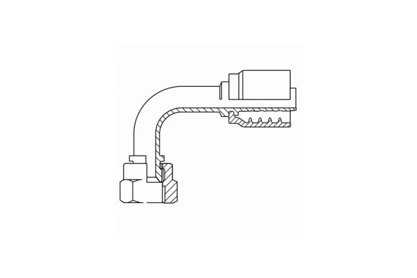
Effective engagement begins where the inserted hose starts participating in controlled contact with the stem and ends where the designed load-transfer region ends. A nose or lead-in may guide insertion without carrying the same load as the main stem profile. Likewise, a stem section extending beyond the compressed ferrule region may be inside the hose but outside the intended retention zone.
The measurement therefore needs common reference planes. A drawing review should identify the stem end, the hose stop or insertion reference, the beginning and end of the hose-side profile, and the ferrule region intended to be compressed. Comparing only an overall stem dimension can hide a shift in any of those boundaries.
Treat length as a relationship
Stem length has meaning only beside ferrule length, insertion position, hose construction, and the specified crimp location. Two fittings can have similar overall stems but different effective engagement because their lead-ins, stops, serrations, or ferrule positions differ. Conversely, two different overall lengths may create similar functional engagement in their respective approved systems.
This is why a dimension cannot prove pull-off resistance. Geometry indicates where load may be transferred; validated assembly testing establishes whether the complete combination provides the required retention under its defined conditions.
Visualize the Hose Layers Around the Stem
A useful verbal cross-section starts at the centerline and moves outward: flow passage, metal stem wall, hose inner tube, reinforcement, hose cover, and ferrule. Crimping changes contact and compression across these layers, creating a coupled structure rather than a stem acting alone.
Follow a radial slice
Imagine drawing a thin radial line from the bore through the finished assembly. The line first crosses the stem wall. Immediately outside it, the inner tube has conformed to the hose-side stem profile. Beyond the tube, the reinforcement has been compacted within limits defined for that hose construction. The cover occupies the next layer, and the ferrule provides the outer boundary that holds the compressed stack.
Each layer has a different job. The stem supports the inside of the hose end, the tube maintains fluid containment, the reinforcement carries much of the pressure-related structural load, and the ferrule applies and maintains the designed compression. Retention develops from their interaction; it is not a hook created by one metal feature.
Extend the slice along the axis
Now move that radial slice from the stem end toward the fitting body. Contact conditions change along the length. Near the lead-in, engagement may be gradual. Across the principal crimp region, compression and mechanical interlock develop. Near an edge or transition, the load path changes again. This longitudinal picture is the load-transfer-zone diagram in words.
The important design question is whether the hose layers, stem profile, and ferrule compression overlap in the intended region. A long stem with only partial ferrule overlap does not automatically create a long effective load path.
Engaged Length Shapes the Axial Load-Transfer Zone
Axial retention depends on distributing a tendency to pull the hose away from the fitting across a controlled length. Effective engagement gives the assembly room to transfer that load progressively through contact, friction, material deformation, and mechanical interlock within the validated crimp system.
Load enters and spreads
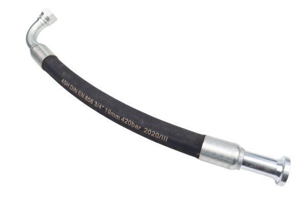
An axial load in the hose is carried primarily through its reinforcement and surrounding structure. Near the fitting, that load must move into the compressed region and then into the stem and fitting body. The ferrule supplies radial restraint while the hose conforms to the stem. A suitably coordinated engagement zone spreads this transfer instead of forcing it through a narrow local band.
This does not mean every point along the stem carries equal load. Local geometry, hose construction, ferrule compression, and transitions can change the distribution. Engineering review should therefore look for continuity of the complete load path rather than count serrations or compare one linear dimension.
Geometry conditions have different consequences
| Geometry condition | Likely mechanical consequence | What must be verified |
| Effective engagement is too short for the intended system | Load may be concentrated in a limited region, reducing the intended retention margin | Correct part series, insertion position, ferrule overlap, and validated pull-off evidence |
| Engagement is coordinated with stem and crimp design | Load can transfer across the designed hose-side region | Approved hose, fitting, ferrule, die, machine, and current crimp specification |
| Stem is longer than the functional crimp zone requires | Added length may not add useful retention and may affect tube support, flow entry, or hose flexibility | Drawing intent, hose response, section evidence, and complete assembly validation |
Too Short, Suitably Engaged, and Unnecessarily Long
Length comparisons should be framed as functional conditions rather than as a ranking from weak to strong. A stem can be too short for one system, correctly engaged in another, or longer than necessary without delivering additional retention.
When engagement is limited
If the active stem profile and compressed ferrule overlap across only a limited region, axial transfer may become more localized. The hose may also be sensitive to small insertion errors because a minor position change represents a larger share of the available engagement. These are reasons to investigate, not proof that a particular failure will occur.
A short visual stem is not automatically deficient. Compact designs can use different profiles, ferrule geometry, and hose constructions. The relevant evidence is the approved combination and its verified performance, not a comparison with a longer-looking fitting from another family.
When extra length stops helping
A longer stem may extend support farther into the hose, but it can also move the hose tangent point, stiffen a longer end region, or place stem features outside the ferrule’s effective compression. If the added portion does not participate in the designed crimp load path, it should not be counted as extra retention.
Longer geometry can also change insertion effort or how the inner tube passes over successive features. None of these effects can be judged from length alone. The safest conclusion is that suitable engagement is system-specific and must be confirmed with current hose, fitting, and crimp data.
Ferrule Length and Crimp Zone Must Align With the Stem
The stem and ferrule form opposing boundaries around the hose layers, so their active regions must be reviewed together. Retention-sensitive geometry is created by overlap among effective stem engagement, intended ferrule compression, and the reinforcement zone—not by either metal part in isolation.
Compare the longitudinal regions
On a section drawing, mark the hose insertion endpoint, stem profile limits, ferrule rear and front transitions, and the portion the dies are intended to compress. The principal overlap is where the stem supports the inside while the ferrule restrains the outside. A mismatch can leave part of the stem weakly supported or place compression where the stem geometry was not intended to receive it.
Ferrule ends also matter. Bell-mouth or transition regions may manage the change from compressed to uncompressed hose, but they are not automatically equivalent to the fully crimped region. Counting the entire ferrule length as effective crimp length can exaggerate the apparent engagement.

Keep crimp data in control
It is unsafe to extend a crimp simply to “use more stem” or to shorten the crimp because a stem looks compact. Changing the compressed region alters how metal and elastomer deform and may create edge loading or miss the designed load path. Die selection, crimp position, and final verification must follow approved data.
When comparing designs, request drawings that use consistent datums and identify functional regions. That makes the discussion about alignment and overlap rather than about whichever component has the largest overall dimension.
Stem Design Length and Insertion Depth Are Different Variables
Stem length belongs to the fitting design; insertion depth describes where the hose was placed on that design during assembly. They are frequently confused because both affect the amount of stem inside the hose, but the corrective action is completely different.
Design does not correct assembly position
A suitable stem cannot provide its intended engagement if the hose stops short. The resulting assembly may leave part of the active profile unoccupied and may shift the reinforcement relative to the ferrule. Conversely, pushing a hose beyond the intended stop is not a valid way to increase engagement and may disturb the designed internal relationship.
Insertion marks can help indicate movement relative to an external reference, but a mark alone does not prove complete insertion, correct part identity, or proper internal alignment. Its location and use must follow the approved assembly method.
Separate the investigation records
For a design question, record stem dimensions, functional profile limits, ferrule position, and drawing references. For an assembly-position question, record the hose preparation, insertion reference, mark position, stop condition, and evidence collected before crimping. Mixing these records can lead a team to change tooling or parts when the actual issue was process control.
If insertion is difficult, do not force the hose into place. Stop and verify hose ID, hose series, fitting series, stem condition, preparation method, and current assembly instructions before crimping.
What a Sectioned Assembly Can and Cannot Confirm
A properly prepared section can reveal whether the hose, stem, and ferrule occupy the expected relative positions. It is strong geometric evidence, but it is destructive, local, and unable by itself to prove retention performance.
Evidence visible in a section
A longitudinal section may show the insertion endpoint, overlap between the crimped ferrule and stem profile, local inner-tube conformance, reinforcement position, and transitions at ferrule edges. Multiple views can also reveal whether the observed relationship is reasonably consistent around the circumference.
Preparation artifacts must be considered. Cutting, grinding, polishing, or releasing residual stresses can smear rubber, disturb wires, separate layers, or create marks that resemble damage. The inspection method and section location should be documented so reviewers can distinguish original assembly evidence from preparation effects.
Limits of visual interpretation
A good-looking section does not establish pull-off resistance, impulse performance, pressure capability, or compatibility. It samples a small part of one assembly after destructive preparation. Retention depends on material behavior and complete-system validation that a static image cannot reproduce.
Use section inspection to answer geometric questions and to guide further investigation. Pair it with verified part identification, assembly records, measurement data, and applicable validation results rather than treating the section as final approval.
Design-review sequence for stem-length questions
Review stem-length concerns by moving from identity to geometry, then to assembly position and performance evidence. This order prevents a misleading overall dimension from driving an unsafe conclusion.
Establish the geometry and process
First confirm the hose manufacturer, series, construction, ID, and dash size; then confirm the fitting and ferrule series. Obtain controlled drawings and mark the stem end, hose stop, active profile, ferrule transitions, and intended crimp region. Verify that the specified insertion method and crimp procedure match that exact combination.
Next compare effective engagement, not just overall length. Check whether the hose occupies the intended stem region and whether the active ferrule compression overlaps it. Review sectioned evidence only with its preparation method and section location recorded.
Close with performance evidence
Finally compare the configuration with current manufacturer data and applicable assembly validation, including retention testing where the approved qualification plan requires it. Do not infer performance from the same hose dash, the number of serrations, or a longer stem borrowed from another family.
If evidence conflicts, quarantine the affected parts or assemblies and resolve identity, drawing revision, insertion, tooling, and measurement questions before use. The outcome should be a traceable decision about one defined hose-and-fitting system.
Conclusion
Effective hose engagement, not the largest overall dimension, is the useful basis for reviewing stem length. The stem, inner tube, reinforcement, ferrule, and compressed region must create a continuous load-transfer path, while insertion must place the hose in the designed position. A longer stem may add support, add no functional overlap, or change hose behavior; a shorter-looking stem may still be correct within a validated system. Use controlled drawings to map functional boundaries, inspect sections only as geometric evidence, and keep design length separate from insertion error. Before approving a change, prepare the exact hose and fitting identities, ferrule and crimp-zone information, insertion records, and applicable validation results for the one-piece fitting stem length hose retention review.
FAQ
Is a long stem always better than a short stem for hose retention?
No, a longer stem is not automatically better. Only the portion coordinated with the hose, ferrule, and intended crimp region contributes to the validated load path, and extra length may change other assembly conditions.
Does an insertion mark prove the hose reached the correct depth?
No, an insertion mark is only one process-control reference. Its meaning depends on the approved marking method, correct part identity, and confirmation that the hose reached the intended stop without moving before crimping.
Can fittings with the same hose dash use the same stem engagement?
No, the same dash size does not establish equal engagement or compatibility. Hose construction, fitting series, ferrule design, stem profile, and current crimp data must all match the approved combination.
Is pull-off testing enough to approve a different stem length?
No, pull-off testing is only one part of a defined validation plan. The review may also require dimensional, assembly, pressure, impulse, and application evidence specified by the responsible manufacturer or engineering authority.
Can section inspection prove that stem length is correct?
No, a section can confirm local geometry but cannot prove complete performance. Use it with controlled drawings, assembly records, repeatable preparation, and applicable validation results.