One-piece fitting ferrule length matters because the portion actually compressed controls how radial load is distributed along the hose end and how that region overlaps the supporting stem. Overall sleeve length alone is a poor comparison: bell-mouth areas, uncrimped transitions, retention features, and body-side geometry may occupy part of the visible ferrule. The effective crimp length is the region designed to transfer compression through the cover and reinforcement toward the stem. If that zone is misplaced or compared across unrelated fitting families, a similar-looking ferrule can create a very different assembly.
Overall Ferrule Length Is Not Effective Crimp Length
The functional question is how much of the ferrule is intended to receive controlled die compression, not how long the metal sleeve appears on a ruler. Overall length includes regions that manage entry, transitions, attachment, or clearance and may not share the same final geometry.

Establish consistent reference points
A meaningful drawing identifies the ferrule rear edge, hose-entry transition, start of the principal crimp region, end of that region, front transition, and relationship to the fitting body. The dimension between outside edges is useful for packaging and identification, but it does not automatically describe the compressed load-transfer zone.
The crimp specification may also define measurement locations that differ from overall sleeve boundaries. Inspectors should not assume the dies contact every visible millimeter or that every contacted area reaches the same final diameter. Die shape, ferrule profile, and machine setup determine the actual compression envelope under approved data.
Compare function rather than appearance
Two ferrules can share a similar outside length while using different bell mouths, wall profiles, grooves, or front-end transitions. Their effective crimp lengths may therefore differ. A shorter-looking ferrule may still provide the intended compressed region within its validated system, while a longer-looking sleeve may devote more length to transitions.
Cross-family comparisons require controlled drawings and exact part identities. Hose size, fitting series, ferrule design, stem geometry, and crimp data must be reviewed together before any dimensional difference is interpreted as stronger, weaker, or interchangeable.
Begin at the Rear Edge and Hose Entry
The longitudinal journey starts where the hose enters the ferrule. This rear region manages the change from free hose to constrained hose and can influence how abruptly bending and compression are introduced near the assembly end.
Rear transition and bell mouth
A bell mouth or tapered entry can provide clearance and a gradual transition from the ferrule to the hose cover. It may reduce a sharp metal edge acting directly against a hose that bends near the fitting, but its exact purpose and geometry are series-specific. It should not be counted automatically as fully effective crimp length.
The rear edge deserves inspection for burrs, deformation, and an unintended sharp contact condition. After crimping, the transition should be interpreted against the approved design rather than against a generic expectation. A visibly open bell mouth may be intentional; an irregular or collapsed entry may indicate a different issue.
Compression begins progressively
Moving forward from the entry, ferrule contact with the hose generally increases toward the principal compressed region. The hose cover and reinforcement experience a change from their free state to a constrained state. An abrupt transition can concentrate local deformation, while a controlled transition helps the assembly enter the main crimp zone more gradually.
This edge behavior matters even though it may not dominate axial retention. Repeated hose movement, routing, and bend location can make the rear boundary mechanically important. The hose manufacturer’s bend-radius and routing instructions still control; a bell mouth does not permit bending immediately against the fitting.
Through the Main Crimped Sleeve
The central ferrule region provides the principal outer restraint around the hose layers. Its effective length helps determine how compression and axial load transfer are spread, but the distribution is not necessarily uniform from one end to the other.

Radial compression across the length
As dies close according to approved settings, the ferrule wall moves inward and transmits radial force through the cover and reinforcement. The hose structure compacts around the stem. Material properties, wall geometry, die profile, and internal support influence the final state at each longitudinal position.
A longer effective compressed region may distribute interaction over more length, but that statement cannot be converted into a universal rule that longer is safer. If added length falls outside the useful stem overlap, changes transition behavior, or belongs to an incompatible geometry, it may not add effective load transfer.
Region-by-region interpretation
| Ferrule region | What happens there | Inspection concern |
| Rear edge and entry | Free hose begins transitioning into sleeve constraint | Burrs, collapse, sharp contact, or incorrect hose bend location |
| Rear compression transition | Radial constraint increases toward the main zone | Abrupt deformation, die misplacement, or unintended edge loading |
| Principal crimp region | Ferrule maintains compression through hose layers toward the stem | Diameter location, roundness, surface damage, and alignment with stem engagement |
| Front compression transition | Load path changes approaching the fitting body | Local over-compression, missed overlap, or stress concentration |
| Front edge and attachment area | Ferrule geometry joins or is retained with the fitting assembly | Distortion, cracking, interference, or incorrect part construction |
Approach the Front Transition and Fitting Body
Near the front of the ferrule, compression changes as the sleeve approaches its attachment or retained relationship with the fitting. This region must transfer load without relying on an abrupt, uncontrolled boundary.
Front-edge load changes
The inner stem may change section near the fitting body, and the ferrule may have a step, groove, taper, or uncompressed attachment feature. The surrounding hose is therefore moving from the principal crimp zone toward a different constraint condition. Local geometry can alter how radial and axial loads pass through the joint.
An abrupt compression transition deserves attention because it may concentrate deformation into a narrow band. That does not mean every visible line or profile change is a defect. Inspectors need the controlled part drawing, die-contact region, and sectioned geometry to determine whether the observed transition matches design intent.
Do not extend compression by guesswork
Moving the crimp toward the body to capture more ferrule length can compress a region not designed for die closure. It may distort attachment features, concentrate load, or place hose material against an unsuitable stem transition. Moving the crimp rearward can miss the intended front overlap.
Operators must use the approved die, machine, positioning method, and current crimp data. A visual preference for a longer or more centered crimp is not a valid reason to change the specified zone.
Ferrule Length Must Overlap Stem Engagement
The ferrule creates the outer compressed boundary while the stem supports and profiles the inside. Effective retention requires the intended ferrule compression to overlap the functional stem engagement region through the hose structure.
Map the opposing surfaces
On a longitudinal section, mark the hose insertion endpoint and the active stem profile. Then mark the ferrule’s principal compressed region and its transitions. The useful load-transfer zone is not simply either individual length; it is the designed relationship where the hose is constrained between them.
If the ferrule extends beyond stem support, part of the compressed hose may experience a different internal boundary. If the stem extends beyond the ferrule’s effective compression, that extra stem length may support the tube without contributing equally to ferrule-mediated retention. Both can be intentional, but they require design evidence.
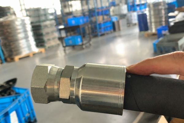
Keep the hose reinforcement in the review
The reinforcement carries much of the hose’s structural load, so its location and response matter inside the overlap. Cover thickness, reinforcement construction, tube properties, and skive or no-skive preparation affect how ferrule movement reaches the stem interface.
The same dash size does not guarantee the same layer thicknesses or deformation path. This is why ferrule length and stem length cannot establish compatibility without the precise hose series and validated crimp combination.
Misaligned Crimp Zones Change the Intended Load Path
A ferrule may be the correct part yet still be crimped in the wrong axial position. When die contact does not align with the intended sleeve region, the assembly can show acceptable-looking local diameter while missing the designed longitudinal relationship.
Rearward or forward displacement
A rearward-shifted crimp may overwork the entry transition and leave the front functional region insufficiently compressed. A forward-shifted crimp may load the attachment side, miss rear transition control, or act where stem geometry changes. Exact consequences depend on the design, so position evidence should guide investigation without inventing a universal failure pattern.
Positioning errors can arise from incorrect tooling references, wrong ferrule identity, incomplete insertion, inconsistent stops, or misunderstood machine instructions. Inspect the whole sequence rather than compensating with a different final diameter.
Outside diameter is incomplete evidence
A diameter measurement reports size at a selected location and orientation. It does not prove that the die contacted the intended axial region, that the hose reached the correct insertion depth, or that compression is distributed as designed. Roundness and location need to be recorded with the value.
Section inspection can show overlap and local layer response, but it remains destructive and limited. Combine it with machine records, tooling identity, part traceability, insertion controls, and applicable validation data.
Cross-family ferrule comparisons can mislead
Ferrules from different one-piece fitting families may look alike while serving different hose constructions and stem profiles. Similar outside length, finish, or dash marking does not establish the same effective crimp zone or interchangeability.
One family may use a longer entry transition, another a different attachment feature, and another a distinct wall profile across the main zone. Die geometry and final measurement location can also differ. Even when the same nominal hose size appears in both catalogs, the surrounding system may be unrelated.
Do not swap ferrules, extend or shorten crimp zones, or borrow settings based on visual comparison. A one-piece fitting is supplied with the body or stem and ferrule preassembled, attached, or retained together; separating that relationship or substituting a sleeve changes the defined assembly.
For purchasing or inspection comparisons, request part-revision drawings that label functional regions, identify the approved hose series, and state the applicable crimp procedure. This turns a visual comparison into a traceable engineering review.
Dimensional Review Workflow for Ferrule-Length Differences
Review length differences in a fixed order: identity, reference geometry, active regions, assembly position, and performance evidence. This prevents overall length from becoming a false acceptance criterion.
First confirm fitting series, ferrule identity, hose manufacturer, hose series, construction, ID, and dash size. Compare controlled drawings from common reference planes. Mark the rear entry, principal crimp region, front transition, stem engagement, hose stop, and specified measurement location.
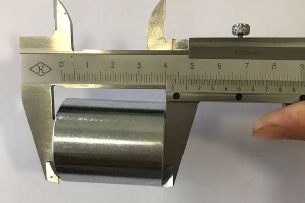
Review identity, geometry, process, and evidence
Next verify the actual process: hose preparation, insertion depth, crimp-position reference, die set, machine, current specification, and measurement method. Record diameter location and orientation rather than keeping an unlabeled number. Use a section only when its preparation and inspection plan can answer a defined overlap question.
Finally compare the exact combination with approved compatibility and validation evidence. If geometry, records, or section evidence conflict, quarantine the affected assemblies and investigate rather than adjusting crimp length. No universal ferrule length can replace this system-level review.
Conclusion
Ferrule length is useful only when its functional regions are separated from its overall metal envelope. From the rear entry through the principal compressed sleeve to the front transition, each region changes how the hose moves from free structure into a constrained load-transfer zone. Effective compression must align with stem engagement and the reinforcement it is intended to support. Similar-looking ferrules can have different active lengths, and an acceptable diameter cannot prove correct axial position. Before comparing or changing a design, prepare controlled ferrule and stem drawings, exact hose identity, insertion and crimp-position records, die and machine information, measurement locations, and applicable validation results. That evidence makes a one-piece fitting ferrule length review about function rather than appearance.
FAQ
Does overall ferrule length equal effective crimp length?
No, overall length may include entries, transitions, and attachment features. The effective crimp length is the region intended to receive controlled compression under the approved design.
Can the crimp length be changed to use more of the ferrule?
No, not by operator judgment. Extending or shortening the compressed region can load unintended geometry and must not occur outside approved crimp data and validated procedures.
Is the bell-mouth area part of the measured crimp diameter?
Not necessarily, because its function and measurement treatment are series-specific. Use the exact location and method stated in current manufacturer data.
Do ferrules for the same hose dash have the same effective length?
No, dash size does not define ferrule geometry or hose construction. Fitting series, hose series, stem profile, die design, and crimp specification can all differ.
Can a similar-length ferrule be interchanged with the original?
No, similar dimensions do not prove interchangeability. Use only the ferrule relationship and complete hose-and-fitting combination identified in approved compatibility data.